Training Cisco 200-125 CCNA v3.0. Day 35. Dynamic DTP Trunking Protocol
Today we look at the dynamic DTP trunking protocol and VTP - the VLAN trunking protocol. As I said in the last lesson, we will follow the ICND2 exam topics in the order in which they appear on the Cisco website.
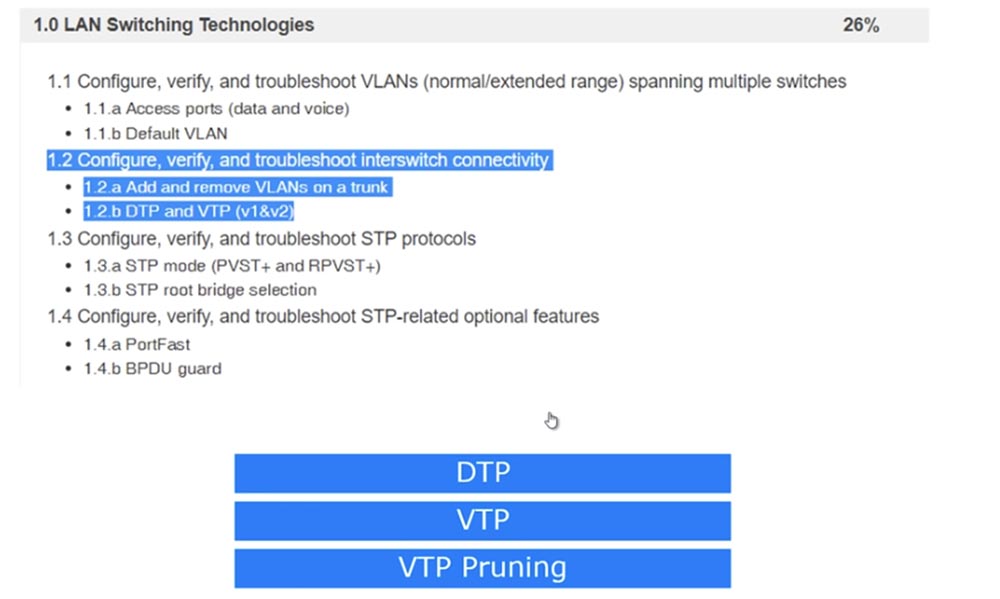
The last time we looked at item 1.1, and today we will look at 1.2 - setting up, checking, and troubleshooting network switch connections: adding and removing VLANs from a trunk and DTP and VTP protocols version 1 and 2.
All ports of the switch “out of the box” are configured by default to use the Dynamic Auto mode of the DTP protocol. This means that when two ports of different switches are connected between them, the trunk automatically turns on if one of the ports is in trunk or desirable mode. If the ports of both switches are in Dynamic Auto mode, a trunk will not form.

Thus, it all depends on the setting of the operation modes of each of the 2 switches. For ease of understanding, I have made a table of possible combinations of DTP modes of two switches. You see that if both switches use Dynamic Auto, then they do not form a trunk, but remain in Access mode. Therefore, if you want a trunk to be created between two switches, you must program at least one of the switches to Trunk mode, or program the trunk port to use Dynamic Desirable mode. As can be seen from the table, each of the switch ports can be in one of 4 modes: Access, Dynamic Auto, Dynamic Desirable, or Trunk.
If both ports are configured for Access, the connected switches will use Access mode. If one port is configured for Dynamic Auto and the other for Access, both will work in Access mode. If one port works in Access mode and the other in Trunk mode, it will not be possible to connect the switches, so this combination of modes cannot be used.
So, for trunking to work, one of the switch ports must be programmed on Trunk, and the other on Trunk, Dynamic Auto or Dynamic Desirable. A trunk is also formed if both ports are configured for Dynamic Desirable.
The difference between Dynamic Desirable and Dynamic Auto is that in the first mode, the port itself initiates the trunk by sending DTP frames to the port of the second switch. In the second mode, the port of the switch waits until someone starts talking to him, and if the ports of both switches are set to Dynamic Auto, a trunk will never form between them. In the case of Dynamic Desirable, there is a reverse situation - if both ports are configured for this mode, a trunk will necessarily form between them.
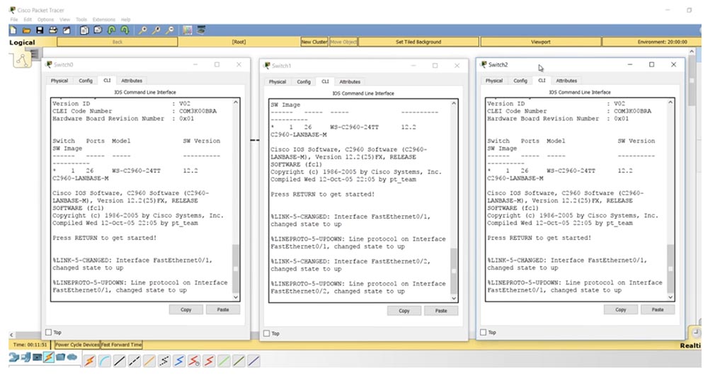
I advise you to remember this table, as it will help you properly configure switches connected to each other. Let's look at this aspect in Packet Tracer. I sequentially connected 3 switches together and now I will display the CLI console windows for each of these devices on the screen.
If I enter the show int trunk command, we will not see any trunk, which is completely natural in the absence of the necessary settings, since all switches are configured for Dynamic Auto mode. If I ask you to show the parameters of the f0 / 1 interface of the middle switch, you will see that in the administrative settings mode the dynamic auto parameter is displayed.

The third and first switches have similar settings - they also have the f0 / 1 port in dynamic auto mode. If you remember the table, for trunking, all ports must be in trunk mode or one of the ports must be in Dynamic Desirable mode.
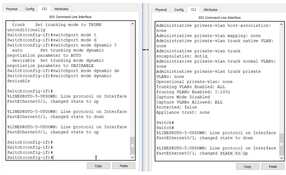
Let's go into the settings of the first switch SW0 and configure the port f0 / 1. After entering the switchport mode command, the system will give hints of possible mode parameters: access, dynamic or trunk. I use the switchport mode dynamic desirable command, while you can notice how the trunk port f0 / 1 of the second switch after entering this command first went down, and then, after receiving the DTP frame of the first switch, went up.
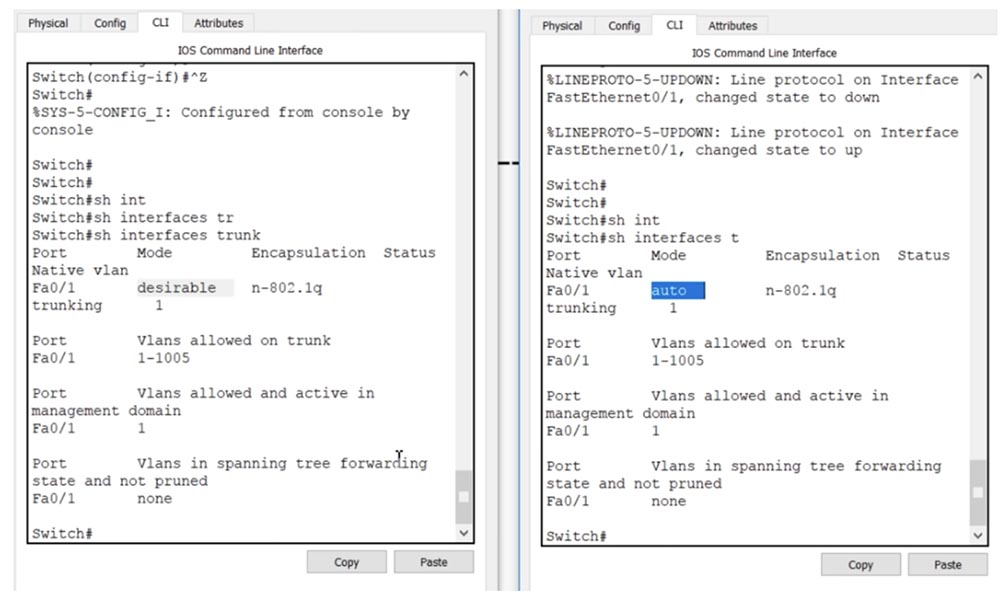
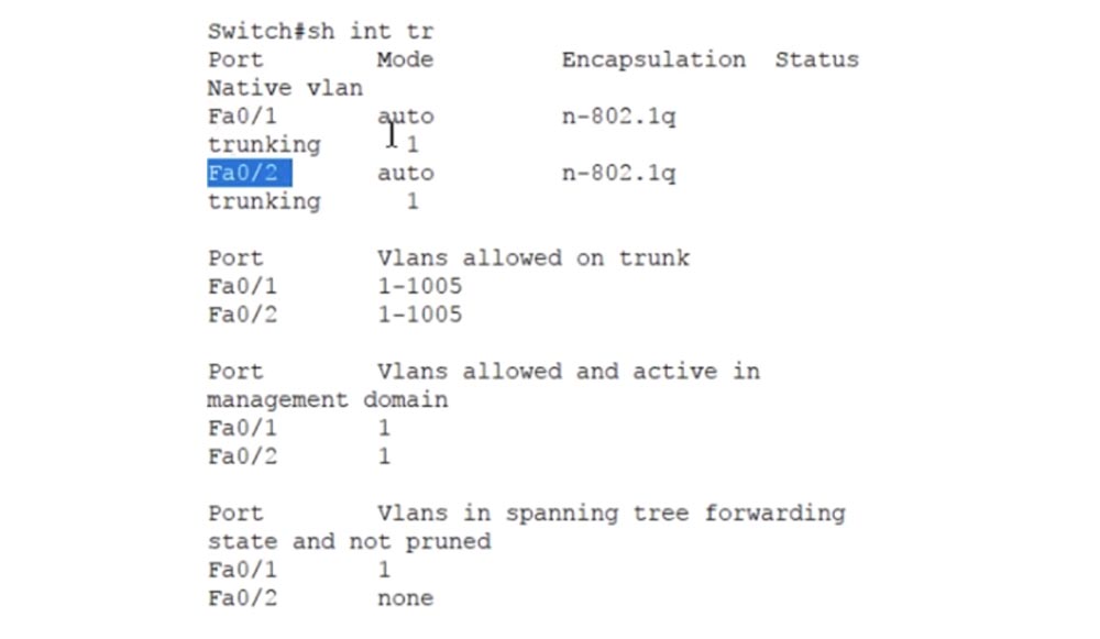
If we now enter the show int trunk command in the CLI console of switch SW1, we will see that port f0 / 1 is in a trunking state. I enter the same command in the console of the switch SW1 and see the same information, that is, now a trunk is installed between the switches SW0 and SW1. The port of the first switch is in desirable mode, and the port of the second is in auto mode.
There is no connection between the second and third switches, so I go to the settings of the third switch and enter the switchport mode dynamic desirable command. You see that in the second switch the same down-up state changes occurred, only now they touch the port f0 / 2, to which 3 switches are connected. Now the second switch has two trunks: one on the f0 / 1 interface, the second on f0 / 2. This can be seen by using the show int trunk command.
Both ports of the second switch are in auto state, that is, for trunking with neighboring switches, their ports must be in trunk or desirable mode, because in this case there are only 2 modes for installing the trunk. Using the table, you can always configure the ports of switches in such a way as to organize a trunk between them. This is the essence of using the dynamic DTP trunking protocol.
Let's get down to the VLAN trunking protocol, or VTP. This protocol provides synchronization of VLAN databases of different network devices, transferring the updated VLAN database from one device to another. Let's return to our scheme of 3 switches. VTP can work in 3 modes: server, client and transparent. VTP v3 has another mode called Off, but only the first and second versions of VTP are covered in the Cisco exam topic.

Server mode is used to create new VLANs, delete or change networks through the switch command line. In client mode, no operations can be performed on the VLAN; in this mode, only the VLAN database is updated from the server. The transparent mode acts as if the VTP protocol is disabled, that is, the switch does not issue its own VTP messages, but sends updates from other switches - if the update arrives at one of the switch’s ports, it passes it through itself and sends it further over the network through another port . In transparent mode, the switch simply serves as a transmitter of other people's messages without updating its own VLAN database.
On this slide, you see the VTP protocol configuration commands entered in global configuration mode. The first command allows you to change the protocol version used. The second command selects the VTP mode of operation.

If you want to create a VTP domain, use the vtp domain <domain name> command, and to set the VTP password, you must enter the vtp password <PASSWORD> command. Let's go to the CLI console of the first switch and look at the VTP state by issuing the show vtp status command.
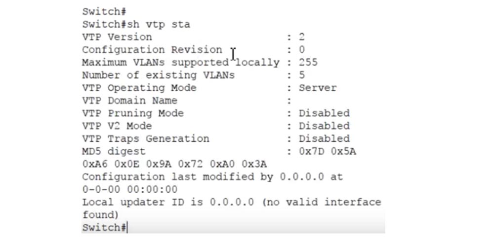
You see the version of the VTP protocol - the second, the maximum number of supported VLANs is 255, the number of existing VLANs is 5, and the VLAN mode of operation is the server. These are all default settings. We've already discussed VTP in the Day 30 lesson, so if you forget something, you can come back and review this video again.
In order to see the VLAN database, I enter the show vlan brief command. Shown here are VLAN1 and VLAN1002-1005. By default, all free switch interfaces are connected to the first network - 23 Fast Ethernet ports and 2 Gigabit Ethernet ports, the remaining 4 VLANs are not supported. The VLAN databases of the other two switches look exactly the same, except that SW1 did not have 23 but 22 Fast Ethernet ports left free for VLANs, since f0 / 1 and f0 / 2 are occupied by trunks. Let me remind you again of what was discussed in the lesson “Day 30” - the VTP protocol supports only updating VLAN databases.
If I configure several ports to work with VLANs with the switchport access and switchport mode access commands VLAN10, VLAN20 or VLAN30, the configuration of these ports will not be replicated using VTP because VTP updates only the VLAN database.
So, if one of the SW1 ports is configured to work with VLAN20, but this network is not in the VLAN database, then the port will be disabled. In turn, database updates occur only when using the VTP protocol.
Using the show vtp status command, I can see that all 3 switches are in server mode now. I will switch the middle switch SW1 to transparent mode with the vtp mode transparent command, and the third switch SW2 to client mode with the vtp mode client command.
Now let's go back to the first switch SW0 and create the nwking.org domain using the vtp domain <domain name> command. If you now look at the state of the VTP of the second switch, which is in transparent mode, you can see that it did not react at all to the creation of the domain - the VTP Domain Name field remained empty. However, the third switch, which is in client mode, has updated its database and it has the domain name VTP-nwking.org. Thus, the update of the switch database SW0 passed through SW1 and affected SW2.
Now I’ll try to change the given domain name, for which I’ll go into the settings of SW0 and type the vtp domain NetworKing command. As you can see, this time the update did not happen - the VTP domain name on the third switch remained the same. The fact is that such a domain name update occurs only 1 time when the default domain is changed. If after that the VTP domain name changes again, on the other switches it will need to be changed manually.
Now I will create a new VLAN100 network in the CLI console of the first switch and call it IMRAN. It appeared in the VLAN database of the first switch, but did not appear in the database of the third switch, because these are different domains. Remember that the VLAN database is updated only if both switches have the same domain, or, as I showed earlier, a new domain name is set instead of the default name.
I go into the settings of 3 switches and sequentially enter the vtp mode and vtp domain NetworKing commands. Please note that entering the name is case sensitive, so the spelling of the domain name must be exactly the same for both switches. Now I again put SW2 in client mode using the vtp mode client command. Let's see what happens. As you can see, now, when the domain name coincides, the SW2 database has been updated and a new VLAN100 IMRAN has appeared in it, and these changes have not affected the average switch in any way, because it is in transparent mode.
If you want to protect yourself from unauthorized access, you can create a VTP password. In this case, you must be sure that the device on the other side will have exactly the same password, because only in this case it will be able to receive VTP updates.
The next thing we will consider is VTP pruning, or “trimming” of unused VLANs. If you have 100 devices using the VTP protocol on your network, then updating the VLAN database of one device will automatically be replicated to the remaining 99 devices. However, not all of these devices have the VLANs mentioned in the update, so information about them may not be needed.
 \
\
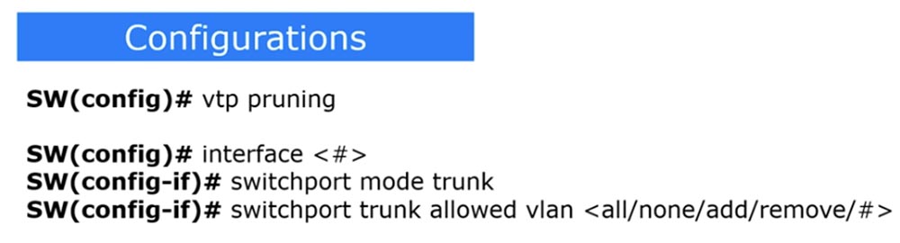
Distribution of VLAN database updates to devices using VTP means that all ports of all devices will receive information about added, deleted and changed VLANs, to which they may have nothing to do. At the same time, the network is clogged with excess traffic. To prevent this from happening, the VTP pruning concept is used. In order to enable the mode of “trimming” of irrelevant VLANs on the switch, the vtp pruning command is used. After that, the switches will automatically inform each other about which VLAN they actually use, thereby warning neighbors that they do not need to send updates to networks that are not connected to them.
For example, if SW2 does not have any VLAN10 ports, then it does not need SW1 to send it traffic for this network. At the same time, switch SW1 needs VLAN10 traffic, because one of its ports is connected to this network, it just does not need to send this traffic to switch SW2.
Therefore, if SW2 uses vtp pruning mode, it tells SW1: "please do not send me traffic for VLAN10 because this network is not connected to me and not one of my ports is configured to work with this network." Here is what using the vtp pruning command gives.
There is another way to filter traffic for a specific interface. It allows you to configure a port on a trunk with a specific VLAN. The disadvantage of this method is the need to manually configure each trunk port, which will need to indicate which VLANs are allowed and which are prohibited. For this, a sequence of 3 teams is used. The first indicates the interface that these restrictions concern, the second turns this interface into a trunk port, and the third - switchport trunk allowed vlan <all / none / add / remove / VLAN number> - shows which VLAN is allowed on this port: all, none one, added VLAN or deleted VLAN.
Depending on the specific situation, you choose what to use: VTP pruning or Trunk allowed. Some organizations prefer not to use VTP for security reasons, so they choose to manually configure trunking. Since the vtp pruning command does not work in Packet Tracer, I will show it in the GNS3 emulator.
If you go into the settings of SW2 and enter the vtp pruning command, the system will immediately inform you that this mode is turned on: Pruning switched on, that is, VLAN “trimming” is turned on with just one command.
If we type the show vtp status command, we see that vtp pruning mode is enabled.

If you configure this mode on the switch server, then go to its settings and enter the vtp pruning command. This means that devices connected to the server will automatically use vtp pruning to minimize trunking traffic for outdated VLANs.
If you do not want to use this mode, you must enter a specific interface, for example, e0 / 0, and then type the switchport trunk allowed vlan command. The system will give you tips on the possible parameters of this command:
- WORD - VLAN number that will be resolved on this interface in trunk mode;
- add - VLAN to be added to the VLAN database list;
- all - enable all VLANs;
- except - allow all VLANs except those specified;
- none - disable all VLANs;
- remove - remove VLAN from the list of VLAN database.
For example, if we have a trunk enabled for VLAN10 and want to enable it for VLAN20, then you need to enter the switchport trunk allowed vlan add 20 command.

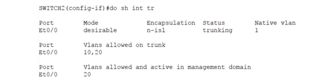
I want to show you something else, so I use the show interface trunk command. Note that by default, all VLAN 1-1005 were allowed for the trunk, and now VLAN10 has been added to them.

If I use the switchport trunk allowed vlan add 20 command and ask again to show the trunking status, we will see that now two networks are allowed for the trunk - VLAN10 and VLAN20.
At the same time, no traffic other than that intended for these networks can pass through this trunk. By allowing traffic only for VLAN 10 and VLAN 20, we have denied traffic for all other VLANs. Here's how to manually configure trunking parameters for a specific VLAN on a specific switch interface.
Please note that until the end of the day on November 17, 2017, our site has a 90% discount on the cost of downloading laboratory work on this topic.

Thank you and see you at the next video tutorial!
Thank you for staying with us. Do you like our articles? Want to see more interesting materials? Support us by placing an order or recommending it to your friends, a 30% discount for Habr users on a unique analogue of entry-level servers that was invented by us for you: The whole truth about VPS (KVM) E5-2650 v4 (6 Cores) 10GB DDR4 240GB SSD 1Gbps from $ 20 or how to divide the server? (options are available with RAID1 and RAID10, up to 24 cores and up to 40GB DDR4).
Dell R730xd 2 times cheaper? Only we have 2 x Intel TetraDeca-Core Xeon 2x E5-2697v3 2.6GHz 14C 64GB DDR4 4x960GB SSD 1Gbps 100 TV from $ 199 in the Netherlands! Dell R420 - 2x E5-2430 2.2Ghz 6C 128GB DDR3 2x960GB SSD 1Gbps 100TB - from $ 99! Read about How to Build Infrastructure Bldg. class c using Dell R730xd E5-2650 v4 servers costing 9,000 euros for a penny?
The last time we looked at item 1.1, and today we will look at 1.2 - setting up, checking, and troubleshooting network switch connections: adding and removing VLANs from a trunk and DTP and VTP protocols version 1 and 2.
All ports of the switch “out of the box” are configured by default to use the Dynamic Auto mode of the DTP protocol. This means that when two ports of different switches are connected between them, the trunk automatically turns on if one of the ports is in trunk or desirable mode. If the ports of both switches are in Dynamic Auto mode, a trunk will not form.
Thus, it all depends on the setting of the operation modes of each of the 2 switches. For ease of understanding, I have made a table of possible combinations of DTP modes of two switches. You see that if both switches use Dynamic Auto, then they do not form a trunk, but remain in Access mode. Therefore, if you want a trunk to be created between two switches, you must program at least one of the switches to Trunk mode, or program the trunk port to use Dynamic Desirable mode. As can be seen from the table, each of the switch ports can be in one of 4 modes: Access, Dynamic Auto, Dynamic Desirable, or Trunk.
If both ports are configured for Access, the connected switches will use Access mode. If one port is configured for Dynamic Auto and the other for Access, both will work in Access mode. If one port works in Access mode and the other in Trunk mode, it will not be possible to connect the switches, so this combination of modes cannot be used.
So, for trunking to work, one of the switch ports must be programmed on Trunk, and the other on Trunk, Dynamic Auto or Dynamic Desirable. A trunk is also formed if both ports are configured for Dynamic Desirable.
The difference between Dynamic Desirable and Dynamic Auto is that in the first mode, the port itself initiates the trunk by sending DTP frames to the port of the second switch. In the second mode, the port of the switch waits until someone starts talking to him, and if the ports of both switches are set to Dynamic Auto, a trunk will never form between them. In the case of Dynamic Desirable, there is a reverse situation - if both ports are configured for this mode, a trunk will necessarily form between them.
I advise you to remember this table, as it will help you properly configure switches connected to each other. Let's look at this aspect in Packet Tracer. I sequentially connected 3 switches together and now I will display the CLI console windows for each of these devices on the screen.
If I enter the show int trunk command, we will not see any trunk, which is completely natural in the absence of the necessary settings, since all switches are configured for Dynamic Auto mode. If I ask you to show the parameters of the f0 / 1 interface of the middle switch, you will see that in the administrative settings mode the dynamic auto parameter is displayed.
The third and first switches have similar settings - they also have the f0 / 1 port in dynamic auto mode. If you remember the table, for trunking, all ports must be in trunk mode or one of the ports must be in Dynamic Desirable mode.
Let's go into the settings of the first switch SW0 and configure the port f0 / 1. After entering the switchport mode command, the system will give hints of possible mode parameters: access, dynamic or trunk. I use the switchport mode dynamic desirable command, while you can notice how the trunk port f0 / 1 of the second switch after entering this command first went down, and then, after receiving the DTP frame of the first switch, went up.
If we now enter the show int trunk command in the CLI console of switch SW1, we will see that port f0 / 1 is in a trunking state. I enter the same command in the console of the switch SW1 and see the same information, that is, now a trunk is installed between the switches SW0 and SW1. The port of the first switch is in desirable mode, and the port of the second is in auto mode.
There is no connection between the second and third switches, so I go to the settings of the third switch and enter the switchport mode dynamic desirable command. You see that in the second switch the same down-up state changes occurred, only now they touch the port f0 / 2, to which 3 switches are connected. Now the second switch has two trunks: one on the f0 / 1 interface, the second on f0 / 2. This can be seen by using the show int trunk command.
Both ports of the second switch are in auto state, that is, for trunking with neighboring switches, their ports must be in trunk or desirable mode, because in this case there are only 2 modes for installing the trunk. Using the table, you can always configure the ports of switches in such a way as to organize a trunk between them. This is the essence of using the dynamic DTP trunking protocol.
Let's get down to the VLAN trunking protocol, or VTP. This protocol provides synchronization of VLAN databases of different network devices, transferring the updated VLAN database from one device to another. Let's return to our scheme of 3 switches. VTP can work in 3 modes: server, client and transparent. VTP v3 has another mode called Off, but only the first and second versions of VTP are covered in the Cisco exam topic.
Server mode is used to create new VLANs, delete or change networks through the switch command line. In client mode, no operations can be performed on the VLAN; in this mode, only the VLAN database is updated from the server. The transparent mode acts as if the VTP protocol is disabled, that is, the switch does not issue its own VTP messages, but sends updates from other switches - if the update arrives at one of the switch’s ports, it passes it through itself and sends it further over the network through another port . In transparent mode, the switch simply serves as a transmitter of other people's messages without updating its own VLAN database.
On this slide, you see the VTP protocol configuration commands entered in global configuration mode. The first command allows you to change the protocol version used. The second command selects the VTP mode of operation.
If you want to create a VTP domain, use the vtp domain <domain name> command, and to set the VTP password, you must enter the vtp password <PASSWORD> command. Let's go to the CLI console of the first switch and look at the VTP state by issuing the show vtp status command.
You see the version of the VTP protocol - the second, the maximum number of supported VLANs is 255, the number of existing VLANs is 5, and the VLAN mode of operation is the server. These are all default settings. We've already discussed VTP in the Day 30 lesson, so if you forget something, you can come back and review this video again.
In order to see the VLAN database, I enter the show vlan brief command. Shown here are VLAN1 and VLAN1002-1005. By default, all free switch interfaces are connected to the first network - 23 Fast Ethernet ports and 2 Gigabit Ethernet ports, the remaining 4 VLANs are not supported. The VLAN databases of the other two switches look exactly the same, except that SW1 did not have 23 but 22 Fast Ethernet ports left free for VLANs, since f0 / 1 and f0 / 2 are occupied by trunks. Let me remind you again of what was discussed in the lesson “Day 30” - the VTP protocol supports only updating VLAN databases.
If I configure several ports to work with VLANs with the switchport access and switchport mode access commands VLAN10, VLAN20 or VLAN30, the configuration of these ports will not be replicated using VTP because VTP updates only the VLAN database.
So, if one of the SW1 ports is configured to work with VLAN20, but this network is not in the VLAN database, then the port will be disabled. In turn, database updates occur only when using the VTP protocol.
Using the show vtp status command, I can see that all 3 switches are in server mode now. I will switch the middle switch SW1 to transparent mode with the vtp mode transparent command, and the third switch SW2 to client mode with the vtp mode client command.
Now let's go back to the first switch SW0 and create the nwking.org domain using the vtp domain <domain name> command. If you now look at the state of the VTP of the second switch, which is in transparent mode, you can see that it did not react at all to the creation of the domain - the VTP Domain Name field remained empty. However, the third switch, which is in client mode, has updated its database and it has the domain name VTP-nwking.org. Thus, the update of the switch database SW0 passed through SW1 and affected SW2.
Now I’ll try to change the given domain name, for which I’ll go into the settings of SW0 and type the vtp domain NetworKing command. As you can see, this time the update did not happen - the VTP domain name on the third switch remained the same. The fact is that such a domain name update occurs only 1 time when the default domain is changed. If after that the VTP domain name changes again, on the other switches it will need to be changed manually.
Now I will create a new VLAN100 network in the CLI console of the first switch and call it IMRAN. It appeared in the VLAN database of the first switch, but did not appear in the database of the third switch, because these are different domains. Remember that the VLAN database is updated only if both switches have the same domain, or, as I showed earlier, a new domain name is set instead of the default name.
I go into the settings of 3 switches and sequentially enter the vtp mode and vtp domain NetworKing commands. Please note that entering the name is case sensitive, so the spelling of the domain name must be exactly the same for both switches. Now I again put SW2 in client mode using the vtp mode client command. Let's see what happens. As you can see, now, when the domain name coincides, the SW2 database has been updated and a new VLAN100 IMRAN has appeared in it, and these changes have not affected the average switch in any way, because it is in transparent mode.
If you want to protect yourself from unauthorized access, you can create a VTP password. In this case, you must be sure that the device on the other side will have exactly the same password, because only in this case it will be able to receive VTP updates.
The next thing we will consider is VTP pruning, or “trimming” of unused VLANs. If you have 100 devices using the VTP protocol on your network, then updating the VLAN database of one device will automatically be replicated to the remaining 99 devices. However, not all of these devices have the VLANs mentioned in the update, so information about them may not be needed.
\
Distribution of VLAN database updates to devices using VTP means that all ports of all devices will receive information about added, deleted and changed VLANs, to which they may have nothing to do. At the same time, the network is clogged with excess traffic. To prevent this from happening, the VTP pruning concept is used. In order to enable the mode of “trimming” of irrelevant VLANs on the switch, the vtp pruning command is used. After that, the switches will automatically inform each other about which VLAN they actually use, thereby warning neighbors that they do not need to send updates to networks that are not connected to them.
For example, if SW2 does not have any VLAN10 ports, then it does not need SW1 to send it traffic for this network. At the same time, switch SW1 needs VLAN10 traffic, because one of its ports is connected to this network, it just does not need to send this traffic to switch SW2.
Therefore, if SW2 uses vtp pruning mode, it tells SW1: "please do not send me traffic for VLAN10 because this network is not connected to me and not one of my ports is configured to work with this network." Here is what using the vtp pruning command gives.
There is another way to filter traffic for a specific interface. It allows you to configure a port on a trunk with a specific VLAN. The disadvantage of this method is the need to manually configure each trunk port, which will need to indicate which VLANs are allowed and which are prohibited. For this, a sequence of 3 teams is used. The first indicates the interface that these restrictions concern, the second turns this interface into a trunk port, and the third - switchport trunk allowed vlan <all / none / add / remove / VLAN number> - shows which VLAN is allowed on this port: all, none one, added VLAN or deleted VLAN.
Depending on the specific situation, you choose what to use: VTP pruning or Trunk allowed. Some organizations prefer not to use VTP for security reasons, so they choose to manually configure trunking. Since the vtp pruning command does not work in Packet Tracer, I will show it in the GNS3 emulator.
If you go into the settings of SW2 and enter the vtp pruning command, the system will immediately inform you that this mode is turned on: Pruning switched on, that is, VLAN “trimming” is turned on with just one command.
If we type the show vtp status command, we see that vtp pruning mode is enabled.
If you configure this mode on the switch server, then go to its settings and enter the vtp pruning command. This means that devices connected to the server will automatically use vtp pruning to minimize trunking traffic for outdated VLANs.
If you do not want to use this mode, you must enter a specific interface, for example, e0 / 0, and then type the switchport trunk allowed vlan command. The system will give you tips on the possible parameters of this command:
- WORD - VLAN number that will be resolved on this interface in trunk mode;
- add - VLAN to be added to the VLAN database list;
- all - enable all VLANs;
- except - allow all VLANs except those specified;
- none - disable all VLANs;
- remove - remove VLAN from the list of VLAN database.
For example, if we have a trunk enabled for VLAN10 and want to enable it for VLAN20, then you need to enter the switchport trunk allowed vlan add 20 command.
I want to show you something else, so I use the show interface trunk command. Note that by default, all VLAN 1-1005 were allowed for the trunk, and now VLAN10 has been added to them.
If I use the switchport trunk allowed vlan add 20 command and ask again to show the trunking status, we will see that now two networks are allowed for the trunk - VLAN10 and VLAN20.
At the same time, no traffic other than that intended for these networks can pass through this trunk. By allowing traffic only for VLAN 10 and VLAN 20, we have denied traffic for all other VLANs. Here's how to manually configure trunking parameters for a specific VLAN on a specific switch interface.
Please note that until the end of the day on November 17, 2017, our site has a 90% discount on the cost of downloading laboratory work on this topic.
Thank you and see you at the next video tutorial!
Thank you for staying with us. Do you like our articles? Want to see more interesting materials? Support us by placing an order or recommending it to your friends, a 30% discount for Habr users on a unique analogue of entry-level servers that was invented by us for you: The whole truth about VPS (KVM) E5-2650 v4 (6 Cores) 10GB DDR4 240GB SSD 1Gbps from $ 20 or how to divide the server? (options are available with RAID1 and RAID10, up to 24 cores and up to 40GB DDR4).
Dell R730xd 2 times cheaper? Only we have 2 x Intel TetraDeca-Core Xeon 2x E5-2697v3 2.6GHz 14C 64GB DDR4 4x960GB SSD 1Gbps 100 TV from $ 199 in the Netherlands! Dell R420 - 2x E5-2430 2.2Ghz 6C 128GB DDR3 2x960GB SSD 1Gbps 100TB - from $ 99! Read about How to Build Infrastructure Bldg. class c using Dell R730xd E5-2650 v4 servers costing 9,000 euros for a penny?
All Articles