We create a portable platform game on the Cortex M0 + microcontroller
Introduction
(Links to the source code and the KiCAD project are provided at the end of the article.)
Although we were born in the 8-bit era, our first computer was the Amiga 500. This is a great 16-bit machine with amazing graphics and sound, making it great for gaming. Platforming has become a very popular game genre on this computer. Many of them were very colorful and had very smooth parallax scrolling. This was made possible thanks to talented programmers who ingeniously used Amiga coprocessors to increase the number of screen colors. Take a look at LionHeart for example!

Lionheart on Amiga. This static image does not convey the beauty of the graphics.
Since the 90s, electronics has changed a lot, and now there are many small microcontrollers that allow you to create amazing things.
We have always loved platform games, and today, for just a few bucks, you can buy Raspberry Zero, install Linux, and “pretty easy” write a colorful platform game.
But this task is not for us - we do not want to shoot sparrows from a cannon!
We want to use microcontrollers with limited memory, and not a powerful system on a chip with an integrated GPU! In other words, we want difficulties!
By the way, about the possibilities of the video: some people manage to squeeze out all the juices from the AVR microcontroller in their projects (for example, in the Uzebox or Craft project of the lft developer). However, to achieve this, the AVR microcontrollers force us to write in assembler, and even though some games are very good, you will encounter serious limitations that do not allow you to create a game in 16-bit style.
Therefore, we decided to use a more balanced microcontroller / board, which allows us to write code completely in C.
He's not as powerful as Arduino Due, but not as weak as Arduino Uno. Interestingly, “Due” means “two,” and “Uno” means “one.” Microsoft taught us to count correctly (1, 2, 3, 95, 98, ME, 2000, XP, Vista, 7, 8, 10), and Arduino also went this way! We will use the Arduino Zero, which is in the middle between 1 and 2!
Yeah, according to Arduino, 1 <0 <2.
In particular, we are not interested in the board itself, but in its series of processors. The Arduino Zero has an ATSAMD21 series microcontroller with Cortex M0 + (48 MHz), 256 KB of flash memory and 32 KB of RAM.
Although the 48-MHz Cortex M0 + is much faster than the old 7-MHz MC68000 in performance, the Amiga 500 had 512 KB of RAM, hardware sprites, an integrated dual playing field, Blitter (a DMA-based image block transfer engine with a built-in pixel-accurate collision recognition system) and transparency) and Copper (a raster coprocessor that allows you to perform operations with registers based on the sweep position to create many very beautiful effects). SAMD21 does not have all this hardware (with the exception of a rather simple one compared to Blitter DMA), so a lot will be rendered programmatically.
We want to achieve the following parameters:
- Resolution 160 x 128 pixels on a 1.8-inch SPI display.
- Graphics with 16 bits per pixel;
- The highest frame rate. At least 25 fps at 12 MHz SPI, or 40 fps at 24 MHz;
- double playing field with parallax scrolling;
- everything is written in C. No assembler code;
- Pixel-accurate recognition of collisions;
- screen overlay.
It seems that achieving these goals is quite difficult. It is, especially if we refuse the code on asm!
For example, with 16-bit color, a screen size of 160 × 128 pixels will require 40 KB for the screen buffer, but we only have 32 KB of RAM! And we still need parallax scrolling on a double playing field and much more, with a frequency of at least 25/40 fps!
But for us nothing is impossible, right?
We use tricks and built-in functions of ATSAMD21! As the “hardware” we take uChip , which can be bought in the Itaca Store .
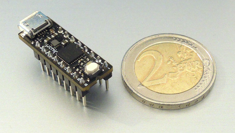
uChip: the heart of our project!
It has the same characteristics as the Arduino Zero, but much less, and is also cheaper than the original Arduino Zero (yes, you can buy a fake Arduino Zero for $ 10 on AliExpress ... but we want to build on the original). This will allow us to create a small portable console. You can almost effortlessly adapt this project for Arduino Zero, only the result will be quite cumbersome in size.
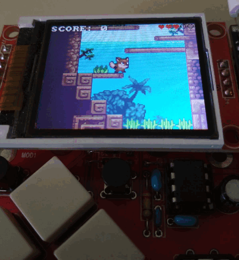
We also created a small test board that implements a portable console for the poor. Details below!

We will not use the Arduino framework. It is not well suited when it comes to optimizing and managing equipment. (And let's not talk about the IDE!)
In this article, we will describe how we came to the final version of the game, describe all the optimizations and criteria used. The game itself is not yet complete, it lacks sound, levels, etc. However, it can be used as a starting point for many different types of games!
In addition, there are many more optimization options, even without assembler!
So, let's begin our journey!
Difficulties
In fact, the project has two complex aspects: timings and memory (both RAM and storage).
Memory
Let's start with the memory. First, instead of storing a large level picture, we use tiles. In fact, if you carefully analyze most platformers, you will notice that they are created from a small number of graphic elements (tiles) that are repeated many times.
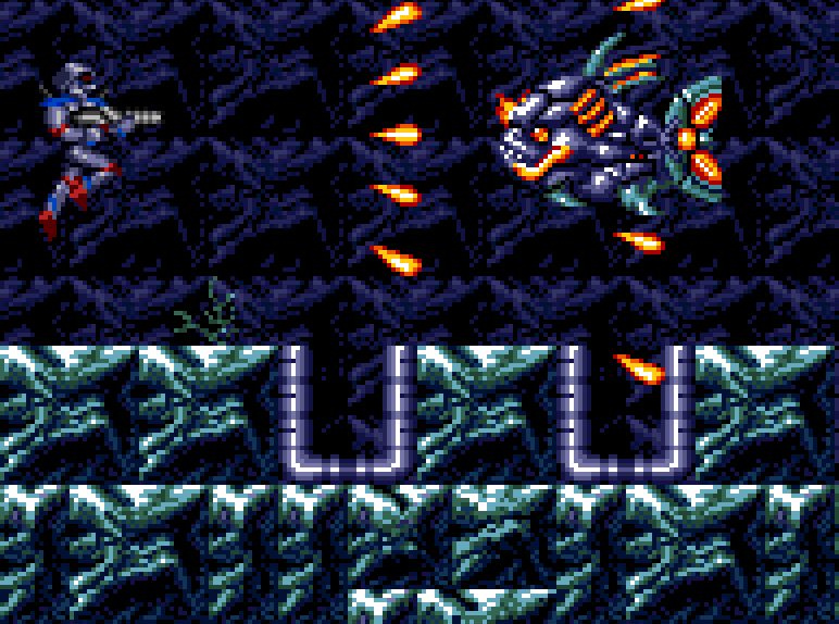
Turrican 2 on Amiga. One of the best platform games of all time. You can easily see tiles in it!
The world / level seems diverse thanks to various combinations of tiles. This saves a lot of memory on the drive, but does not solve the problem of a huge frame buffer.
The second trick we use is possible due to the rather large computational power of uC and the presence of DMA! Instead of storing all the frame data in RAM (and why is this necessary?) We will create a scene in every frame from scratch. In particular, we will continue to use buffers, but such that they fit in one horizontal block of data graphics with a height of 16 pixels.
Timings - CPU
When an engineer needs to create something, he first checks to see if this is possible. Of course, at the very beginning we performed this test!
So, we need at least 25 fps on a screen of 160 × 128 pixels. That is 512,000 pixels / s. Since the microcontroller operates at a frequency of 48 MHz, we have at least 93 clock cycles per pixel. This value drops to 58 cycles if we aim at 40 fps.
In fact, our microcontroller is capable of processing up to 2 pixels at a time, because each pixel takes 16 bits, and the ATSAMD21 has a 32-bit internal bus, that is, the performance will be even better!
A value of 93 clock cycles tells us that the task is completely doable! In fact, we can conclude that the CPU alone can handle all the rendering tasks without DMA. Most likely, this is true, especially when working with assembler. However, the code will be very difficult to handle. And in C it has to be very optimized! In fact, Cortex M0 + is not as C-friendly as Cortex M3, and it lacks a lot of instructions (it doesn’t even load / save with a subsequent / preliminary increment / decrement!), Which must be implemented with two or more simple instructions.
Let's see what we need to do to draw two playing fields (assuming we already know the x and y coordinates, etc.).
- Calculate the location of the foreground pixel in flash memory.
- Get the pixel value.
- If it is transparent, then calculate the position of the background pixel in the flash memory.
- Get the pixel value.
- Calculate the target location.
- Save pixel to buffer.
Moreover, for each sprite that can get into the buffer, the following operations should be performed:
- Calculate the position of a sprite pixel in flash memory.
- Getting the pixel value.
- If it is not transparent, then calculate the location of the destination buffer.
- Saving a pixel in the buffer.
All these operations are not only not implemented as a single ASM instruction, but each ASM instruction requires two cycles when accessing RAM / flash memory.
In addition, we still do not have gameplay logic (which, fortunately, takes a small amount of time, because it is calculated once per frame), collision recognition, buffer processing and instructions necessary for sending data via SPI.
For example, here is the pseudo-code of what we have to do (for now, we assume that the game does not have scrolling, and the playing field has a constant color background!) Only for the foreground.
Let cameraY and cameraX be the coordinates of the upper left corner of the display in the game world.
Let xTilepos and yTilepos be the position of the current tile on the map.
xTilepos = cameraX / 16; // this is a rightward shift of 4 bits. yTilepos = cameraY / 16; destBufferAddress = &buffer[0][0]; for tile = 0...9 nTile = gameMap[yTilepos][xTilepos]; tileDataAddress = &tileData[nTile]; xTilepos = xTilepos + 1; for y = 0…15 for x = 0…15 pixel = *tileDataAddress; tileDataAddress = tileDataAddress + 1; *destBufferAddress = pixel; destBufferAddress = destBufferAddress + 1; next destBufferAddress = destBufferAddress + 144; // point to next row next destBufferAddress = destBufferAddress – ( 160 * 16 - 16); // now point to the position where the next tile will be saved. next
The number of instructions for 2560 pixels (160 x 16) is approximately 16k, i.e. 6 per pixel. In fact, you can draw two pixels at a time. This halves the actual number of instructions per pixel, that is, the number of high-level instructions per pixel is approximately equal to 3. However, some of these high-level instructions will either be divided into two or more assembler instructions, or require at least two cycles to complete because they access to the memory. Also, we did not consider resetting the CPU pipeline due to jumps and wait states for flash memory. Yes, we are still far from 58-93 cycles at our disposal, but we still need to take into account the background of the playing field and sprites.
Although we can see that the problem can be solved on one CPU as well, DMA will be much faster. Direct access to the memory leaves even more opportunities for screen sprites or improved graphic effects (for example, we can implement alpha blending).
We will see that to configure the DMA for each tile, we need less than 100 C instructions, i.e. less than 0.5 per pixel! Of course, DMA will still have to perform the same number of transfers in memory, but the address increment and transmission are performed without the intervention of the CPU, which can do something else (for example, calculating and rendering sprites).
Using the SysTick timer, we found out that the time required to prepare the DMA for the whole block, and then to complete the DMA, is approximately 12k clock cycles. Note: clock cycles! Not high level instructions! The number of cycles is quite high for only 2560 pixels, i.e. 1,280 32-bit words. In fact, we get about 10 cycles per 32-bit word. However, you need to consider the time required to prepare the DMA, as well as the time it takes for the DMA to load transfer descriptors from RAM (which essentially contain pointers and the number of bytes transferred). In addition, there is always some kind of memory bus change (so that the CPU does not stand idle without data), and flash memory requires at least one wait state.
Timings - SPI
Another bottleneck is SPI. Is 12 MHz enough for 25 fps? The answer is yes: 12 MHz corresponds to about 36 frames per second. If we use 24 MHz, then the limit will double!
By the way, the specifications of the display and the microcontroller say that the maximum SPI speed is respectively 15 and 12 MHz. We tested and made sure that it can be increased without problems to 24 MHz, at least in the “direction” we need (the microcontroller writes to the display).
We will use the popular 1.8-inch SPI display. We made sure that both ILI9163 and ST7735 operate normally with a frequency of 12 MHz (at least with 12 MHz. It is verified that the ST7735 operates with a frequency of up to 24 MHz). If you want to use the same display as in the tutorial “How to play videos on Arduino Uno”, we recommend that you modify it in case you want to add SD support in the future. We are using the version with an SD card so that we have a lot of space for other elements, such as sound or additional levels.
Graphic arts
As already mentioned, the game uses tiles. Each level will consist of tiles repeating according to the table, which we called "gameMap". How big will each tile be? The size of each tile greatly affects memory consumption, detail, and flexibility (and, as we will see later, speed too). Too large tiles will require the creation of a new tile for each small variation we need. This will take up a lot of space on the drive.
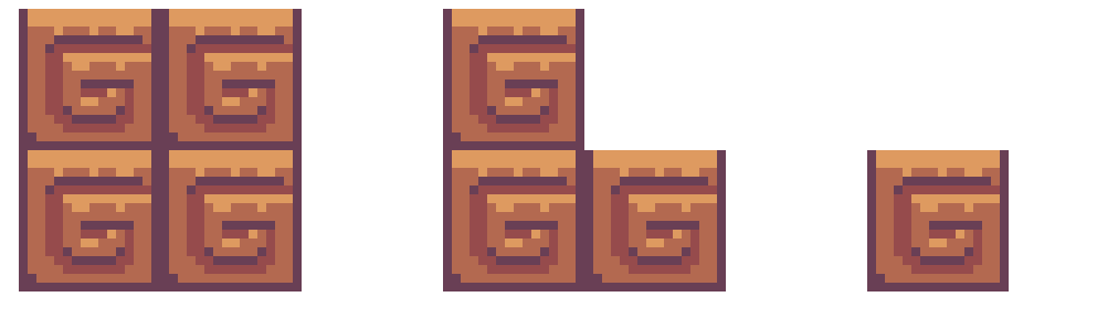
Two tiles 32 × 32 pixels in size (left and center), differing in a small part (the upper right part of the pixel is 16 × 16). Therefore, we need to store two different tiles 32 × 32 pixels in size. If we use a 16 × 16 pixel tile (on the right), then we need to store only two 16 × 16 tiles (a completely white tile and a tile on the right). However, when using 16 × 16 tiles, we get 4 map elements.
However, fewer tiles per screen are required, which increases the speed (see below) and reduces the size of the map (i.e. the number of rows and columns in the table) of each level. Too small tiles create the opposite problem. Map tables are getting bigger and speed is getting slower. Of course, we will not make stupid decisions. for example, select tiles of size 17 × 31 pixels. Our faithful friend - degrees two! The size 16 × 16 is almost the “golden rule”, it is used in many games, and we will choose it!
Our screen has a size of 160 × 128. In other words, we need 10 × 8 tiles per screen, i.e. 80 entries in the table. For a large level of 10 × 10 screens (or 100 × 1 screens), only 8,000 records will be required (16 KB if we use 16 bits for recording. Later we will show why we decided to choose 16 bits for recording).
Compare this with the amount of memory that is likely to be occupied by a large picture on the whole screen: 40 KB * 100 = 4 MB! This is madness!
Let's talk about the rendering system.
Each frame should contain (in drawing order):
- background graphics (back playing field)
- the level graph itself (foreground).
- sprites
- text / top overlay.
In particular, we will sequentially perform the following operations:
- Drawing background + foreground (tiles)
- drawing translucent tiles + sprites + top overlay
- sending data by SPI.
Background and fully opaque tiles will be drawn by DMA. A fully opaque tile is a tile in which there are no transparent pixels.

Partially transparent tile (left) and completely opaque (right). In a partially transparent tile, some pixels (in the lower left) are transparent, and therefore a background is visible through this area.
Partially transparent tiles, sprites, and overlay cannot be effectively rendered by DMA. In fact, the ATSAMD21 chip DMA system simply copies the data, and unlike the Amiga Blitter, it does not check for transparency (set by the color value). All partially transparent elements are drawn by the CPU.
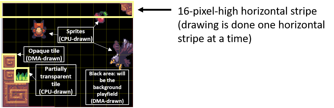
Data is then transmitted to the display using DMA.
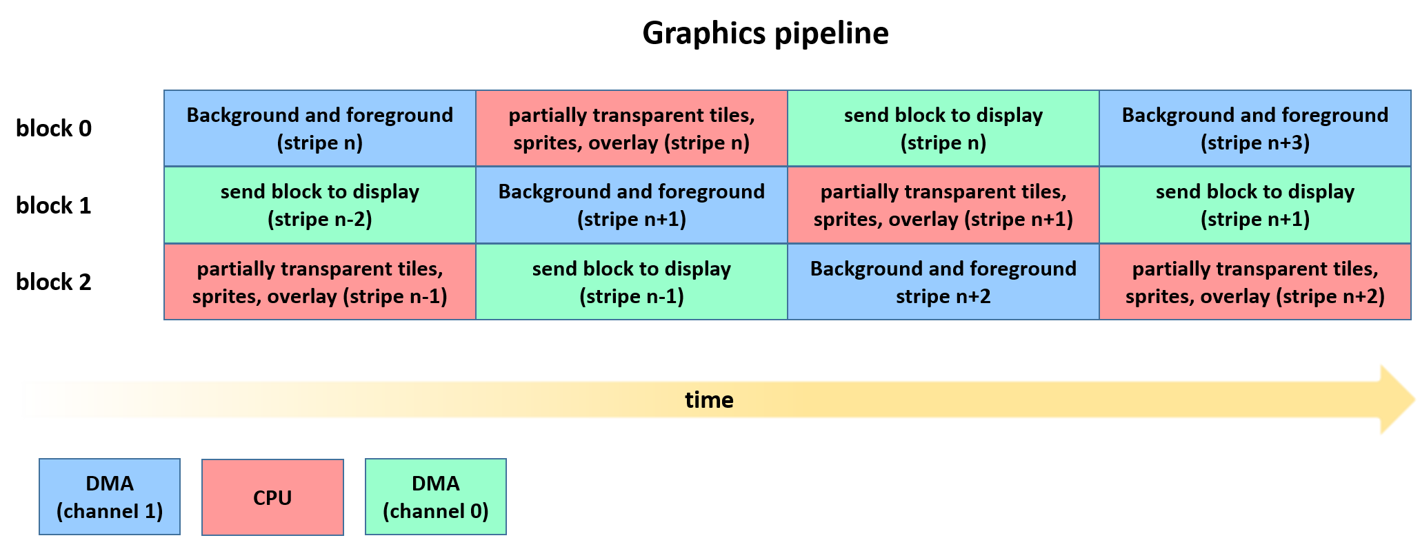
Creating a pipeline
As you can see, if we perform these operations sequentially in one buffer, it will take a lot of time. In fact, while DMA is running, the CPU will not be busy except waiting for the DMA to complete! This is a bad way to implement a graphics engine. Moreover, when DMA sends data to an SPI device, it does not use its full bandwidth. In fact, even when SPI operates at a frequency of 24 MHz, data is transmitted only at a frequency of 3 MHz, which is quite small. In other words, DMA is not used to its full potential: DMA can perform other tasks without really losing performance.
That is why we implemented the pipeline, which is the development of the idea of double buffering (we use three buffers!). Of course, in the end, operations are always performed sequentially. But the CPU and DMA simultaneously perform different tasks, without (especially) affecting each other.
Here's what happens at the same time:
- The buffer is used to draw background data using the DMA 1 channel;
- In another buffer (which was previously filled with background data), the CPU draws sprites and partially transparent tiles;
- Then another buffer (which contains a full horizontal data block) is used to send data to the display via SPI using the DMA channel 0. Of course, the buffer used to send data via SPI was previously filled with sprites while the SPI sent the previous block and while another buffer filled with tiles.
DMA
The ATSAMD21 chip DMA system is not comparable to Blitter, but nevertheless it has its own useful features. Thanks to DMA, we can provide a very high refresh rate, despite having a dual playing field.
The configuration of the DMA transmission is stored in RAM, in “DMA descriptors”, telling the DMA how and where it should perform the current transmission. These descriptors can be joined together: if there is a connection (i.e. there is no null pointer), then after the transfer is completed, the DMA will automatically receive the next descriptor. Through the use of multiple descriptors, DMA can perform “complex transfers”, which are useful when, for example, the source buffer is a sequence of non-contiguous segments of contiguous bytes. However, it takes time to get and write descriptors, because you need to save / load 16 bytes of descriptor from RAM.
DMA can work with data of different lengths: bytes, halfwords (16 bits) and words (32 bits). In the specification, this length is called the “beat size". For SPI, we are forced to use byte transfer (although the current REVD specification states that the ATSAMD21 SERCOM chips have FIFO, which, according to Microchip, can also receive 32-bit data, in fact it seems that they do not have FIFO. The REVD specification also mentions SERCOM CTRLC register, which is absent both in header files and in the register description section. Fortunately, unlike AVR, ATSAMD21 at least has a buffered transfer data register, so there will be no pauses in transmission!). To draw tiles, we, of course, use 32 bits. This allows you to copy two pixels per beat. The ATSAMD21 DMA chip also allows each source beat to increase the source or destination address by a fixed number of beat sizes.
These two aspects are very important and they determine the way we draw tiles.
Firstly, if we rendered one pixel per beat (16 bits), we would halve the throughput of our system. We cannot refuse full bandwidth!
However, if we draw two pixels per beat, the playing field will be able to scroll only an even number of pixels, due to which the smoothness of movement will suffer. To handle this, you can use a buffer that is two or more pixels larger. When sending data to the display, we will use the correct offset (0 or 1 pixel), depending on whether we need to move the “camera” by an even or odd number of pixels.
However, for the sake of simplicity, we reserve space for 11 full tiles (160 + 16 pixels), and not for 160 + 2 pixels. This approach has one big advantage: we don’t have to calculate and update the recipient address of each DMA descriptor (this would require several instructions, which could result in too many calculations per tile). Of course, we will draw only the minimum number of pixels, that is, no more than 162. Yes, in the end, we will spend a little extra memory (taking into account three buffers, this is about 1500 bytes) for speed and simplicity. You can also perform further optimizations.

All 16-line block buffers (without descriptors) are visible in this GIF animation. The right side shows what is actually displayed. The first 32 frames are shown in GIF, on which we move to the right by 1 pixel in each frame. The black area of the buffer is the part that is not updated, and its contents simply remain from previous operations. When the screen scrolls an odd number of frames, an area 162 pixels wide is drawn into the buffer. However, the first and last column of them (which are highlighted in the animation) are discarded. When the scroll value is a multiple of 16 pixels, the draw operations in the buffer start from the first column (x = 0).
What about vertical scrolling?
We will deal with it after we show a way to store tiles in flash memory.
How to store tiles
A naive approach (which would suit us if we were only rendering through the CPU) would be to store the tiles in flash memory as a sequence of pixel colors. The first pixel of the first row, the second, and so on, until the sixteenth. Then we save the first pixel of the second row, the second, and so on.
Why is such a decision naive? Because in this case, DMA can only render 16 pixels per DMA descriptor! Therefore, we need 16 descriptors, each of which needs 4 + 4 memory access operations (that is, to transfer 32 bytes - 8 memory read operations + 8 memory write operations - DMA must perform another 4 reads + 4 writes). This is pretty inefficient!
In fact, for each descriptor, DMA can only increment the source and destination addresses by a fixed number of words. After copying the first line of the tile to the buffer, the recipient address should not be increased by 1 word, but by such a value that it points to the next line of the buffer. This is not possible because each transmission descriptor indicates only the beat transmission increment, which cannot be changed.
It will be much smarter to send the first two pixels of each line of the tile sequentially, that is, pixels 0 and 1 of line 0, pixels 0 and 1 of line 1, etc., up to pixels 0 and 1 of line 15. Then we send pixels 2 and 3 of the line 0, and so on.
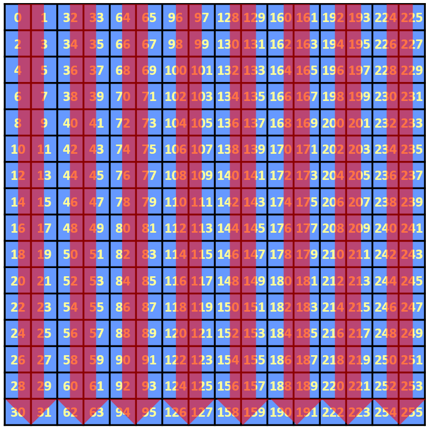
How is a tile stored?
In the figure above, each number denotes the order in which the 16-bit pixel is stored in the tile array.
This can be done with a descriptor, but we need two things:
- Tiles should be stored so that when incrementing the source by one word, we always point to the correct pixel positions. In other words, if (r, c) is a pixel in row r and column c, then we need to save pixels (0,0) (0,1) (1,0) (1,1) (2,0) sequentially (2.1) ... (15.0) (15.1) (0.2) (0.3) (1.2) (1.3) ...
- The buffer should be 256 pixels wide (not 160)
The first goal is very easy to achieve: just change the order of the data, you can do this when exporting graphics to a file c (see image above).
The second problem can be solved because DMA allows you to increase the recipient address after each beat by 512 bytes. This has two consequences:
- We cannot send data using a single descriptor over an SPI block. This is not a very serious problem, because in the end we read one descriptor through 160 pixels. Performance impact will be minimal.
- The block should have a size of 256 * 2 * 16 bytes = 8 KB, and there will be a lot of "unused space" in it.
However, this space can still be used, for example, for descriptors.
In fact, each descriptor is 16 bytes in size. We need at least 10 * 8 (and actually 11 * 8!) Descriptors for tiles and 16 descriptors for SPI.
That's why the more tiles, the higher the speed. In fact, if we used, for example, a 32 x 32 tile, then we would need fewer descriptors per screen (320 instead of 640). This would reduce the waste of resources.
Display data block
The block buffer, descriptors, and other data are stored in a structure type, which we called displayBlock_t.
displayBlock is an array of 16 displayLineData_t elements. DisplayLine data contains 176 pixels plus 80 words. In these 80 words, we store display descriptors or other useful display data (using union).
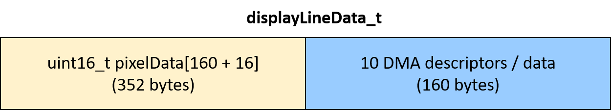
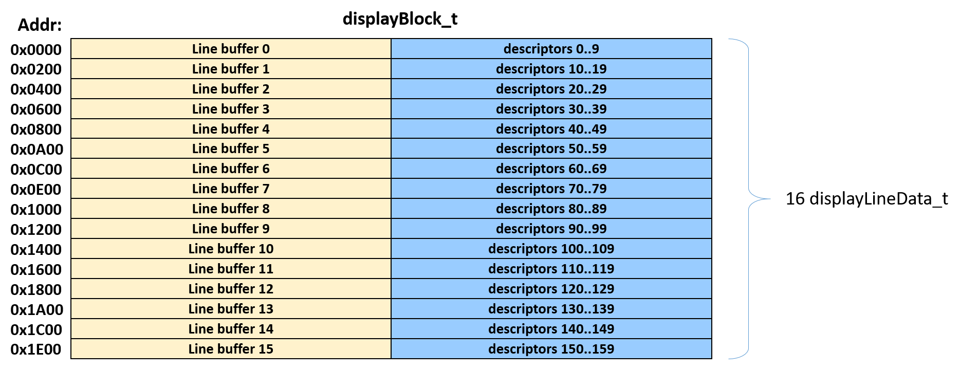
Since we have 16 lines, each tile at position X uses the first 8 DMA descriptors (0 to 7) of the X lines. Since we have a maximum of 11 tiles (the display line is 176 pixels wide), the tiles use only the first DMA descriptors 11 rows of data. Descriptors 8-9 of all lines and descriptors 0-9 of lines 11-15 are free.
Of these, descriptors 8 and 9 of line 0..7 will be used for SPI.
Descriptors 0..9 lines 11-15 (up to 50 descriptors, although we will use only 48 of them) will be used for the background playing field.
The figure below shows their structure.

Background playing field
The background playing field is handled differently. Firstly, if we need smooth scrolling, then we will have to return to the two-pixel format, because the foreground and background will scroll at different speeds. Therefore, beat will be halfway through. Despite the fact that this is a disadvantage in terms of speed, this approach facilitates integration. We only have a small number of descriptors left, so small tiles cannot be used. In addition, to simplify the work and quickly add parallax, we will use long “sectors”.
The background is drawn only if there is at least one partially transparent pixel. This means that if there is only one transparent tile, then the background will be drawn. Of course, this is an extra waste of bandwidth, but it simplifies everything.
Compare the background and front playing fields:
- In the background, sectors are used, which are long tiles stored in a "naive" way.
- The background has its own map, but horizontally it repeats. Thanks to this, less memory is used.
- Background has parallax for each sector.
Front playing field
As it was said, in each block we have up to 11 tiles (10 full tiles, or 9 full tiles and 2 partial files). Each of these tiles, if it is not marked as transparent, DMA is drawn. If it is not completely opaque, then it is added to the list, which will be analyzed later, when rendering sprites.
We connect together two playing fields
The descriptors of the background playing field (which are always calculated) and the front playing field form a very long linked list. The first part draws a background playing field. The second part draws tiles over the background. The length of the second part may be variable, because the DMA descriptors of partially transparent tiles are excluded from the list. If the block contains only opaque tiles, then DMA is configured as follows. to start directly from the first descriptor of the first tile.
Sprites and tiles with transparency
Tiles with transparency and sprites are processed almost the same. Tile / sprite pixel analysis is performed.If it is black, then it is transparent, and therefore the background tile does not change. If it is not black, then the background pixel is replaced by a sprite / tile pixel.
Vertical scrolling
When working with horizontal scrolling, we draw up to 11 tiles, even if when drawing 11 tiles, the first and last are drawn only partially. Such partial rendering is possible due to the fact that each descriptor draws two columns of the tile, so we can easily set the beginning and end of the linked list.
When working with vertical scrolling, we need to calculate both the receiver register and the transmission volume. They must be set several times per frame. To avoid this fuss, we can simply draw up to 9 full blocks per frame (8 if scrolling is a multiple of 16).
Equipment
As we said, the heart of the system is uChip. What about the rest?
Here is a diagram! Some aspects of it are worth mentioning.
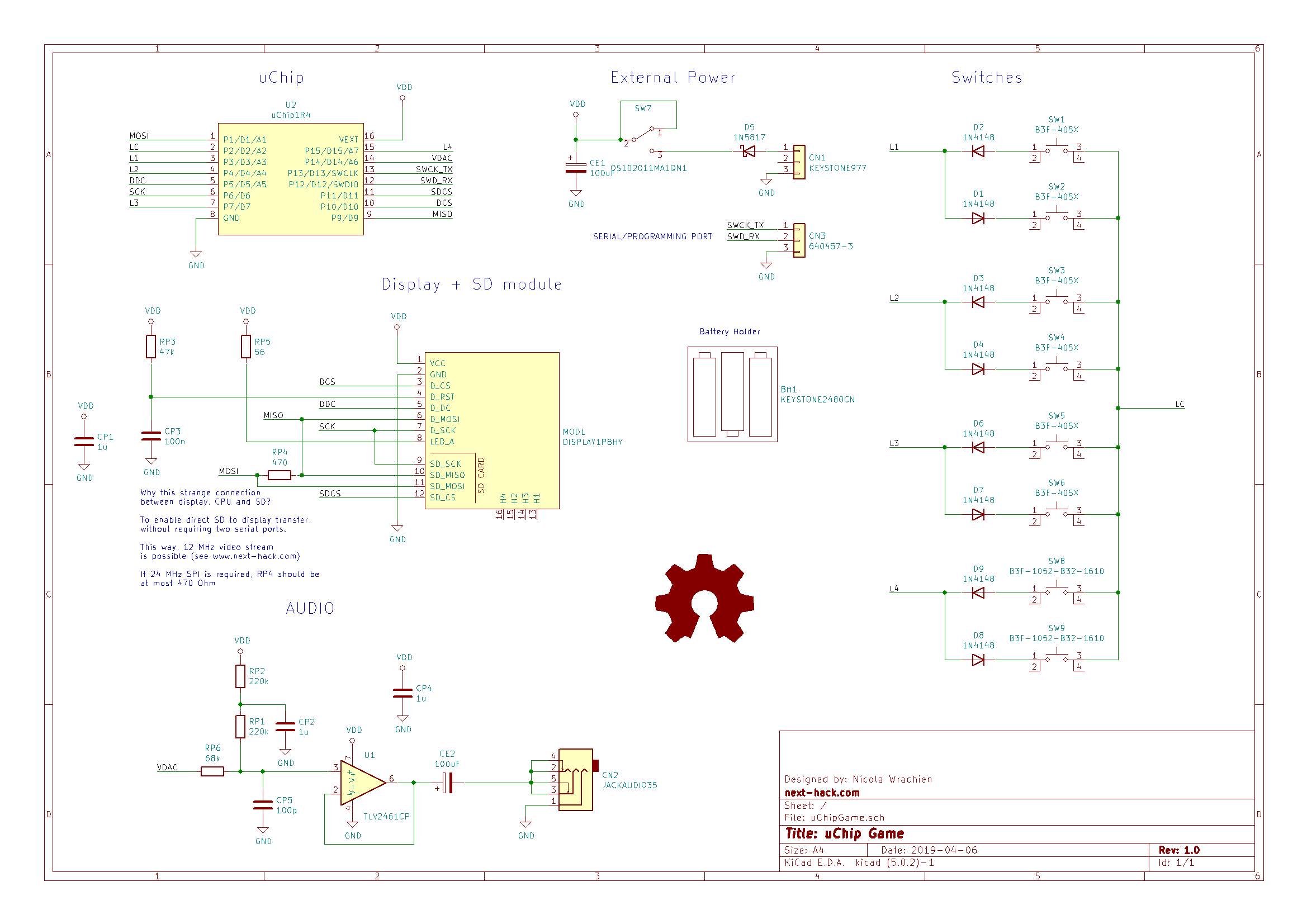
Keys
To optimize the use of I / O, we use a little trick. We will have 4 sensor buses L1-L4, and one common LC wire. 1 and 0 are alternately applied to the common wire. Accordingly, the sensor buses will alternately be pulled down or up with the help of internal pull-up resistors. Two keys are connected between each of the key buses and a common bus. A diode is inserted in series with these two keys. Each of these diodes is switched in the opposite direction, so that each time only one key is "read".
Since there is no built-in keyboard controller (and no built-in keyboard controller uses this interesting method), eight keys are quickly polled at the beginning of each frame. Since the inputs must be pulled up and down, we cannot (and do not want to) use external resistors, so we need to use integrated ones, which can have a fairly high resistance (60 kOhm). This means that when the common bus changes state, and the data buses change their pull-up / down status, you need to insert some delay so that the built-in pull-up / down resistor changes the contract and sets the stray capacitance to the desired level. But we do not want to wait! Therefore, we put the common bus in a high impedance state (so that there is no disagreement), and first change the sensor buses to logical values 1 or 0,temporarily configuring them as output. Later they are configured as input by pulling up or down. Since the output resistance is on the order of tens of Ohms, the state changes in a few nanoseconds, that is, when the sensor bus switches back to the input, it will already be in the desired state. After that, the common bus switches to the output with the opposite polarity.
This greatly improves scan speed and eliminates the need for nop delays / instructions.
SPI connection
We connected the SD and the display so that they communicate with each other without transferring data to the ATSAMD21. This can be useful if you want to play the video.
Resistors connecting MISO and MOSI should be low. If they are too large, then the SPI will not work, because the signal will be too weak.
Optimization and further development
One of the biggest problems is the use of RAM. Three blocks occupy 8 KB each, leaving only 8 KB per stack and other variables. At the moment, we have only 1.3 KB of free RAM + 4 KB of stack (4 KB per stack - this is a lot, maybe we will reduce it).
However, you can use blocks with a height of not 16, but 8 pixels. This will increase the waste of resources on DMA descriptors, but will almost halve the amount of memory occupied by the block buffer (note that the number of descriptors will not change if we continue to use 16 × 16 tiles, so we will have to change the structure of the block). This can free up approximately 7.5 KB of RAM, which will be very useful for implementing functions such as a modifiable card with secrets or adding sound (although sound can be added even with 1 KB of RAM).
Another problem is the sprite, but this modification is much simpler to perform, and you only need the createNextFrameScene () function for it. In fact, we are creating in RAM a huge array with the state of all sprites. Then, for each sprite, we calculate whether its position is within the area of the screen, and then animate it and add it to the rendering list.
Instead, you can perform optimization. For example, in gameMap you can store not only the value of the tile, but also a flag indicating the transparency of the tile, set in the editor. This will allow us to quickly check whether the tile should be rendered: DMA or CPU. That's why we used 16-bit records for the tile card. If we assume that we have a set of 256 tiles (at the moment we have less than 128 tiles, but there is enough space on the flash memory to add new ones), then there are 7 free bits that can be used for other purposes. Three of these seven bits can be used to indicate whether any sprite / object is being stored. For example:
0b000 =
0b001 =
0b010 =
0b011 =
0b100 =
0b101 =
0b110 =
0b111 = , , .
Then you can create a bit table in RAM in which each bit means whether (for example, an enemy) is detected / whether (for example, a bonus) is picked up / whether a certain object is activated (switch). At a level of 10 × 10 screens, this will require 8000 bits, i.e. 1 KB of RAM. The bit is reset when an enemy is detected or a bonus is picked up.
In createNextFrameScene (), we must check the bits corresponding to the tiles in the current visible area. If they have a value of 1:
- If this is a bonus, then just add it to the list of sprites for rendering.
- If this is the enemy, then create a dynamic sprite and reset the flag. In the next frame, the scene will contain a dynamic sprite until the enemy leaves the screen or is killed.
This approach has disadvantages.
- -, ( ). .
- -, 80 , , . , 32 . , «/» ( «», .. 0!). «», «» ( ).
- -, . ( ), . , .
- -, , , , . , , . , , , , !
- , (, Unreal Tournament , ).
Nevertheless, in this way we can store and process sprites at a level much more efficiently.
However, this technique is more relevant to the "game logic" than to the graphics engine of the game.
Perhaps in the future we will implement this function.
To summarize
We hope you enjoyed this introductory article. We need to explain many more aspects that will be the topics of future articles.
In the meantime, you can download the full source code of the game! If you like it, then you can support financially the artist ansimuz , who drew all the graphics and gave it to the world for free. We also accept donations .
The game is not finished yet. We want to add sound, many levels, objects with which you can interact and the like. You can create your own modifications! We hope to see new games with new graphics and levels!
Soon we will release a map editor, but for now it is too rudimentary to show it to the community!
Video
(Note: due to poor lighting, the video was recorded at a much lower frame rate! Soon we will update the video so that you can estimate the full speed at 40 fps!)
Thanks
The graphics of the game (and the tiles shown on some images) are taken from the free asset “Sunny Land” created by ansimuz .
Downloadable materials
The source code of the project is in the public domain, that is, it is provided free of charge. We share it in the hope that it will be useful to someone. We do not guarantee that due to any bug / error in the code there will be no problems!
Schematic diagram
KiCad
project Atmel Studio 7 project (source)
All Articles