Training Cisco 200-125 CCNA v3.0. Day 25. In-depth study of IPv6
Today we will continue to study IPv6. This lesson is quite lengthy, so we won’t waste time and start studying 3 topics: IPv6 auto-configuration, IPv6 configuration and problems, and the basics of IPv6 routing. We will devote the last topic to static routing and routing of the new generation of RIPng.
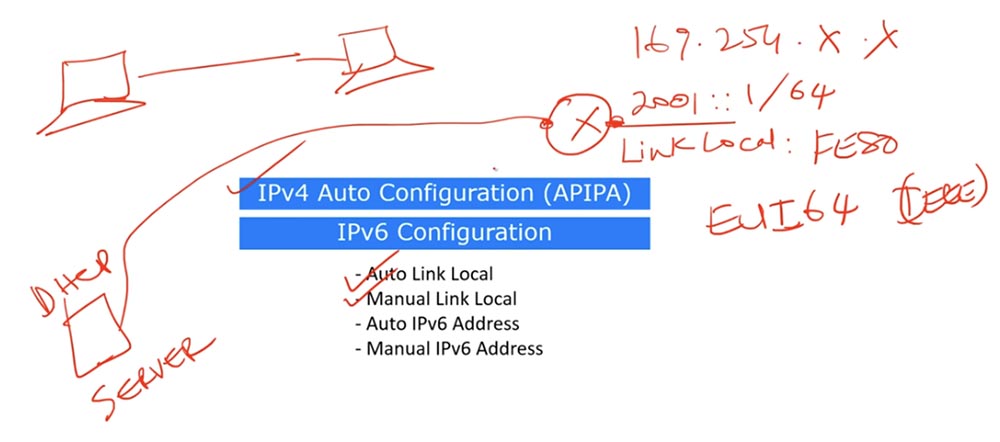
As we learned from the previous lesson, IPv4 uses the automatic configuration of internal or private IP addresses (APIPA).

This mechanism is activated when a network client tries to contact a DHCP server to obtain an IP address, but for some reason cannot do this. In this case, the IPv4 device itself assigns itself a random IP address of the form 169.254.X.X. After that, it reports its APIPA address using broadcast broadcasting, and if no other device on the network has such an IP address, it keeps it for itself. Otherwise, the client generates a new address, randomly selecting the contents of the third and fourth octets, and again uses broadcast transmission.
To make it clear what I mean, let's move on to Packet Tracer. Take a computer, go into the IPv4 network settings and set the “Static” checkbox in the “IP Configuration” item. After that, the computer will try to obtain a DHCP address, but as we can see, the device is not connected anywhere and there cannot be any DHCP server that can assign an address to it. The computer, having not received any address, must assign it to itself. However, on the command line we see only the MAC address of the device, probably because I still need to connect the computer to the switch in order to create some kind of network. I add a switch to the circuit and connect it with a cable to our computer.
In the “IP Configuration” item of network settings, the DHCP checkbox is now checked, and technically the computer itself should try to assign an IP address. In the command window, you see that this is exactly what happened - the computer assigned itself an automatically configured random address 169.254.26.192, after which its interface marker changed color from red to green, that is, a connection was established between it and the switch.
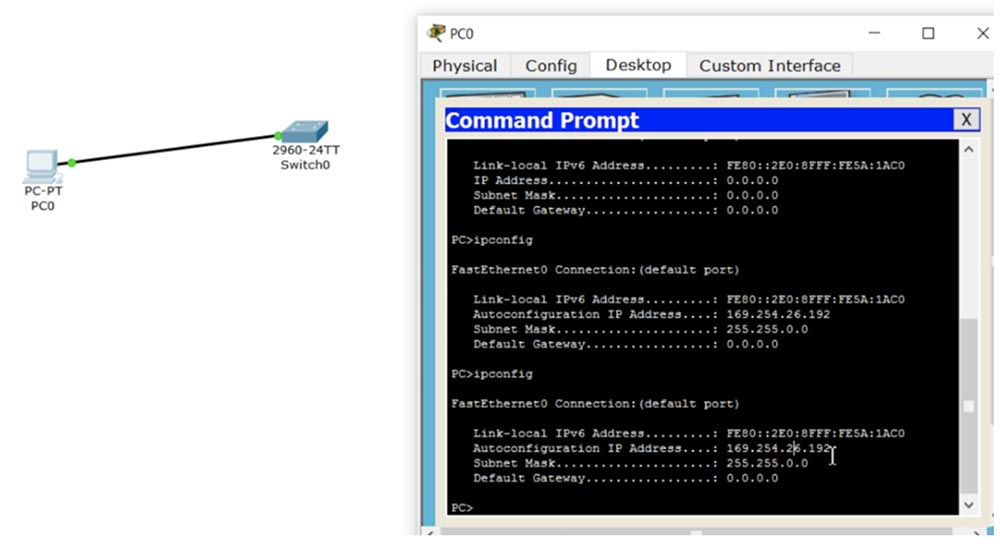
So, the computer tried to access the DHCP server through the switch, did not receive a response, because the switch is not connected to any server, and started the IP address auto-configuration mechanism. This mechanism is activated in any local area network that is not connected to the DHCP server. For example, if you have 5 computers and a switch in the local network, as a result of auto-configuration, each of them will receive its own IP address, which allows you to communicate with each other on the local network.
Let's add another computer to our network, connect it to the switch, specify DHCP in the “IP Configuration” section of the network settings and through the command line execute the command PC> ipconfig. As you can see, the second computer assigned itself the address 169.254.167.182, which is in the range of valid APIPA addresses. Now both computers have IP addresses on the same local network, and the subnet mask 255.255.0.0 points to / 16, that is, both computers can communicate with each other without problems. If I ping PC0 at 169.254.26.192, we will see that both devices can communicate over the network.
Although today we are considering IPv6 rather than IPv4, this example is convenient for understanding the principle of autoconfiguration. It shows that in a local area network with automatically configured addresses, you can freely share files from the shared folders of different computers without the need for manual configuration of IP addresses.
We looked at IPv4 address autoconfiguration, but IPv6 also has autoconfiguration. However, the autoconfiguration mechanisms of two different versions of the IP protocol are significantly different from each other. Consider the situation using IPv4 - if we take the port of the router and assign it some IP address, and then we want to change it, the new IP address will simply wipe the old one without any trace. This is the difference between IPv4 and IPv6 - in the case of IPv6, the same interface can have multiple IP addresses. In IPv4, it is possible to assign a secondary IP address to an interface using the secondary command, however, in practice, only the primary address is used in all cases. In IPv6 there is no need to assign a secondary address, you will learn about this from the following slides, which will show the configuration of such an IP address. I’ll say that if you assign two IP addresses to one interface, both of them will take part in routing and the router will have access to both addresses.
When you assign an IP address to a router or any device running IPv6, for example, 2001 :: 1/64, a Link Local address is automatically created. As mentioned in the previous lesson, Link Local address is automatically generated by the device, assigned to the interface and starts with FE80. This means that this address is assigned only to this specific interface and cannot communicate with external networks, since it works only in this segment of the local network. At the same time, the unique 48-bit MAC address of the device is used as the basis of the IP address, divided in the middle into 2 parts by the FF: FE characters. This mechanism is known as generating IP addresses using EUI-64, which is an IEEE standard. EUI-64 adds another 16 bits to the MAC address unique to each device, turning it into a unique 64-bit IP address. This is the automatic configuration of the Link Local address over IPv6.
Back to Packet Tracer, where we configured computers using IPv4, and look at the IP configuration of PC0.
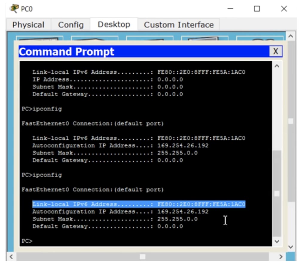
As you can see, there is both a Link Local IP address and an automatically configured IP address. However, the FE80 is part of the LAN address, and the remaining 4 octets of the IPv6 address are part of the host address. You see that just in the middle of this part of the host, FF: FE is present, creating a unique address FE80 :: 2EO: 8FFF: FE5A: 1AC0. Looking at this entry, you can determine that the unique MAC address for this device is 02EO: 8F: 5A: 1AC0. This address was automatically configured in EUI-64 format, which is a translation of the MAC address into a 64-bit IP address. The question is, can I create a Link Local address manually? Of course you can, and now we will try to do it.
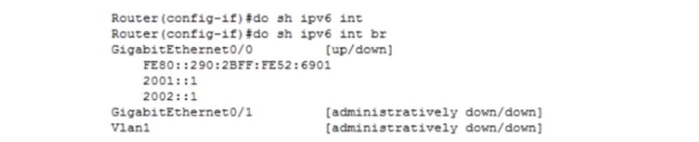
Add a Cisco router to our scheme and assign it an IP address. To do this, I enter the global settings and type in ipv6 address, not just ip address, as is done for IPv4, and then type in the address 2001 :: 1/64.

As you can see, we can dial / 64, which is very convenient! In IPv4, we could also enter a slash, but the system did not pay attention to it. Next, I enter the no shutdown command and my favorite show ip interface brief, only for interface version 6 of the protocol I definitely indicate this in the form of not just ip, but ipv6. The difference is that for the sixth version of the IP protocol in all commands instead of ip you need to use ipv6. So, I enter the do show ipv6 interface brief command, and the system shows me the IPv6 interfaces.

You see both the address assigned by us 2001 :: 1/64, and the Local Link address located above, which was automatically generated by the system. In the middle of this address, you see FF: FE, which indicate formatting the address using EUI-64.
Let's go back to the g0 / 0 interface and add another address. As I said, if I enter a new interface address in the case of IPv4, it will simply rewrite the old address. In the case of IPv6, if I enter the new address 2002 :: 1/64 and then ask me to show me the interface parameters using the do show ipv6 interface command, we will see that both addresses are available to us - both old and new.
Suppose we want to change the Link Local address. To do this, I type the ipv6 address FE80 :: 1 command. Remember that you cannot use a slash in Link Local addresses, so I add the expression link-local to the command and enter the command to change the IP address of the local network FE80 :: 1 link-local. Then I ask the system to show the new interface parameters.
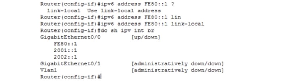
As you can see, the old Link Local address has been replaced with the new address, because the interface can have only one address like FE80 ::.
So we’ve looked at how Link Local addresses are automatically and manually assigned, and now we’ll find out what an automatic IPv6 address means.
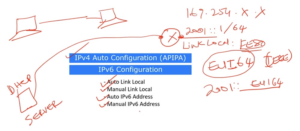
Full IPv6 auto-configuration means we have a DHCP server. Just as with IPv4, in IPv6, this server simply assigns the IP address to the device that requests it.
This configuration is used when you do not want to manually assign an IP address to the interface and the DHCP server does this automatically. If you do not have a DHCP server and you do not want to enter the address manually, but want it to be generated automatically, you can turn to EUI-64 again. This means that everything that does not start with FE80 can be an IP address, you can freely use the address of the format 2001 :: _ EUI-64_, and this is a way to automatically configure the IP address. If we use IPv6 with the / 64 slash, this means that we are manually configuring the IP address.
Now I want to show you how the automatic configuration in the EUI-64 format occurs when entering the address we selected. To do this, I will go into the CLI settings of the router and configure the IP address of the sixth version. This is done in the same way as manually configuring an IP address.
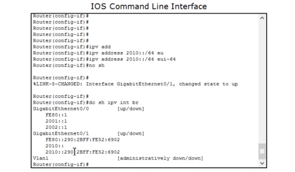
To do this, I will type ipv address 2010 :: / 64 eui-64 and no shutdown sequentially, and I can not type ipv6 completely, because the letter v after ip is perceived by the system as indicating the 6th version.
Then I will ask you to show the interface parameters, and you see that the system generated the address 2010 :: 290: 2BFF: FE52: 6902, and part of the host address in this unicast address completely repeats the MAC address of the device used as part of the host address in Local Link Address FE80 :: 290: 2BFF: FE52: 6902.
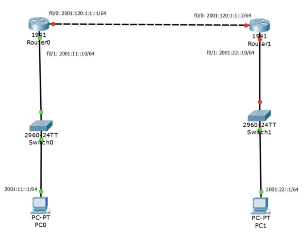
Now let's look at how IPv6 is configured. The diagram shows 2 host computers, two switches and two routers, and now I will quickly configure them.
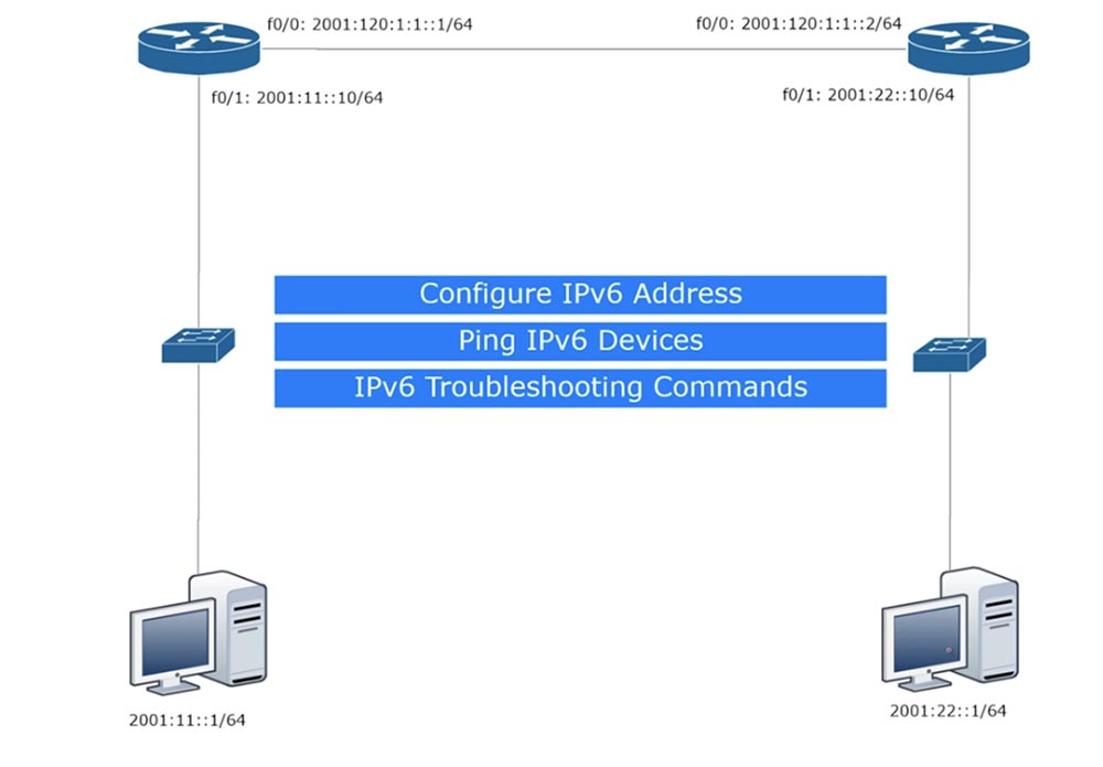
Let's move on to Packer Tracer and consider three aspects: IPv6 configuration - addresses, pinging of IPv6 devices and commands that are used to detect IPv6 problems.
On the network topology, I have already marked the IP addresses that need to be assigned to routers. I go into the PC0 network settings, disable the ability to use DHCP over IPv6 and manually configure a static IPv6 address.
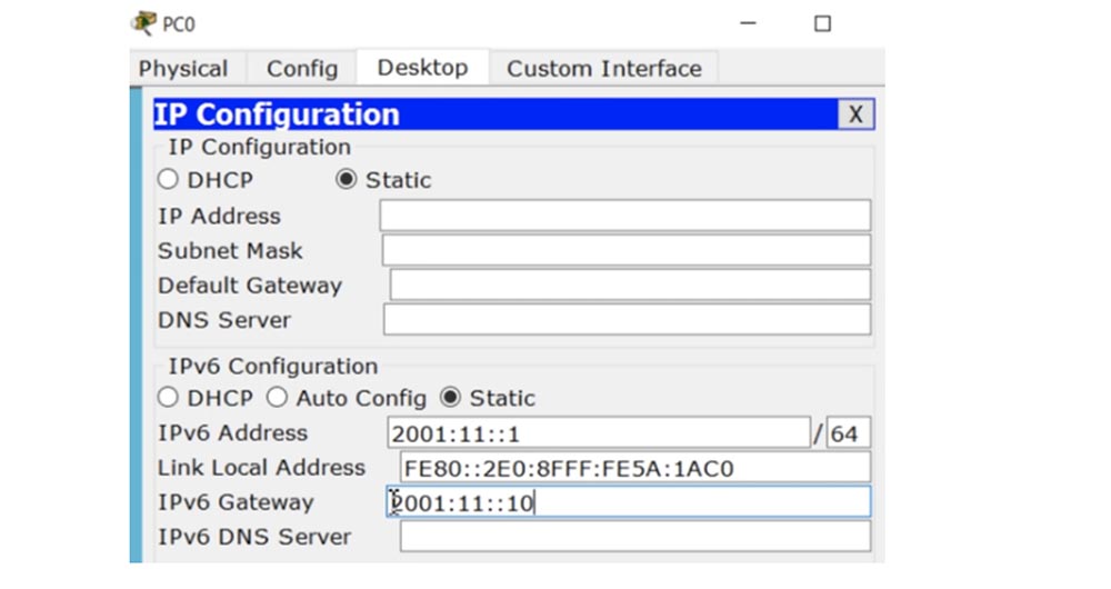
To do this, I will dial the device address 2001 :: 11 :: 1/64 and the IPv6 address of the gateway, which is Router0. The slash is not used in this address, because we know exactly where the router is located.
Similarly, PC1 is configured. This is the usual network setup in Windows, so let's not focus on it.

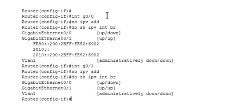
Now let's move on to the more important part of the settings. To do this, I will delete the existing IP addresses of the R0 router using the ipv add command and look at the result using the do show ip interface brief command. As you can see, the operation was successful for the g0 / 0 interface, and now I will do the same for the g0 / 1 interface. As you can see, all previously assigned IP addresses are deleted.
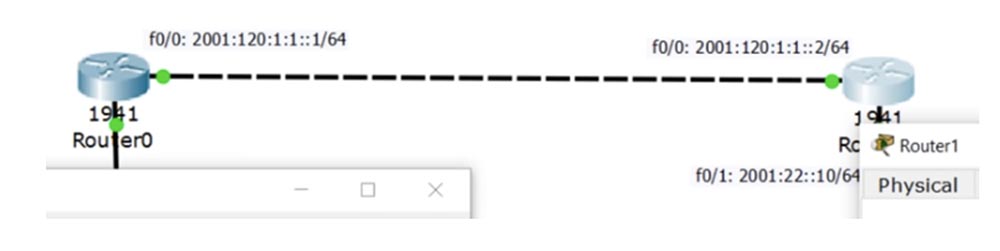
The GigabitEthernet 0/0 port is disabled, that is, it is in the down state, as shown by the red markers of the R0-R1 connection. The port of the second router is also marked with a red marker, because we have not yet started to configure it, but don’t worry, I will do this later. For now, let's go back to the settings of the g0 / 0 port and assign it the desired address with the ipv6 address 2001: 120: 1: 1 :: 1/64 command, without forgetting the no shutdown command. Then we go to the g0 / 1 interface and assign it the address with the ipv address 2001: 11 :: 10/64 command and also use the no shutdown command.
Let's move on to the second router R1 and configure it in the same way as we configured the router R0. In this case, the address 2001: 120: 1: 1 :: 2/64 will be assigned to the g0 / 0 interface, and the address 2001: 22 :: 10/64 to the g0 / 1 interface. After that, the color of the markers of both interfaces will change from red to green, indicating that they are connected to the network.
If we return to the first R0 router and look at the IPv6 interface parameters, we will see that we have configured both addresses - the Link Local address and the required address 2001: 11 :: 10.

To verify the connection, I ping the first router from the second, using the ping 2001: 120: 1: 1 :: 1 command in the CLI. Ping is successful because both routers are directly connected to each other. Now let's check whether it is possible to ping the Link Local address of the g0 / 0 interface of the first router, for this I use the ping command FE80 :: 290: 2BFF: FE52: 6901, after which the system asks to specify the Output interface. What does it mean?
If we look at the configuration of the interfaces of the two routers, we will see that both of these devices have the same Link Local address FE80 :: 290: 2BFF: FE52: 6901. This is completely normal. Packet Tracer shows that the address of the g0 / 1 interface is FE80 :: 290: 2BFF: FE52: 6902, but if you look at a real physical device or use the GNS3 program, we will see that this is the same IP address, because FE80 uses the same Link Local addresses. Therefore, to ping any IP address, we must indicate from which address and from which interface we will ping. Therefore, I specify Output interface: GigabitEthernet0 / 0 and ping succeeds.
Now I will try to ping the address FE80 :: 290: 2BFF: FE52: 6901 from the GigabitEthernet0 / 1 interface, and I am unable to do this. The fact is that the Link Local address is assigned to a specific connection, in this case it is a connection of the f0 / 0 interfaces of our two routers, and this address cannot be used in any other network segment. This is a very important point that you must remember.
Now let's move on to the commands used for troubleshooting. Before that, I used the show ipv6 interface brief command, and now I will enter the show ipv6 route command.
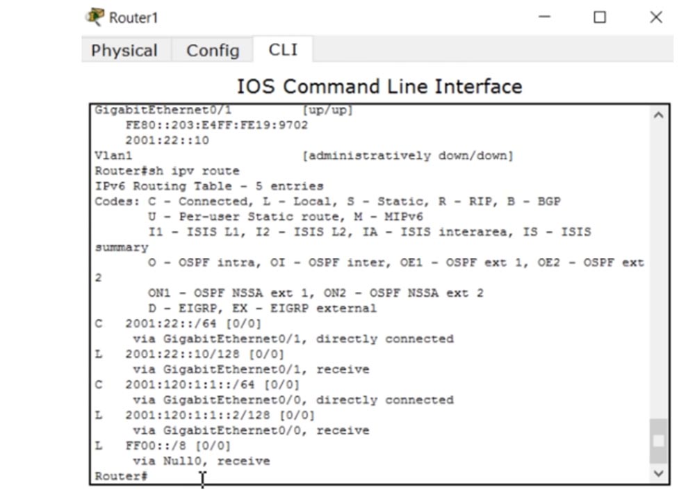
Remember that almost all the commands that we used for IPv4 are also applicable for IPv6, but with a mandatory version. Therefore, it will be easy for you to deal with the sixth version of the protocol if you have learned to work with the fourth. If you type the show ipv6 interface g0 / 0 command, you can see the status and settings of this interface. Here is the Global Unicast address and the affiliated multicast group address FF02 :: 1, FF02 :: 1: FF00: 2 and FF02 :: 1: FF19: 9701. As I said, multicast addresses start with FF and act like a radio station, so to tune in to their “channel”, you need to join this group. Moreover, any data packet transmitted over the network will be accepted by all devices that are “configured” to this group of addresses, that is, attached to this group. Next, we see the value of MTU, ICMP and other characteristics of this IPv6 interface.
So, for troubleshooting IPv6 problems, two commands are mainly used: show ipv6 interface brief and show ipv6 route.
Let's go back to the topology of our network to consider one more question. Can I ping PC1 from PC0? Let's try to do it. I enter the command line terminal of the first computer and enter the ping 2001: 22 :: 1 command. Ping fails for a very obvious reason. The fact is that the first router is not set a route between these two devices, so the connection does not work. When a packet from PC0 arrives at R0, it does not know how to deliver it to PC1, because it knows nothing about its network 2001: 22 :: 1/24. In order to ensure communication between the two computers, we must configure static or dynamic routing for the router.

We start by setting up a static route, and then move on to a dynamic one. As in the IPv4 settings, we use the ipv6 route command and get a hint with a range of possible addresses in the form X: X: X: X :: X / <0-128> IPv6 prefix. Next, I enter 2001: 22 :: 0/64 and get the following system prompt.
We must inform the first router about the existence of the network in which the second computer is located. To do this, he must be able to send the packet to the f0 / 0 interface of the second router. There are two ways to do this: we can specify the output interface or inform the first router of IPv6 the address of the next hop. We select the last option and type the ipv6 route 2001: 22 :: 0/64 2001: 120: 1: 1 :: 2 command. If we want to introduce an administrative distance, we can do it now.
Now R0 knows how to get to the network of the second computer. We do the same with the second router R1. I enter the global settings mode with the config t command and type ipv6 route 2001: 11 :: 0/64 2001: 120: 1: 1 :: 1.
Let's see if R0 can now ping PC1. We use the ping 2001: 22 :: 10 command and see that the first router confidently pings the second router. However, after entering the ping 2001: 22 :: 1 command, ping fails. Let's try to figure out what is the matter. I check the network settings of both computers and see that everything is in order here. What happened? The reason ping fails is because of IP routing.
I go into the settings of the first router and enter the ipv6 unicast routing command, then do the same with the second router. As you can see, after this the ping of PC0-PC1 is successful. So, in order to provide IPv6 routing, you must go into the router settings and enter the ipv6 unicast routing command. My mistake is that I have not done this before. So, we made unicast routing available, and now both devices can communicate with each other. This is how static routing is provided.
In order to provide dynamic routing, it is necessary to use the RIP protocol, which has the property of self-updating routing tables. This mechanism is called RIPng, or next-generation dynamic RIP routing. To use it, I will first remove all the static routing parameters, using the no ipv6 route command in the settings of both routers.
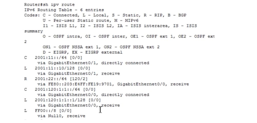
In order to view the routing table, I use the show ipv6 route command.
As you can see, now there is no information about the network of the second computer in it, the ping fails because the destination address is not available. R0, , , , PC0. RIP R0. int g0/0 ipv6 rip, WORD – , RIP. RIP IPv4 IPv6.
WORD NetworKing enable, ipv6 rip NetworKing enable. g0/0 ipv6. g0/1. , RIP IPv6, , RIP, NetworKing, .
, NetworKing , , .
, , RIP 2001:11::/64 FE80::203:E4FF:FE19:9701.
, , R0 , . , – IPv6 ipv6 unicast routing. . RIPng.
, , , . , IPv6, CCNA. , .
, . ? ? , 30% entry-level , : VPS (KVM) E5-2650 v4 (6 Cores) 10GB DDR4 240GB SSD 1Gbps $20 ? ( RAID1 RAID10, 24 40GB DDR4).
Dell R730xd 2 ? 2 Intel TetraDeca-Core Xeon 2x E5-2697v3 2.6GHz 14C 64GB DDR4 4x960GB SSD 1Gbps 100 $199 ! Dell R420 — 2x E5-2430 2.2Ghz 6C 128GB DDR3 2x960GB SSD 1Gbps 100TB — $99! . c Dell R730xd 5-2650 v4 9000 ?
As we learned from the previous lesson, IPv4 uses the automatic configuration of internal or private IP addresses (APIPA).
This mechanism is activated when a network client tries to contact a DHCP server to obtain an IP address, but for some reason cannot do this. In this case, the IPv4 device itself assigns itself a random IP address of the form 169.254.X.X. After that, it reports its APIPA address using broadcast broadcasting, and if no other device on the network has such an IP address, it keeps it for itself. Otherwise, the client generates a new address, randomly selecting the contents of the third and fourth octets, and again uses broadcast transmission.
To make it clear what I mean, let's move on to Packet Tracer. Take a computer, go into the IPv4 network settings and set the “Static” checkbox in the “IP Configuration” item. After that, the computer will try to obtain a DHCP address, but as we can see, the device is not connected anywhere and there cannot be any DHCP server that can assign an address to it. The computer, having not received any address, must assign it to itself. However, on the command line we see only the MAC address of the device, probably because I still need to connect the computer to the switch in order to create some kind of network. I add a switch to the circuit and connect it with a cable to our computer.
In the “IP Configuration” item of network settings, the DHCP checkbox is now checked, and technically the computer itself should try to assign an IP address. In the command window, you see that this is exactly what happened - the computer assigned itself an automatically configured random address 169.254.26.192, after which its interface marker changed color from red to green, that is, a connection was established between it and the switch.
So, the computer tried to access the DHCP server through the switch, did not receive a response, because the switch is not connected to any server, and started the IP address auto-configuration mechanism. This mechanism is activated in any local area network that is not connected to the DHCP server. For example, if you have 5 computers and a switch in the local network, as a result of auto-configuration, each of them will receive its own IP address, which allows you to communicate with each other on the local network.
Let's add another computer to our network, connect it to the switch, specify DHCP in the “IP Configuration” section of the network settings and through the command line execute the command PC> ipconfig. As you can see, the second computer assigned itself the address 169.254.167.182, which is in the range of valid APIPA addresses. Now both computers have IP addresses on the same local network, and the subnet mask 255.255.0.0 points to / 16, that is, both computers can communicate with each other without problems. If I ping PC0 at 169.254.26.192, we will see that both devices can communicate over the network.
Although today we are considering IPv6 rather than IPv4, this example is convenient for understanding the principle of autoconfiguration. It shows that in a local area network with automatically configured addresses, you can freely share files from the shared folders of different computers without the need for manual configuration of IP addresses.
We looked at IPv4 address autoconfiguration, but IPv6 also has autoconfiguration. However, the autoconfiguration mechanisms of two different versions of the IP protocol are significantly different from each other. Consider the situation using IPv4 - if we take the port of the router and assign it some IP address, and then we want to change it, the new IP address will simply wipe the old one without any trace. This is the difference between IPv4 and IPv6 - in the case of IPv6, the same interface can have multiple IP addresses. In IPv4, it is possible to assign a secondary IP address to an interface using the secondary command, however, in practice, only the primary address is used in all cases. In IPv6 there is no need to assign a secondary address, you will learn about this from the following slides, which will show the configuration of such an IP address. I’ll say that if you assign two IP addresses to one interface, both of them will take part in routing and the router will have access to both addresses.
When you assign an IP address to a router or any device running IPv6, for example, 2001 :: 1/64, a Link Local address is automatically created. As mentioned in the previous lesson, Link Local address is automatically generated by the device, assigned to the interface and starts with FE80. This means that this address is assigned only to this specific interface and cannot communicate with external networks, since it works only in this segment of the local network. At the same time, the unique 48-bit MAC address of the device is used as the basis of the IP address, divided in the middle into 2 parts by the FF: FE characters. This mechanism is known as generating IP addresses using EUI-64, which is an IEEE standard. EUI-64 adds another 16 bits to the MAC address unique to each device, turning it into a unique 64-bit IP address. This is the automatic configuration of the Link Local address over IPv6.
Back to Packet Tracer, where we configured computers using IPv4, and look at the IP configuration of PC0.
As you can see, there is both a Link Local IP address and an automatically configured IP address. However, the FE80 is part of the LAN address, and the remaining 4 octets of the IPv6 address are part of the host address. You see that just in the middle of this part of the host, FF: FE is present, creating a unique address FE80 :: 2EO: 8FFF: FE5A: 1AC0. Looking at this entry, you can determine that the unique MAC address for this device is 02EO: 8F: 5A: 1AC0. This address was automatically configured in EUI-64 format, which is a translation of the MAC address into a 64-bit IP address. The question is, can I create a Link Local address manually? Of course you can, and now we will try to do it.
Add a Cisco router to our scheme and assign it an IP address. To do this, I enter the global settings and type in ipv6 address, not just ip address, as is done for IPv4, and then type in the address 2001 :: 1/64.
As you can see, we can dial / 64, which is very convenient! In IPv4, we could also enter a slash, but the system did not pay attention to it. Next, I enter the no shutdown command and my favorite show ip interface brief, only for interface version 6 of the protocol I definitely indicate this in the form of not just ip, but ipv6. The difference is that for the sixth version of the IP protocol in all commands instead of ip you need to use ipv6. So, I enter the do show ipv6 interface brief command, and the system shows me the IPv6 interfaces.
You see both the address assigned by us 2001 :: 1/64, and the Local Link address located above, which was automatically generated by the system. In the middle of this address, you see FF: FE, which indicate formatting the address using EUI-64.
Let's go back to the g0 / 0 interface and add another address. As I said, if I enter a new interface address in the case of IPv4, it will simply rewrite the old address. In the case of IPv6, if I enter the new address 2002 :: 1/64 and then ask me to show me the interface parameters using the do show ipv6 interface command, we will see that both addresses are available to us - both old and new.
Suppose we want to change the Link Local address. To do this, I type the ipv6 address FE80 :: 1 command. Remember that you cannot use a slash in Link Local addresses, so I add the expression link-local to the command and enter the command to change the IP address of the local network FE80 :: 1 link-local. Then I ask the system to show the new interface parameters.
As you can see, the old Link Local address has been replaced with the new address, because the interface can have only one address like FE80 ::.
So we’ve looked at how Link Local addresses are automatically and manually assigned, and now we’ll find out what an automatic IPv6 address means.
Full IPv6 auto-configuration means we have a DHCP server. Just as with IPv4, in IPv6, this server simply assigns the IP address to the device that requests it.
This configuration is used when you do not want to manually assign an IP address to the interface and the DHCP server does this automatically. If you do not have a DHCP server and you do not want to enter the address manually, but want it to be generated automatically, you can turn to EUI-64 again. This means that everything that does not start with FE80 can be an IP address, you can freely use the address of the format 2001 :: _ EUI-64_, and this is a way to automatically configure the IP address. If we use IPv6 with the / 64 slash, this means that we are manually configuring the IP address.
Now I want to show you how the automatic configuration in the EUI-64 format occurs when entering the address we selected. To do this, I will go into the CLI settings of the router and configure the IP address of the sixth version. This is done in the same way as manually configuring an IP address.
To do this, I will type ipv address 2010 :: / 64 eui-64 and no shutdown sequentially, and I can not type ipv6 completely, because the letter v after ip is perceived by the system as indicating the 6th version.
Then I will ask you to show the interface parameters, and you see that the system generated the address 2010 :: 290: 2BFF: FE52: 6902, and part of the host address in this unicast address completely repeats the MAC address of the device used as part of the host address in Local Link Address FE80 :: 290: 2BFF: FE52: 6902.
Now let's look at how IPv6 is configured. The diagram shows 2 host computers, two switches and two routers, and now I will quickly configure them.
Let's move on to Packer Tracer and consider three aspects: IPv6 configuration - addresses, pinging of IPv6 devices and commands that are used to detect IPv6 problems.
On the network topology, I have already marked the IP addresses that need to be assigned to routers. I go into the PC0 network settings, disable the ability to use DHCP over IPv6 and manually configure a static IPv6 address.
To do this, I will dial the device address 2001 :: 11 :: 1/64 and the IPv6 address of the gateway, which is Router0. The slash is not used in this address, because we know exactly where the router is located.
Similarly, PC1 is configured. This is the usual network setup in Windows, so let's not focus on it.
Now let's move on to the more important part of the settings. To do this, I will delete the existing IP addresses of the R0 router using the ipv add command and look at the result using the do show ip interface brief command. As you can see, the operation was successful for the g0 / 0 interface, and now I will do the same for the g0 / 1 interface. As you can see, all previously assigned IP addresses are deleted.
The GigabitEthernet 0/0 port is disabled, that is, it is in the down state, as shown by the red markers of the R0-R1 connection. The port of the second router is also marked with a red marker, because we have not yet started to configure it, but don’t worry, I will do this later. For now, let's go back to the settings of the g0 / 0 port and assign it the desired address with the ipv6 address 2001: 120: 1: 1 :: 1/64 command, without forgetting the no shutdown command. Then we go to the g0 / 1 interface and assign it the address with the ipv address 2001: 11 :: 10/64 command and also use the no shutdown command.
Let's move on to the second router R1 and configure it in the same way as we configured the router R0. In this case, the address 2001: 120: 1: 1 :: 2/64 will be assigned to the g0 / 0 interface, and the address 2001: 22 :: 10/64 to the g0 / 1 interface. After that, the color of the markers of both interfaces will change from red to green, indicating that they are connected to the network.
If we return to the first R0 router and look at the IPv6 interface parameters, we will see that we have configured both addresses - the Link Local address and the required address 2001: 11 :: 10.
To verify the connection, I ping the first router from the second, using the ping 2001: 120: 1: 1 :: 1 command in the CLI. Ping is successful because both routers are directly connected to each other. Now let's check whether it is possible to ping the Link Local address of the g0 / 0 interface of the first router, for this I use the ping command FE80 :: 290: 2BFF: FE52: 6901, after which the system asks to specify the Output interface. What does it mean?
If we look at the configuration of the interfaces of the two routers, we will see that both of these devices have the same Link Local address FE80 :: 290: 2BFF: FE52: 6901. This is completely normal. Packet Tracer shows that the address of the g0 / 1 interface is FE80 :: 290: 2BFF: FE52: 6902, but if you look at a real physical device or use the GNS3 program, we will see that this is the same IP address, because FE80 uses the same Link Local addresses. Therefore, to ping any IP address, we must indicate from which address and from which interface we will ping. Therefore, I specify Output interface: GigabitEthernet0 / 0 and ping succeeds.
Now I will try to ping the address FE80 :: 290: 2BFF: FE52: 6901 from the GigabitEthernet0 / 1 interface, and I am unable to do this. The fact is that the Link Local address is assigned to a specific connection, in this case it is a connection of the f0 / 0 interfaces of our two routers, and this address cannot be used in any other network segment. This is a very important point that you must remember.
Now let's move on to the commands used for troubleshooting. Before that, I used the show ipv6 interface brief command, and now I will enter the show ipv6 route command.
Remember that almost all the commands that we used for IPv4 are also applicable for IPv6, but with a mandatory version. Therefore, it will be easy for you to deal with the sixth version of the protocol if you have learned to work with the fourth. If you type the show ipv6 interface g0 / 0 command, you can see the status and settings of this interface. Here is the Global Unicast address and the affiliated multicast group address FF02 :: 1, FF02 :: 1: FF00: 2 and FF02 :: 1: FF19: 9701. As I said, multicast addresses start with FF and act like a radio station, so to tune in to their “channel”, you need to join this group. Moreover, any data packet transmitted over the network will be accepted by all devices that are “configured” to this group of addresses, that is, attached to this group. Next, we see the value of MTU, ICMP and other characteristics of this IPv6 interface.
So, for troubleshooting IPv6 problems, two commands are mainly used: show ipv6 interface brief and show ipv6 route.
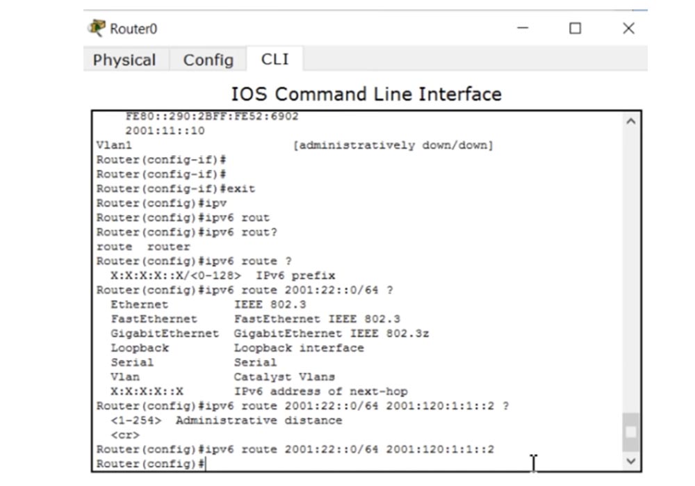
Let's go back to the topology of our network to consider one more question. Can I ping PC1 from PC0? Let's try to do it. I enter the command line terminal of the first computer and enter the ping 2001: 22 :: 1 command. Ping fails for a very obvious reason. The fact is that the first router is not set a route between these two devices, so the connection does not work. When a packet from PC0 arrives at R0, it does not know how to deliver it to PC1, because it knows nothing about its network 2001: 22 :: 1/24. In order to ensure communication between the two computers, we must configure static or dynamic routing for the router.
We start by setting up a static route, and then move on to a dynamic one. As in the IPv4 settings, we use the ipv6 route command and get a hint with a range of possible addresses in the form X: X: X: X :: X / <0-128> IPv6 prefix. Next, I enter 2001: 22 :: 0/64 and get the following system prompt.
We must inform the first router about the existence of the network in which the second computer is located. To do this, he must be able to send the packet to the f0 / 0 interface of the second router. There are two ways to do this: we can specify the output interface or inform the first router of IPv6 the address of the next hop. We select the last option and type the ipv6 route 2001: 22 :: 0/64 2001: 120: 1: 1 :: 2 command. If we want to introduce an administrative distance, we can do it now.
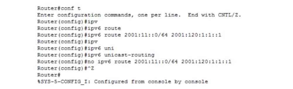
Now R0 knows how to get to the network of the second computer. We do the same with the second router R1. I enter the global settings mode with the config t command and type ipv6 route 2001: 11 :: 0/64 2001: 120: 1: 1 :: 1.
Let's see if R0 can now ping PC1. We use the ping 2001: 22 :: 10 command and see that the first router confidently pings the second router. However, after entering the ping 2001: 22 :: 1 command, ping fails. Let's try to figure out what is the matter. I check the network settings of both computers and see that everything is in order here. What happened? The reason ping fails is because of IP routing.
I go into the settings of the first router and enter the ipv6 unicast routing command, then do the same with the second router. As you can see, after this the ping of PC0-PC1 is successful. So, in order to provide IPv6 routing, you must go into the router settings and enter the ipv6 unicast routing command. My mistake is that I have not done this before. So, we made unicast routing available, and now both devices can communicate with each other. This is how static routing is provided.
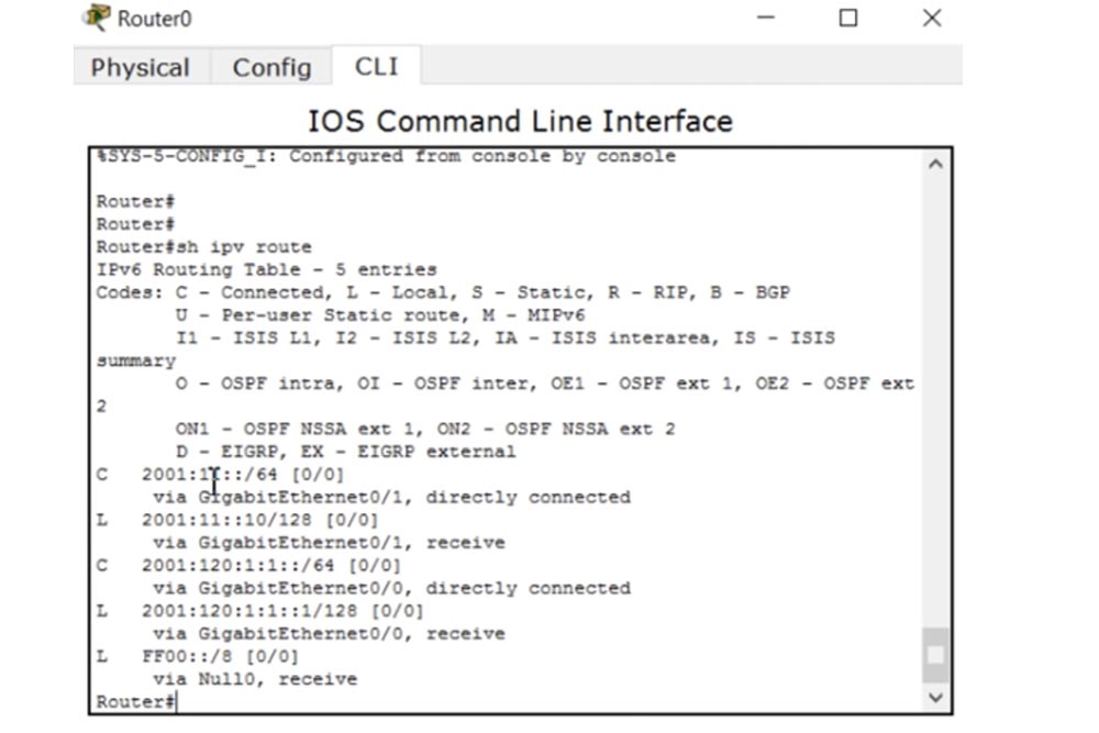
In order to provide dynamic routing, it is necessary to use the RIP protocol, which has the property of self-updating routing tables. This mechanism is called RIPng, or next-generation dynamic RIP routing. To use it, I will first remove all the static routing parameters, using the no ipv6 route command in the settings of both routers.
In order to view the routing table, I use the show ipv6 route command.
As you can see, now there is no information about the network of the second computer in it, the ping fails because the destination address is not available. R0, , , , PC0. RIP R0. int g0/0 ipv6 rip, WORD – , RIP. RIP IPv4 IPv6.
WORD NetworKing enable, ipv6 rip NetworKing enable. g0/0 ipv6. g0/1. , RIP IPv6, , RIP, NetworKing, .
, NetworKing , , .
, , RIP 2001:11::/64 FE80::203:E4FF:FE19:9701.
, , R0 , . , – IPv6 ipv6 unicast routing. . RIPng.
, , , . , IPv6, CCNA. , .
, . ? ? , 30% entry-level , : VPS (KVM) E5-2650 v4 (6 Cores) 10GB DDR4 240GB SSD 1Gbps $20 ? ( RAID1 RAID10, 24 40GB DDR4).
Dell R730xd 2 ? 2 Intel TetraDeca-Core Xeon 2x E5-2697v3 2.6GHz 14C 64GB DDR4 4x960GB SSD 1Gbps 100 $199 ! Dell R420 — 2x E5-2430 2.2Ghz 6C 128GB DDR3 2x960GB SSD 1Gbps 100TB — $99! . c Dell R730xd 5-2650 v4 9000 ?
All Articles