ShIoTiny: small automation, the Internet of things, or “six months before the holidays”
Key points or what this article is about
Since the interests of people are different, and people have little time, then briefly about the content of the article.
This article is an overview of the controller project with a minimum price and the possibility of visual programming through a WEB browser.
Since this is a review article aimed at showing "what you can squeeze out of a penny controller," you should not look for deep truths and detailed algorithms in it.
The motivation, ideas and results of building a controller based on the ESP8266 WiFI chip are considered.
A warning
I did not want to write this article. I'm not a fan of writing articles at all. It is necessary to think and moreover - a lot. To think how to write so that the number of misunderstoods is minimized. To think how not to go to extremes. And much more to think about.
But friends said that since my efforts in the field of IoT and other small automation are interesting to them, then they can be interesting to others to the general public. Well, where is the audience going to who is interested in this? Of course, on a habr. And here I am. Old reader and new writer.
For errors, inaccuracies, typos, non-modern style of presentation and other things that may not please the reader, I do not bear any responsibility. Read at your own risk.
I also immediately warn that I will not explain what MQTT, WiFi and UDP multicast and other things that are not directly related to the topic. Some links are at the end of the article.
The birth of an idea or some lyrics
Well, life is not a simple thing, and His Majesty Chance plays an important role in it. So I want to share how random events, multiplied by regular laziness, resulted in a rather interesting controller design based on ESP8266.
Everything began rather casually: I wanted to build a control system for the water supply system and watering the garden beds in the country.
But about, since I can fully engage in pipe-tanks-cranes only on vacation, before which there was even more than six months - everything was limited to discussion at work with colleagues and friends-comrades in an informal setting.
The topic of “small automation” or, as is customary to say in “these your school-hacker-hacker schoolchildren” - the topic of IoT - the Internet of things - has been of interest to me for a long time. Long before the advent of the Internet as such in widespread use.
Even as a child, I wanted things to do something “themselves.” And it is desirable that I can control them somehow from a distance. But at that time (the 80s, the beginning of the 90s of the last millennium) this was difficult. The Internet was not widely available anywhere in the world, as there were nowhere and cell phones, tablets and even LCD-displays and USB-flash drives. So I had to be limited to "light switches on the clap" and the simplest radio remote controls. But for those times and that age, it was nice and interesting.
But this is the past. Nonche in the courtyard of the XXI century. And everyone has a smartphone in their pocket, the Internet is almost everywhere where it is necessary and not necessary, and the database of available electronic components is now such that 15 years ago the ordinary inhabitant of planet Earth did not even dream of it.
Therefore, having decided to mold a controller for water affairs in the country, I turned my eyes to the ESP8266 chip.
First off, this chip is cheap. And if one controller is not enough - you can put two, three or five. Secondly, it has WiFi on board. That is, you can watch what is happening via the Internet and even control the process from any smartphone. Of course, you need an access point with Internet access, but this is not a problem. Anyway, it is almost everywhere or is about to be, including - and in my country house.
Having plunged into the wonderful world of projects for ESP8266, I was surprised to find that, despite the awesome capabilities of this chip, projects on it, with rare exceptions, are divided into two types: these are extremely primitive programs like “click on the reels from the smartphone and look at the state temperature sensor via the Internet ”; or good and solid interpreters of JavaScript or Lua, but unfortunately, they eat almost all the memory and do not allow doing something serious.
My first idea was as simple as a pancake - to write a simple pump control program based on the state of the sensors and that’s all. But, like a shredded kalach in terms of jumping on the rake of introducing different systems, I realized that I would definitely not be able to foresee all the bends of the algorithm that I would like or would need to straighten out during the construction of the water supply-irrigation system.
D working out the program in the country, in a dark barn - is not very convenient. And you have to.
What is the way out? Of course, the first thing that came to my mind was to make the algorithm customizable. One of my colleagues gave a lot of advice - what to configure and how. With this, he chopped off my first idea in the bud. Thanks to him. If he hadn’t deployed before my eyes the number of parameters that I would need to configure, I probably wouldn’t refuse this option: make an algorithm settings page.
But the terrifying picture of the number of tuning parameters, and even influencing one another - sobered me up. Once again, I realized that nothing could be foreseen ...
I will make a reservation right away: I'm lazy. Very lazy! I am frankly lazy to rewrite the program every time. Therefore, the task arose - how to quickly and easily set an algorithm, preferably without programming? Moreover, this algorithm will be quite complicated; will have a lot of parameters; It will be individual for my case and unsuitable for others. And I really want to make the device more or less universal ...
Since since there was still about six months before the vacation and all pipe-work, I decided to take my time to think: how to make it convenient and beautiful? How to program without programming? How to do without a trillion of parameters that can be changed when setting up?
As usual, everything was already thought up before us: I realized that I want to draw an algorithm in the form of action squares and connect them with communication lines that show where and where the data is flying from. Well, poking in the box, I want to be able to configure some of its individual parameters.
And the act of setting the algorithm, drawing it with squares is not new. Such systems were back in the 80s; there’s a super-popular NodeRed system, which is well known to those who have already joined the world of small automation / IoT.
But this is bad luck: such systems are designed for “large PCs”. At worst, on the Raspberry PI. But not on the ESP8266, which has only a few tens of kilobytes of RAM and there is no OS!
How to be? And there are only two ways out: to write and draw a program on a "large PC" or laptop, and then to transfer it in some form to ESP8266 or try to "cram the unwelcome" into the ESP8266 controller itself.
Therefore, the maximum program I had was this: to program your controller, there should be no need for anything except a laptop with a WEB browser! That is, a laptop with a WEB browser and my controller - this should be enough to fully configure and write-draw control programs.
And , as it turned out, it was quite possible to realize this!
I will not bore you with all the details of project development. I can only say that on the basis of the words that came to my mind and language during the development process, it would be possible to compile a separate “ Dictionary of Profanity of Electronic Industry Workers ”. But everything is behind. More precisely, not all, but the first, most difficult stage, when it is not clear - will your idea be to live or is it just nonsense of a gray gelding on a moonlit night.
I will share the result of what came out and is called the “ShIoTiny Controller” .
And what happened?
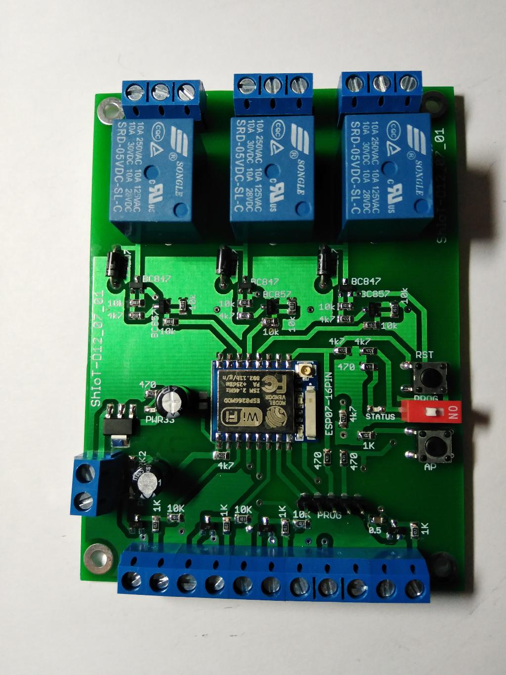
The hardware of the ShIoTiny controller is standard and simple: three inputs designed for dry contact sensors (buttons, reed switches, they are also water level sensors in the tank), one ADC input, one input for connecting a temperature and humidity sensor like DHT22 or similar . And finally, three outputs in the form of switching relays for 220V, 1 Amp. The relay says 10A, but I’m a realist and I won’t let them through the 10A amp board. And to control the starters of the pumps and 1 Amp is enough. All this is powered from a power source with a voltage of 5 to 9 volts.
Of course, I added the temperature sensor just like “Schaub was”, but on the ADC there were hopes to measure the voltage of the mains. Is it not enough?
Of course, all the inputs, except the input for connecting DHT22, have protection from resistors and diodes: I had no desire to burn ESP8266, and diodes and resistors cost only a few cents.
A photo of the finished product can be seen at the beginning of the article. I ordered several of these boards - what if I burn it or will I have to cut the paths and legs?
But, fortunately - did not have to.
The product is, of course, beauty and greatness. But for convenience, the following is a drawing diagram of the connection to the board simulators of sensors and actuators.

In place of level sensors - buttons Input1..3, instead of starters - LEDs connected to the relay Relay1..3. Well, a variable resistor on the ADC to simulate the input voltage.
When the relay is off, the red LED is on. And when turned on - green. So I debugged on the table.
In addition to all this, there is a power connector on the left of the board, and two service buttons on the right: Reset and AP. Well, a DIP switch that puts the device into programming mode. The programming connector ESP8266 via USB-UART adapter is also available.
Some explanations for the buttons. What is Reset - and so it is clear. But the AP button is needed in order to put ShIoTiny into open access point mode (configuration mode or Config Mode). Why is this needed? Well, for example, you messed up with the network settings and want to change them. Press the AP button for a few seconds (until the beautiful blue LED lights up). Then, take your smartphone or laptop, turn on WiFi and see there an open access point with the name esp_8266_xxxx and connect to it. Then go to the browser of your smartphone or laptop and type in the address bar: 192.168.4.1. If everything is in order, then you will be taken to the ShIoTiny controller page and you can configure it in a new way.
As we see, hardware is nothing complicated. Therefore, about the software part .
In all implementation hops, I will describe, but then. Someday. And today I will consider the software only "outside", that is, from the point of view of the user - myself or another, who risked using my craft (there are such stuntmen).
From the user's point of view, the device is an HTTP server that is accessible via WiFi. All settings, programming and so on - is done using a WEB browser.
And so, we went to the controller page. What do we see? And we see the tab “Control and status”, which shows the current status of the devices used: inputs, outputs, ADC, DHT22. In addition, the connection parameters to the access point are shown (if we work in the mode of a WiFi station); access point settings (if we work in WiFi-access point mode) or both. Well, in addition, the connection parameters with the MQTT broker are shown if the MQTT protocol is used.
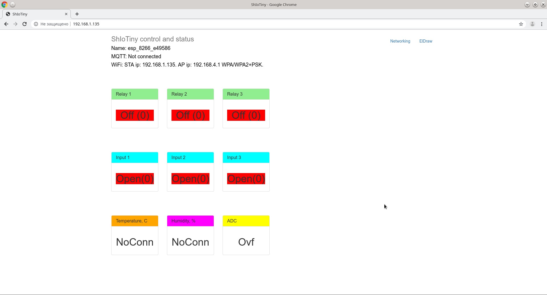
To see, nothing special and interesting. There’s nothing to press! Although ... There are two more tabs! Networking Networking and ElDraw Scheme Editor .
You guessed it, Networking is setting up a network, but not just that. It has a couple more interesting parameters. “Poke” on the Networking tab and see about what is shown in the figure there.
Configuring the access point name and password for each of the modes - WiFi stations and WiFi access points. Everything seems to be clear. As well as the purpose of the Scan WiFi button, it is completely transparent.
But the drop-down list "ShIoTiny mode" requires clarification. The fact is that I could not decide what mode it would be more convenient for me to work in. And therefore, provided for 5 modes of operation of the device.

We list briefly these operating modes.
Config mode - configuration mode. This is the open access point mode with a fixed address 192.168.4.1 and the name esp_8266_xxxx.
Station mode - the mode of the WiFi station connected to your access point.
AP mode - closed access point mode. You set the name and password yourself.
AP + Station mode is the simultaneous inclusion of AP mode + Station mode.
Single mode - work without connecting to a network at all. A lone controller carrying its heavy share ...
In any of the modes except “Config mode” , you can block the WEB page by checking the “Lock Web in Station mode” checkbox. This is a type for security reasons.
The settings are MQTT-obvious: server, port, password, open connection or SSL . I will not dwell here in detail.
In addition to everything else, the ShIoTiny controller can send and receive multicast-specific packets. Its settings are also obvious: group address and port.
Of course, if you describe all the nuances of the settings, you get a separate article, but this is not included in my plans.
And so, with the Networking tab, everything is more or less clear. Let's move on to the main chip of the controller - the editor of the program schemes ElDraw .
By tapping the ElDraw tab, we will see something like the following. Of course, if the device does not have a loaded circuit, then the circuit field will be empty.
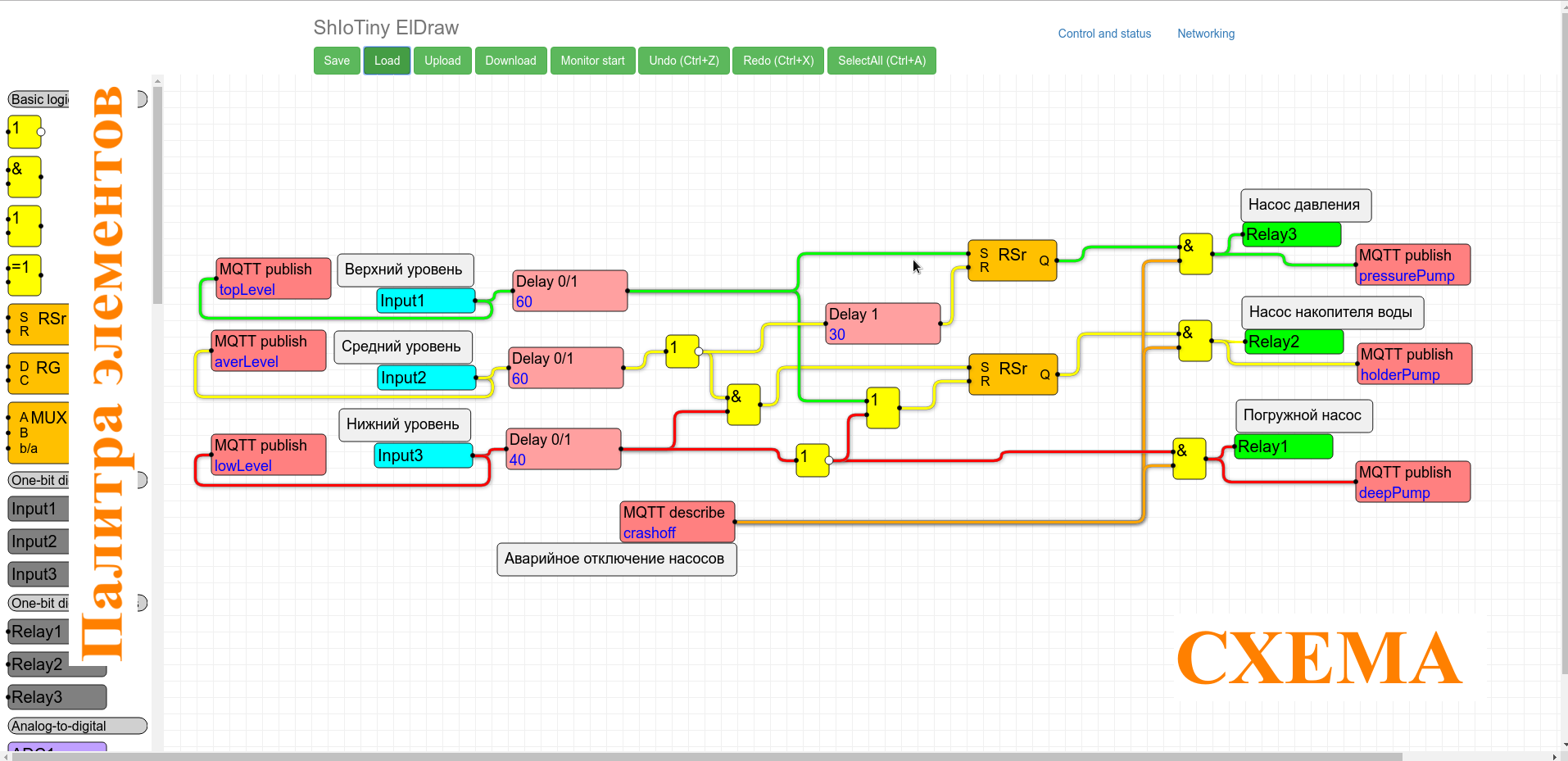
On the left is a palette of elements or nodes (nodes).
On the right, a schema field or simply a “schema”.
From the top - buttons for loading and unloading to disk and to the device, as well as editing buttons.
For those who have worked with editors, management is generally obvious. We need to add an element to the diagram - take it with the mouse and drag it from the palette to the diagram. It is necessary to remove the element or link from the diagram - poke on it or on it with the mouse and press the DEL key. We need to connect the elements - we take the input of one element and connect it to the output of another.
There is still scaling (SHIFT + mouse wheel). Unfortunately, there is no way to copy elements and groups of elements. But it does not interfere much.
In addition, for reasons of logic, the input of a node can only be connected to one output of another node. But the output of the node is with several inputs of other nodes. The inputs are always on the left of the nodes. The outputs are always on the right.
What capabilities do we have for implementing algorithms?
In opportunities - quite extensive. The palette contains nodes representing all the hardware of the ShIoTiny controller: inputs, relays, ADCs, DHT11 / 22.
There are logical and arithmetic nodes for data processing.
So that we can work with the device via the Internet, there are nodes for subscribing and publishing parameters to the MQTT broker.
If we want several ShIoTiny controllers to exchange information with each other - you can use the nodes for transmitting and receiving parameters using the UDP multicast protocol.
To this rum, there are timer nodes; event processing control nodes.
I will give a few examples. For example, do you want temperature and humidity data to be published on the MQTT server every 30 minutes? There is nothing easier. Draw like that.

Well meme button "Upload". Everything!
If you have correctly configured the connection with the MQTT broker on the Networking tab, that's all!
Every half hour, the temperature will be published on the broker under the topic / T, and humidity - under the topic / H. Or, if you ask your own topic names, then under them.
Question: Why is 18,000 30 minutes? Because all times are measured in tenths of a second.
Now you want to add to this circuit the ability to turn on Relay1 relay via the Internet, and even for a certain time? No problem. Draw up like that.
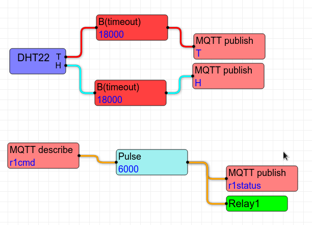
About five, click the button "Upload". Everything! Now, in addition to the fact that every half hour, temperature and humidity will be published on the MQTT broker, it will be possible to turn on Relay1 relay. Yes, not just turn it on, but for exactly 10 minutes. You can enable the relay by publishing the topic / r1cmd set to 1. And the real state of the relay will be published in the topic / r1status.
In am I want to not only turn on, but also turn off the relay ahead of time? Yes, as you say. The figure below shows how to do it!

Is the principle clear? You just draw the algorithm with the mouse! And write a little settings: time, topic name and all. This is much clearer than writing a bunch of code.
By the way , highlighting links in different colors is not a “photoshop” - this is one of the functions of the editor. You can colorize the links as you wish, so as not to get confused in them.
But oh and that's not all! In order to debug the algorithm, there is a “Monitor start” button. Strange as it may seem, it turns on the “monitor” mode. In this mode, the state of all outputs of all nodes is periodically read from the ShIoTiny controller and displayed on the circuit. Roughly as in the figure below.

That is, we can see in “almost real time” what we have at the input and output of each node. It helps a lot when something is not clear.
There are still many “chips and features” that I would like to describe, and my conscience will not allow you to spend your time on them in one article. The main realized idea is already clear: a minimum of configurable parameters - a maximum of visibility.
A spoon of tar
Of course, I want there to be no fly in the ointment, but the world is not perfect. Both my editor and my controller are not perfect. I discovered two main features that I have not yet been able to eliminate.
Firstly, sometimes glitches occur during group movement of elements. But this does not greatly interfere with the work. More like a feature than a bug.
And secondly, under certain conditions, after loading the circuit into the device using the “Upload” button, it restarts. This does not interfere with living, but the editor page needs to be updated.
Conclusion
I hope you like the idea of drawing algorithms instead of writing programs. So random thoughts, ideas, and debates sometimes give rise to viable developments for themselves.
But about, in my opinion, the volume of the article has outgrown all reasonable limits. So I’m done for today.
I only want to say that there are only a few weeks left before the vacation and I’m quite ready to move from debugging the controller at the table to debugging it “in the field”.
If anyone is interested in my ideas or development details - write to the soap: shiotiny@yandex.ru
I will always be glad to receive comments and criticism, if, of course, in the case.
Waiting for your feedback, comments and suggestions.
Links, references and parcels
ESP8266
Wifi
MQTT
UDP Multicast
At the request of workers
I spread raw documentation and firmware (binar).
https://github.com/shiotiny/ShIoTinyBin
Firmware: https://github.com/shiotiny/ShIoTinyBin/blob/master/bin/esp-07-shiotiny.bin
Scheme: https://github.com/shiotiny/ShIoTinyBin/blob/master/doc/esp-07-shiotiny.png
Full instructions: https://github.com/shiotiny/ShIoTinyBin/blob/master/doc/ShIoT-esp8266-01_obzor.pdf
The instruction "how to sew" in the same place.
All Articles