SkyRC B6 Nano Charger Review & Test
SkyRC B6 Nano is a universal charger that provides rechargeable batteries of various electrochemical systems. The article contains technical information and will be useful to specialists in the field of using chargers and rechargeable batteries, as well as to users when choosing or operating chargers. The device was purchased in 2019.
The article consists of three parts. In the first part, the results of checks of the main technical characteristics of a battery charger on battery equivalent are presented. The second part shows the results of testing conducted on real batteries. The third part describes the advantages and disadvantages of the SkyRC B6 Nano device.
Figures 1 and 2 show photos of the SkyRC B6 Nano charger.
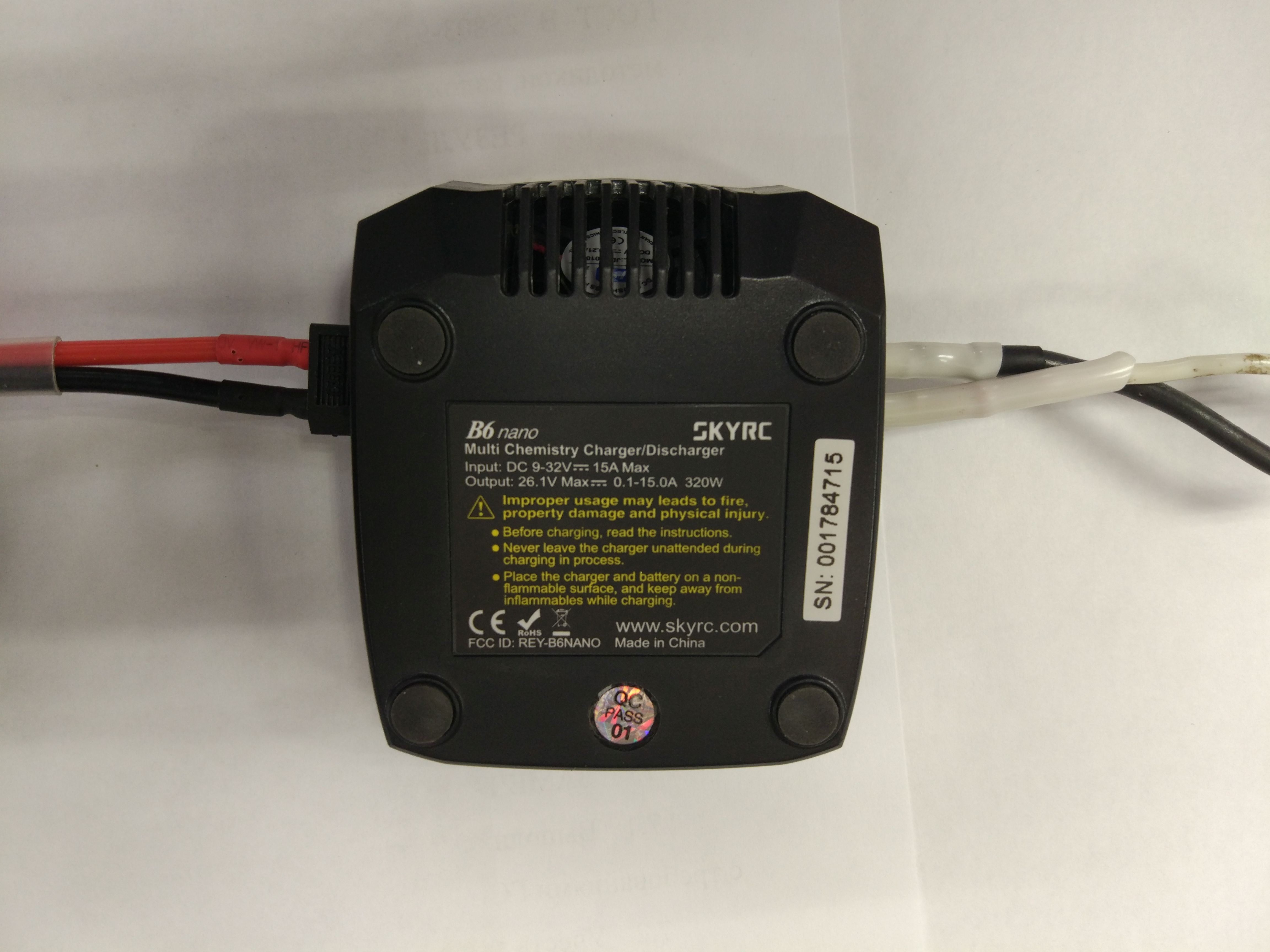
Picture 1
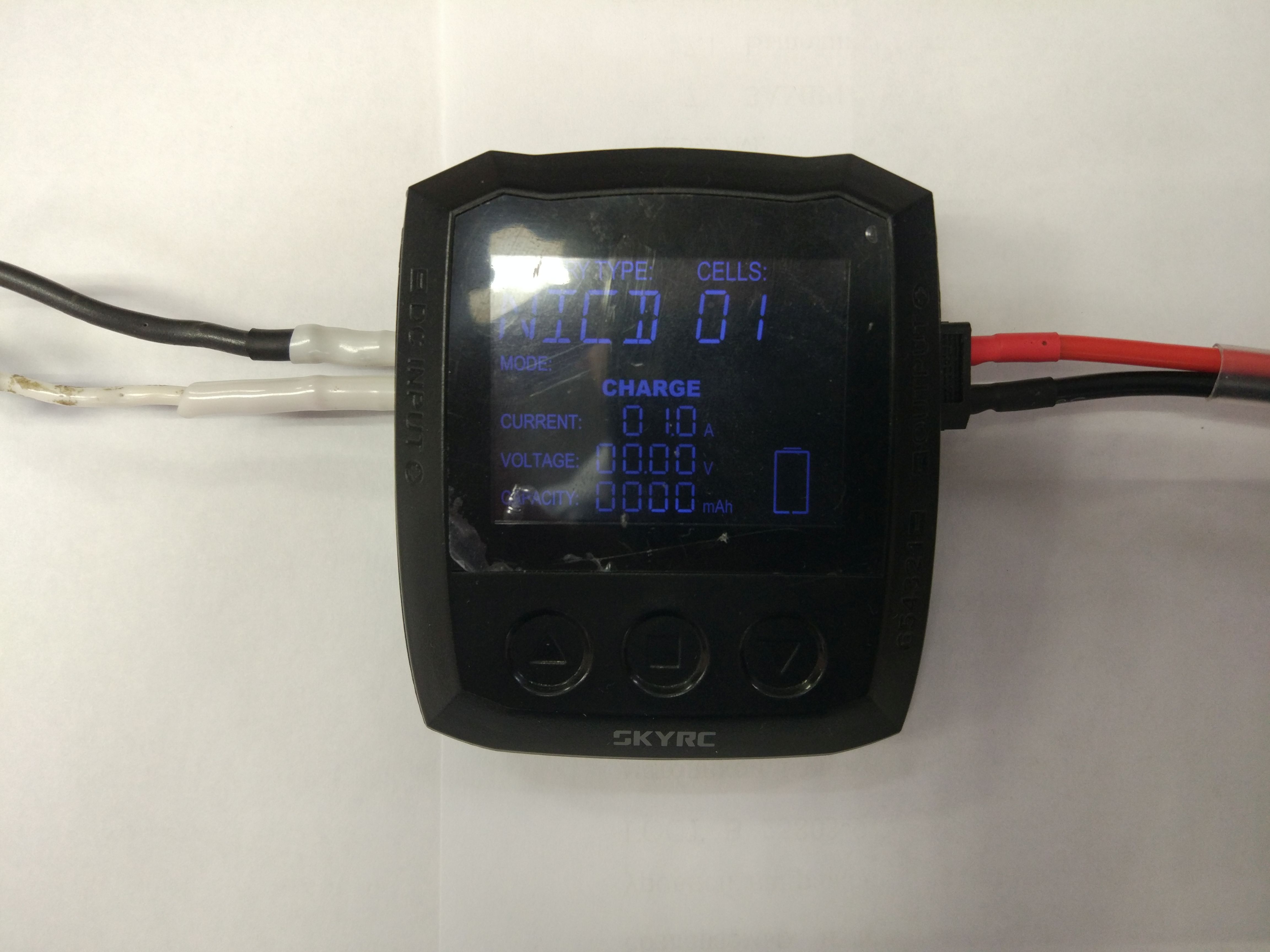
Figure 2
Part 1. Checking the main specifications of the charger
The tests were conducted on battery equivalent. During the tests, the checks listed in table 1.1 were carried out.
Table 1.1 & Tested parameters
| No. | Verification Name | Test results
(item number) |
|---|---|---|
| one | Check discharge current | paragraph 1.1 |
| 2 | Checking the criterion for the voltage of the end of the discharge in the service mode "Discharge" | paragraph 1.2 |
| 3 | Charge current test | paragraph 1.3 |
| four | Check voltage stabilization of the second stage of charge | Section 1.4 |
| five | Checking the criterion for the termination of the charge in current
charge stages | Section 1.5 |
| 6 | Checking the current consumption by the battery charger when the power is off | Section 1.6 |
| 7 | Checking the criterion for the end of charge according to "Delta-peak Sensitivity for NiMH / NiCd" | Section 1.7 |
| eight | Checking the operation of the device with an input voltage of 9 to 32 V | Section 1.8 |
| 9 | Checking the possibility of charging deeply discharged batteries | Section 1.9 |
Below are the test results.
1.1 Checking the discharge current
Figure 1.1.1 shows graphs of correspondence between the reference value of the discharge current (installed) and measured (real) at various voltages on the battery. Input voltage 12 V.

Figure 1.1.1 - Graphs of compliance of the reference (set) value of the discharge current and the measured (real) voltage for the battery 3.7 V, 11.1 V, 22.2 V.
The discharge current is limited when a power of 5 W is reached, as stated by the manufacturer of the charger (see Figure 1.1.1). So, for a single-cell LiPO battery with a voltage of 3.7 V, the current is limited to (1.2 - 1.3) A, for a three-cell LiPO battery with a voltage of 11.1 V - (0.4 - 0.5) A, for a six-cell LiPO battery with a voltage of 22.2 V - (0.2 - 0.25) A. For a single-cell NiMH or NiCd battery, a current discharge with a maximum value of 3 A is permissible. Deviation of the measured discharge current from the set value for a single-cell NiMH battery at a current 0.1 A was 50%, at 0.3 A - 11%, for other values in the current range 0.6 - 3.0 A - does not exceed 5.5%.
1.2 Checking the criterion for the voltage of the end of the discharge in the service mode "Discharge"
As a result of testing, it was found that the deviation of the discharge end voltage from the set value at a discharge current of 1.0 A does not exceed 3.5%.
The discharge voltage parameters are set from the mobile device using the SkyCharger program in the following ranges (step "settings" 0.01 V):
| Electrochemical type of battery | Lipo | Lion | LiFe | LiHV |
|---|---|---|---|---|
| Allowable range of voltage reference during discharge, V / Cell | 3.0-3.3 | 2.9-3.2 | 2.6-2.9 | 3.1-3.4 |
1.3 Checking the charge current
Figure 1.3.1 shows graphs of correspondence between the reference value of the charge current (installed) and real (measured) at various voltages on the LiPO battery. Input voltage 24 V.

Figure 1.3.1 - A graph of the reference value of the charge current (set) and real (measured) when the battery voltage is 3.7 V, 11.1 V, 22.2 V.
Deviation of the measured charge current from the set value at the input voltage
24 V in the current range 0.1 - 15 A for LiPO batteries 3.7 V, 11.1 V, 22.2 V does not exceed 2.8%.
1.4 Check the voltage stabilization of the second stage of charge
Table 1.4.1 shows the voltage data measured at the battery terminals during the transition to the second charge stage at a current of 7.5 A in the “Charge” service mode.
Table 1.4.1 - Data on the voltages during the transition to the second charge stage in the “Charge” service mode
| Electrochemical type of battery | Lipo | Lion | LiFe | LiHV |
|---|---|---|---|---|
| Reference (set) value of the stabilization voltage of the second charge stage, V / Cell | 4.2 | 4.1 | 3.6 | 4.35 |
| Voltage value displayed on the charger indicator | 4,200 | 4,100 | 3,600 | 4,350 |
| The real (measured) value of the stabilization voltage of the second charge stage at the battery terminals | 4,070 | 3,986 | 3,533 | 4,249 |
The deviation of the measured voltage of the second charge stage at the battery contacts from the set value when switching to the second charge stage is 120 - 130 mV at a current of 7.5 A. This is due to a voltage drop on the wires and contacts, and the difference increases with an increase in the charge current. By the end of the charge, due to a decrease in the charge current, the difference decreases and does not exceed ± 50 mV / cell. According to the battery manual, the deviation voltage must not exceed ± 50 mV / cell. This deviation leads to a slight increase in charge time, because when switching to the second stage of the charge, the voltage due to a drop in the wires and contacts is less than the specified value, but by the end of the charge it reaches the specified value.
1.5 Verification of the criterion for the termination of charge by current in the second stage of charge
The charge is completed at a current of 0.2 - 0.75 A for LiPO, LiIon, LiFe and LiHV batteries.
1.6 Checking the current consumption of the charger from the battery when the power is off
When connecting the battery to the charger with the power off, the internal memory circuits consume current from the battery. This current can completely discharge the battery.
As a result of testing, it was found that the current consumption of the SkyRC B6 Nano device from the battery is 0.7 - 0.8 mA. So, if the battery is left with a capacity of 1 Ah for seven days, the battery will be discharged to the internal circuit of the charger by 0.13 Ah. The current consumption is of little importance.
1.7 Checking the criterion for the end of charge according to the "Delta-peak Sensitivity for NiMH / NiCd"
Table 1.7.1 shows the data on checking the operation of the criterion for the end of charge “Delta-peak Sensitivity for NiMH / NiCd” for a single-cell NiCd battery, in table 1.7.2 - a ten-cell NiCd battery.
Table 1.7.1 - End of charge according to “Delta-peak Sensitivity for NiMH / NiCd” to “Charge” mode for a single-cell battery
| Electrochemical type of battery | NiCd (1S) |
|---|---|
| Reference (set) value "Delta-peak", mV | ten |
| Shutdown according to "Delta-peak" at a charge current of 7.5 A, mV | No disconnection occurred |
Table 1.7.2 - Check "Delta-peak Sensitivity for NiMH / NiCd" in the "Charge" mode for a ten-cell battery
| Electrochemical type of battery | NiCd (10S) |
|---|---|
| Reference (set) value "Delta-peak", mV | 100 |
| Shutdown according to "Delta-peak" at a charge current of 7.5 A, mV | No disconnection occurred |
The charger did not complete the charge according to the Delta-peak criterion for both single-cell and ten-cell NiCd and NiMH batteries. Disabling according to the Delta-peak criterion did not occur.
1.8 Checking the operation of the device with an input voltage of 9 to 32 V
Table 1.8.1 and 1.8.2 show data evaluating the performance of the charger at various supply voltages. LiPO battery charge in “Charge” service mode. The setting of the maximum charge current and its deviation from the set value at various input supply voltages are evaluated as a device operability parameter.
The maximum charge power in accordance with the instruction manual (Instruction Manual Version 1.20) is 320 watts.
Table 1.8.1 - Checking the charger operation with an input voltage of 9 to 32 V with a battery power consumption of 246 W
| Input voltage, V | The set value of the charging current, A | Battery voltage (4S), V | Power consumed by the battery, W | The measured value of the charging current, A | Deviations of the charge current,% |
|---|---|---|---|---|---|
| 9 | 15 | 16,4 | 246 | * | * |
| 12 | 15 | 16,4 | 246 | 10.56 | 29.6 |
| 15 | 15 | 16,4 | 246 | 13.08 | 12.8 |
| 18 | 15 | 16,4 | 246 | 15.06 | 0.4 |
| 21 | 15 | 16,4 | 246 | 15.07 | 0.4 |
| 24 | 15 | 16,4 | 246 | 15.13 | 0.8 |
| 27 | 15 | 16,4 | 246 | 14.9 | 0.6 |
| thirty | 15 | 16,4 | 246 | 15.02 | 0.1 |
| 32 | 15 | 16,4 | 246 | 15.09 | 0.6 |
* Error "ERR 08" voltage below 9 V
Table 1.8.2 - Checking the battery charger with an input voltage of 9 to 32 V at a battery power consumption of 315 W
| Input voltage, V | The set value of the charging current, A | Battery voltage (4S), V | Power consumed by the battery, W | The measured value of the charging current, A | Deviations of the charge current,% |
|---|---|---|---|---|---|
| 9 | 15.0 | 21.0 | 315 | * | * |
| 12 | 15.0 | 21.0 | 315 | 8.6 | 42.0 |
| 15 | 15.0 | 21.0 | 315 | 10.9 | 27.0 |
| 18 | 15.0 | 21.0 | 315 | 13.71 | 8.6 |
| 21 | 15.0 | 21.0 | 315 | 14.78 | 1.4 |
| 24 | 15.0 | 21.0 | 315 | 15.02 | 0.1 |
| 27 | 15.0 | 21.0 | 315 | 15.7 | 4.6 |
| thirty | 15.0 | 21.0 | 315 | 15,2 | 1.3 |
| 32 | 15.0 | 21.0 | 315 | 15.04 | 0.3 |
* Error "ERR 08" voltage below 9 V
Figure 1.8.1 shows graphs of the dependence of the charge current on time when the supply voltage changes from 14.5 to 12.2 V. During the charging process, the input supply voltage was lowered from 14.5 to 12.2 V.
Figure 1.8.1 - Graphs of the dependence of the charge current on time when the voltage of the power supply changes (voltage on the battery is 3.7 V, the set charge current is 7.5 A).
It was found that the charger with an output power of 246 W on the battery produces the declared characteristics only with a supply voltage of 18 V and above, at 315 W it gives the declared characteristics only with a supply voltage of 24 V and above. It should also be noted the slow response of the regulator to external influence, i.e. the charge current returned to its previous value after changing the input voltage was 36 seconds, the charge current deviation was 1.9%. Thus, this charger requires a stable power source, as constant and sharp changes in the input voltage lead to a change in the charge current for a long time, which, ultimately, can lead to battery failure.
1.9 Checking the possibility of charging deeply discharged batteries
Table 1.9.1 shows the data on the minimum battery voltage at which a charge is possible, i.e. at a given or higher voltage, the charger “sees” the battery and goes into charge.
Table 1.9.1 - The minimum voltage per element at which it is possible to start the device on a charge.
| Electrochemical type of battery | Lipo | Lion | LiFe | LiHV | Nicd | Nimh | Pb |
|---|---|---|---|---|---|---|---|
| Minimum voltage per cell, V | 2.80 | 2.80 | 2.40 | 3.00 | 0.40 * | 0.40 * | 1,60 |
* value does not change with increasing number of batteries
For lithium and lead batteries with a large number of cells, the value is multiplied by the number of batteries. For NiCd and NiMH, 0.4 V remains constant. The charger does not support charging deeply discharged lithium batteries.
Part 2. Battery Testing
Before the tests, the capacity of the battery on the bench equipment was determined by conducting two charge / discharge cycles with the determination of the actual capacity of the battery. Next, the battery was charged with a ScyRC B6 nano charger under normal climatic conditions (20 - 25 ° C), followed by discharge on a bench equipment to determine the delivered capacity.
During the tests, the batteries indicated in table 2.1 were tested.
Figures 2.1 - 2.5 show photographs of the studied batteries. Abbreviations: Iz is the charge current, tz is the charge time, Cz is the reported capacity, Ip is the discharge current, tp is the discharge time, Cot is the given capacity, I off is the shutdown current when charging lithium-ion batteries.
Table 2.1 & tested batteries
| No. | Verification Name | Test results |
|---|---|---|
| one | Testing Samsung ICR18650-24E Li-ion Battery | 2.1 |
| 2 | Testing assembly of lithium-ion cells (4S) | 2.2 |
| 3 | Testing a three-cell lithium-ion battery in Balance charge mode | 2.3 |
| four | Testing NiMH battery GP2100 size AA | 2.4 |
| five | Testing NiCd Battery 10NKHZ-8 | 2.5 |
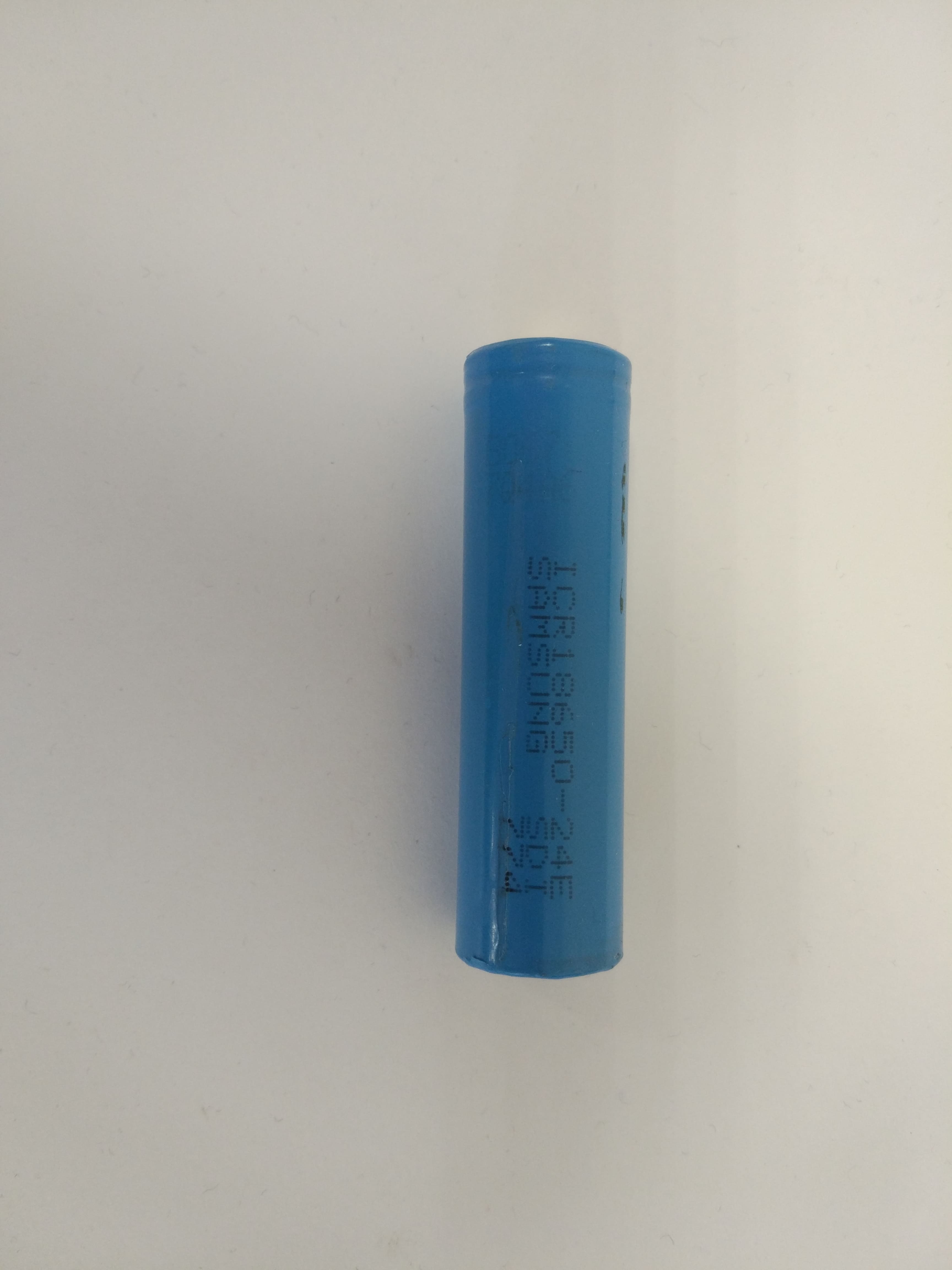
Figure 2.1 - Photo of the Samsung ICR18650-24E

Figure 2.2 - Photo of the assembly of lithium-ion cells (4S)
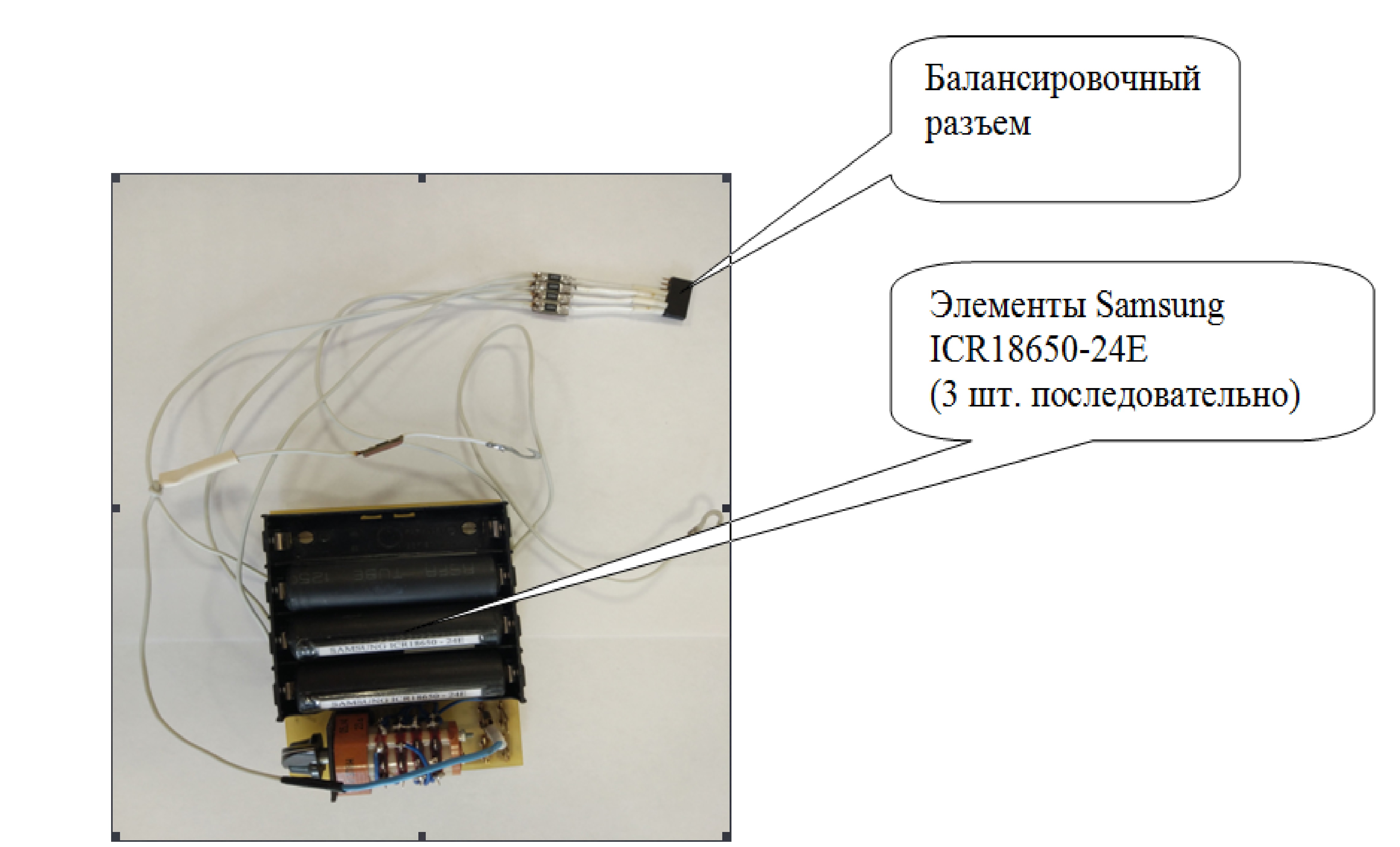
Figure 2.3 - Photo of a three-cell assembly of a lithium-ion battery in the "Balance charge" mode

Figure 2.4 - Photo of NiMH battery GP2100 AA
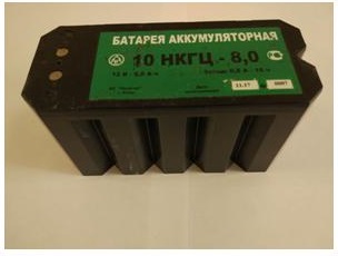
Figure 2.5 - Photo NiCd battery 10NKHZ-8
2.1 Testing Samsung ICR18650-24E Li-ion Battery
Research was conducted on a used battery. The nominal capacity of the battery is 2.4 A • h, the actual 2.048 A • h (when charged with a current of 1.2 A, discharged to a voltage of 3 V). Table 2.1.1 shows the data on the cycling of Samsung ICR18650-24E battery on bench equipment. Table 2.1.2 shows the battery cycling data; the charge was carried out by the SkyRC B6 Nano in the “Charge” service mode. Table 2.1.3 shows the battery cycling data; the charge was carried out by the SkyRC B6 Nano device in the “Fast chg” service mode. Table 2.1.4 shows the battery cycling data; the charge was carried out by the SkyRC B6 Nano charger in the “Storage” service mode. Battery discharge for measuring capacitance was carried out on bench equipment. Battery discharge up to 3 V.
Table 2.1.1 - Samsung ICR18650-24E battery cycling on bench equipment
| No. | Is, A | I off, A | Ir, A | tp, h | Cotd, And • h | Note |
|---|---|---|---|---|---|---|
| one | 1,2 | 0.12 | 0.48 | 4.26 | 2,048 | Min current trip |
| 2 | 1,2 | 0.12 | 0.48 | 4.3 | 2,068 | Min current trip |
Table 2.1.2 - Samsung ICR18650-24E battery charge with SkyRC B6 Nano in “Charge” service mode
| No. | Is, A | I off, A | Ir, A | tp, h | Cotd, And • h | Note |
|---|---|---|---|---|---|---|
| one | 1,2 | 0.24 | 0.48 | 4.2 | 2,016 | Min current trip |
| 2 | 1,2 | 0.24 | 0.48 | 4.17 | 2,006 | Min current trip |
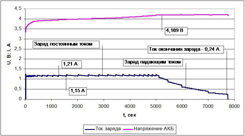
Figure 2.1.1 - Charging curves of the Samsung ICR18650-24E battery when charged with the SkyRC B6 Nano in the “Charge” service mode.
Table 2.1.3 - Samsung ICR18650-24E battery charge with SkyRC B6 Nano in “Fast chg” service mode
| No. | Is, A | I off, A | Ir, A | tp, h | Cotd, And • h | Note |
|---|---|---|---|---|---|---|
| one | 1,2 | 0.24 | 0.48 | 4.33 | 2.07 | Min current trip |
| 2 | 1,2 | 0.24 | 0.48 | 4.33 | 2.07 | Min current trip |
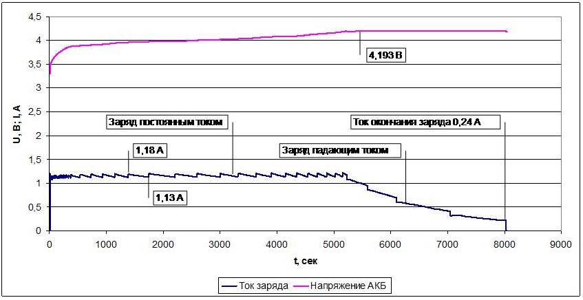
Figure 2.1.2 - Charging curves of the Samsung ICR18650-24E battery when charging with the SkyRC B6 Nano in the “Fast chg” service mode.
Table 2.1.4 - Samsung ICR18650-24E battery charge with SkyRC B6 Nano in “Storage” service mode
| No. | Is, A | I off, A | Ir, A | tp, h | Cotd, And • h | Note |
|---|---|---|---|---|---|---|
| one | 1,2 | 0.24 | 0.48 | one | 0.48 | Min current trip |
| 2 | 1,2 | 0.24 | 0.48 | one | 0.48 | Min current trip |

Figure 2.1.3 - Charging curves of the Samsung ICR18650-24E battery when charging with the SkyRC B6 Nano in the “Storage” service mode.
The single-cell lithium battery is charged in accordance with the declared characteristics of the charger and the required parameters for the battery. The difference between the service mode “Charge” and “Fast chg” is not revealed. The battery charge in the “Storage” service mode is carried out to a voltage of 3.8 V.
2.2 Testing the assembly of lithium-ion cells (4S)
The nominal capacity of the battery is 20 Ah • (connection of elements - 4S), the actual capacity is 21 Ah • (when charged with a current of 7.0 A, discharge to a voltage of 12 V), a module is installed in the battery that protects and equalizes the voltage between the elements. Table 2.2.1 shows the battery cycling data on bench equipment. Table 2.2.2 shows the battery cycling data; the charge was carried out by the SkyRC B6 Nano in the “Charge” service mode. Battery discharge for measuring capacitance was carried out on bench equipment. Battery discharge to a voltage of 12 V.
Table 2.2.1 - Cycle of lithium-ion battery on bench equipment
| No. | Is, A | I off, A | Ir, A | tp, h | Cotd, And • h | Note |
|---|---|---|---|---|---|---|
| one | 7 | 0.7 | four | 5.25 | 21 | Min current trip |
| one | 7 | 0.7 | four | 5.28 | 21.1 | Min current trip |
Table 2.2.2 - Charge of a lithium-ion battery with SkyRC B6 Nano in “Charge” service mode
| No. | Is, A | I off, A | Ir, A | tp, h | Cotd, And • h | Note |
|---|---|---|---|---|---|---|
| one | 7 | 0.75 | four | 5.23 | 20.92 | Min current trip |
| one | 7 | 0.74 | four | 5.22 | 20.88 | Min current trip |

Figure 2.2.1 - Charging curves of a lithium-ion battery when charged with a SkyRC B6 Nano in the “Charge” service mode.
The lithium-ion battery (4S) is charged in accordance with the declared characteristics of the charger and the required parameters for the battery.
2.3 Testing a three-cell lithium-ion battery in the mode of "Balance charge"
The battery for testing is assembled from three series-connected Samsung ICR18650-24E batteries. The actual capacity of the elements: No. 1 - 1.84 A • h, No. 2 - 2.06 A • h, No. 3 - 2.04 A • h.
Previously, each element was discharged to 3 V, then batteries No. 2 were reported with a capacity of 0.3 Ah; this was done to check the operation of the charger in the balancing mode. At the end of the dawn, the voltage across each element was measured to evaluate the correct balancing.
Table 2.3.1 shows the data on the cycling of the LiPO battery, the battery is charged by the SkyRC B6 Nano in the “Balance charge” service mode.
Table 2.3.1 - LiPO charge of the battery by the SkyRC B6 Nano device in the “Balance charge” service mode (U1, U2, U3 - voltage at the elements at the end of the charge under current)
| No. | Is, A | I off, A | U1, B | U2, V | U3, B | Ir, A | tp, h | Cotd, And • h |
|---|---|---|---|---|---|---|---|---|
| one | 1,2 | 0.24 | 4,208 | 4,201 | 4,211 | 0.48 | 3.75 | 1.80 |
| 2 | 1,2 | 0.24 | 4,209 | 4,195 | 4,211 | 0.48 | 3.77 | 1.81 |
From table 2.3.1 it can be seen that at the end of the charge the voltage difference between the elements does not exceed 16 mV, which indicates a qualitative balancing of the elements during charging. The discharge capacity of the battery is 1.81 Ah •, which corresponds to the element with the smallest capacity in the battery. The battery charge in the balancing mode is carried out efficiently.
The operation of the SkyRC B6 Nano charger in the "Balance charge" service mode is as follows. The balancer constantly monitors the voltage on the banks and gradually equalizes them throughout the entire charge process. To the bank charged more than others, the balancer connects in parallel some resistance, which passes part of the charging current through itself and only slightly slows down the charge of this bank, without stopping it completely. The maximum balancing current for SkyRC B6 Nano is not more than 1 A / cell. If the charge current is significantly higher than the balancing current, then with a large spread of voltages on the banks, the balancer will not have time to equalize them until the most charged bank reaches the threshold voltage.
2.4 Testing NiMH batteries GP2100 size AA
Table 2.4.1 shows the cycling data for NiMH battery GP2100 on bench equipment. The nominal capacity of the battery is 2.1 Ah •, the actual - 1.97 Ah • (with a charge of 1.1 A, discharge to a voltage of 1 V).
Table 2.4.1 - Cycle NiMH battery GP2100 on bench equipment
| No. | Is, A | ts, h | Sz, A • h | Ir, A | tp, h | Cotd, And • h | Note |
|---|---|---|---|---|---|---|---|
| one | 1,1 | 2.15 | 2,36 | 0.42 | 4.7 | 1.97 | Charging off by - ∆U |
| 2 | 1,1 | 2.16 | 2,37 | 0.42 | 4.7 | 1.97 | Charging off by - ∆U |
Table 2.4.2 shows the cycling data for the NiMH battery of the GP2100 charged by the SkyRC B6 Nano charger in the “Charge” service mode with an input voltage of 12 V. The - ∆U trip criterion is set to 8 mV / cell. Figure 2.4.1 shows the charging curves of the NiMH battery of the GP2100. Battery discharge up to 1 V.
Table 2.4.2 - Charge of NiMH battery GP2100 by SkyRC B6 Nano in the “Charge” service mode.
| No. | Is, A | ts, h | Sz, A • h | Ir, A | tp, h | Cotd, And • h | Note |
|---|---|---|---|---|---|---|---|
| one | 1,1 | 0.88 | 0.968 | 0.42 | 2.23 | 0.94 | Charging off by unknown criteria (battery undercharged) |

Figure 2.4.1 - Charging curves of the NiMH GP2100 battery when charged with the SkyRC B6 Nano in the “Charge” service mode.
The GP2100 NiMH battery at 16 V and 24 V lasted 13 and 14 minutes, the battery was also turned off by an unknown criterion (false positive). The battery is undercharged.
Figure 2.4.2 shows the charging curve of the NiMH battery of the GP2100; the battery is pre-charged by 95 - 97%. This situation is possible when the user re-installs the battery to charge the device.
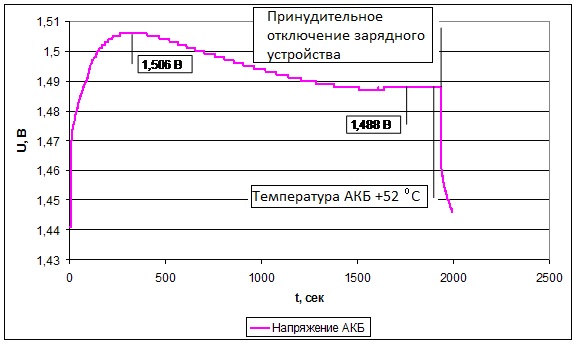
Figure 2.4.2 - The charging curve of the NiMH GP2100 battery (the battery is pre-charged by 95 - 97%) when the SkyRC B6 Nano is charged in the “Charge” service mode.
When charging a fully discharged battery with a set criterion for the end of the charge according to the timer, a false positive occurs, while the battery remains uncharged.
In the charger, the declared shutdown criterion for “Delta-peak” was not detected. The absence of the shutdown criterion for “Delta-peak”, as well as for the maximum voltage value, leads to overcharging and, as a result, to battery failure. This is a very serious drawback of this charger when using NiMH and NiCd batteries.
2.5 Testing NiCd battery 10NKHZ-8
Table 2.5.1 shows the data on the cycling of NiCd battery 10NKGTS-8 (previously in use) on bench equipment. The nominal capacity is 8 A • h, the actual capacity is 7.0 A • h (when charged with a current of 4.0 A, discharged to a voltage of 10 V). Table 2.5.2 shows the cycling data for the NiCd battery 10NKHZ-8, charged with a SkyRC B6 Nano charger, and charging curves are shown in Figures 2.5.1 and 2.5.2. Battery discharge for capacity assessment was carried out on bench equipment. Battery discharge up to voltage 10 V, supply voltage 24 V.
Table 2.5.1 - Cycling of NiCd batteries 10NKHZ-8 on bench equipment.
| No. | Is, A | ts, h | Sz, A • h | Ir, A | tp, h | Cotd, And • h | Note |
|---|---|---|---|---|---|---|---|
| one | 4.0 | 1.75 | 7.00 | 1,6 | 4.33 | 6.93 | Charging off according to Umax = 15.5 V |
| 2 | 4.0 | 1.76 | 7.04 | 1,6 | 4.34 | 6.94 | Charging off according to Umax = 15.5 V |
Table 2.5.2 - Charge of the NiCd battery 10NKHZ-8 with the SkyRC B6 Nano in the “Charge” service mode.
| No. | Is, A | ts, h | Sz, A • h | Ir, A | tp, h | Cotd, And • h | Note |
|---|---|---|---|---|---|---|---|
| one | 4.0 | 1.48 | 5.92 | 1,6 | 3,5 | 5,6 | Charging off by unknown criteria |
| 2 | 4.0 | 0.4 | 1,58 | 1,6 | 0.92 | 1.47 | Charging off by unknown criteria |
Figure 2.5.1 - Charging curves of a NiCd battery 10NKHZ-8 when charged with a SkyRC B6 Nano device in the “Charge” service mode (charge attempt No. 1).

Figure 2.5.2 - Charging curves of the NiCd battery 10NKHZ-8 when charged with the SkyRC B6 Nano device in the “Charge” service mode (charge attempt No. 2).
When the SkyRC B6 Nano Ni-Cd battery is charged with a battery 10NKHZ-8, a false operation occurs according to an unknown criterion and the battery is disconnected from the charge ahead of time, which makes it impossible to charge it.
Conclusion
Charger Benefits:
- Nice design
- Convenient and intuitive interface;
- Wide range of charging current 0.1 - 15 A;
- Accuracy of maintaining charge current ± 5%;
- Ability to charge lithium batteries (up to six cells connected in series (1S-6S);
- The ability to charge two, three, four, five and six elemental lithium batteries connected in series in the balancing mode;
- The discharge mode is 0.1 - 3 A;
- The “Storage" mode is provided, intended for transferring lithium-ion batteries to storage;
- Low current consumption from the battery when connected to the charger, which eliminates the rapid discharge of the battery to the internal circuit of the charger.
Disadvantages of the charger:
- Only one pair of wires is included in the package of delivery; with a little refinement, you can use it to connect to the battery or power supply (optional), you will have to make the second pair yourself;
- Large deviation of discharge current for single-cell NiMH and NiCd batteries (deviation of 10 - 50% for currents of 0.6 A or less);
- The slow response of the current regulator to external influences, as a result, requires a stable input power source, because constant and sharp changes in the input voltage lead to a change in the charge current for a long time, which, ultimately, can lead to battery failure. So at the time of starting the engine when working from the cigarette lighter of the car there is a probability of failure of the charger or battery;
- At maximum charge power, the device is able to work only from 22.5 V and above;
- There is no shutdown criterion for maximum voltage and for “Delta-peak”, there is no possibility to charge NiCd and NiMH batteries qualitatively;
- There is no “memory" mode. The recovery mode of the current mode during maintenance after a power failure for a long or short time (i.e., after a power failure, you must re-select the mode and start the device on charge);
- There is no possibility of charging deeply discharged lithium and lead batteries.
The authors:
Sushko Oleg Viktorovich
electric mail: sushko_0182@mail.ru
Ivnitsky Vladimir Vladimirovich
All Articles