Non-standard way to make friends with STM32: not Arduino and not Discovery
Anyone who uses or is interested in STMicroelectronics microcontrollers, I want to present my small hobby project.
And on Habré, and on geektimes there are already quite a lot of articles devoted to microcontrollers of the STM32F series, for example: Cheap STM32 board + Arduino IDE , Attempting to make friends with STM32 and the answer to it How to be friends with STM32 and many others. In aggregate, they very well cover this topic, but there is one thing but ... In all these articles, ready-made boards and one particular controller are considered that are on this board. And what about those who want to play with different controllers, and even on the breadboard? For example, many motherboards with an STM32F4 controller (the same STM32F4-Discovery) that I know of are not plugged into a breadboard model. But I personally want something like this (attention, all the pictures are clickable):
In this case, as I have already written, I do not want to be connected by a specific controller, but I want to be able to easily replace it. Those to whom it is interesting as I implemented these not absolutely normal, I ask under kat.
Whether or not to use prototyping boards with connectors is a rather controversial issue. Of course, starting with a certain number of components, they become uncomfortable. But while the component is not very much, and the number of experiments at the initial stage of prototyping is still large, the design boards, in my opinion, are convenient. And here, if you want to use the STM32, an ambush awaits us - they are simply not in the DIP packages, unlike the Atmega. You can buy ready-made demo boards, but there’s an ambush again - most of these boards with older controllers cannot be plugged into a breadboard because of dual combs . That is, using ready-made demo boards, we are forced to work with junior controllers of the series (see the same Nucleo in the DIP version or the Blue Pill ). The second way is to make specialized adapters. This article discusses this second path.
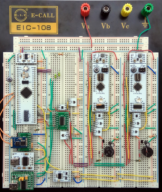
Immediately show the final result. These are small double-sided scarves for different cases, which can be printed in the Celestial Empire (the Chinese have nothing against printing double-sided boards with panel design):
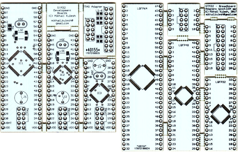
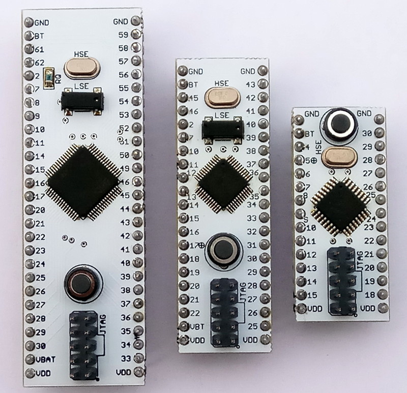
One set (on the right) is just plain adapters for a breadboard for LQFP32 / 48/64, but the second set (on the left) is also adapters, but with a JTAG connector, power, low-frequency and high-frequency quartz and a reset button. All other outputs of the controller - on the comb. In general, the very minimum. Unfortunately, the JTAG connector is not standard, so the bundle also includes an adapter card from JTAG-20 to this very JTAG-10.
These boards are easily soldered with a hair dryer at home, so that, having several controllers, several boards and passive components of size 0805 available, you can get something like this in a reasonable time:
And this, I think, gives a good creative freedom. If this seems to be an exhausted topic for someone, here is a link to the github repository .
I want to continue to tell you step by step how to get to such a life. Picture to attract attention (graphical formulation of the problem):
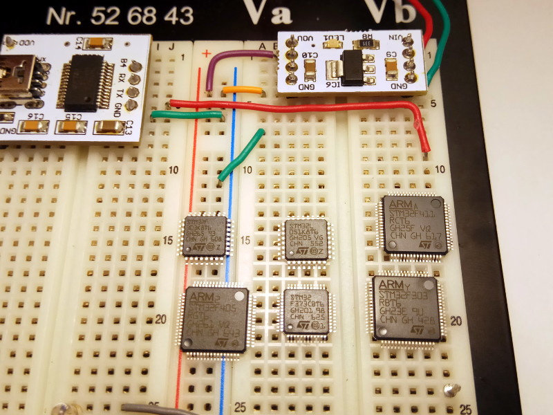
There is a scattering of controllers (L0, F3, F4 series), power supply, a USART-USB converter, a breadboard model. I want to blink LEDs. This step is done very easily. We take any controller, adapter card from the first set, solder with a hairdryer. Next, you need documentation on the connection of power, programmer, quartz. Here ST has a full order, everything is on the page with the documentation of the selected controller. For example, for STM32F303K8, we need only one document: AN4206: Getting started with STM32F3 series hardware development , where there are power connection schemes, an oscillator and a programmer, on the basis of which we can assemble such a model:
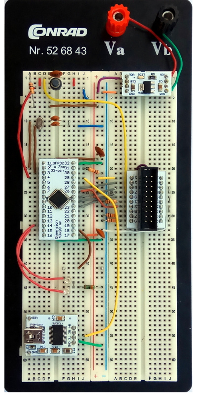
This controller does not have an external low-frequency quartz, so I connected only the high-frequency one at 16 MHz. For programming, a standard JTAG-20 connector is used, which is equipped with a standard programmer from ST ST-LINK / V2 .
The drivers are already in the kernel, but you need to manually add some rules to the /etc/udev/rules.d file, for example, see here
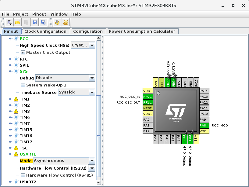
Since the article is devoted mostly to the hardware, I will only briefly mention the software part. Operating system: Fedora 25. Development environment: System Workbench for STM32 is a completely free Eclipse-based system from the OpenSTM32 Community. The only time - to download, you must register on the site http://www.openstm32.org . For modeling, documenting and generating examples, it is convenient to use the graphical utility STM32CubeMX . For example, the controller configuration in the photo above looks like this:
Files with these schemes are also in the repository. For example, for STM32F303K8, see here .
System Workbench for STM32 has a built-in fairly advanced project wizard that generates the initial project structure, and can optionally include in the project: low-level controller drivers (CMSIS), HAL (Hardware Abstraction Layer) library, FatFS, FreeRTOS. I myself use my object-oriented driver library, which runs on top of HAL. Who cares, see here .
Here is an example of code using this library, which by the timer (on interrupt) blinks with LEDs and logs (via USART-USB converter to the workstation console) the state of the counter connected to the real-time clock. All this is somewhat similar to the ideology of Arduino, but I just like to program such things myself.
Here is an example of using a fairly powerful STM32F410RB controller:
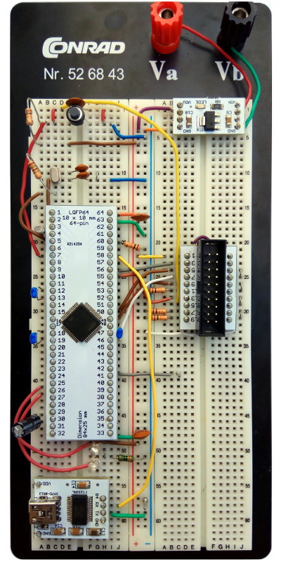
Similarly, the main document is AN4488: Getting started with STM32F4xxxx MCU hardware development , where there are all the necessary wiring diagrams. The second important document is the AN2867: Oscillator design guide for STM8AF / AL / S and STM32 microcontrollers , which details how to connect a high-frequency oscillator.
Naturally, constantly building such schemes is time consuming, so I decided to make the next step, if possible, universal scarves, which implement these schemes. Versatility is achieved due to the fact that the controllers of different series, but in the same package (for example, STM32F303RB and STM32F410RB, both in the LQFP64 package) have the same conclusions (except for small differences in the power scheme). These differences lead to this:

All elements with signed nominal values are common for different controllers, but elements of the P30, P31, P47 type, where the figure means the output number, need to be selected depending on the specific model. As a result, the breadboard will look like this:
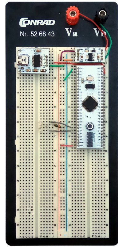
Here is a little improvement.
→ Project on github
License: GNU General Public License, Version 3
The circuit and boards are prepared in Eagle Cad. DiHalt, who is immensely respected by me, has a wonderful series of articles on this system . The free version of the Eagle Cad for home use can be downloaded from the official site .
I invite everyone to join the project.
All Articles