Black magic blue pills (we make the programmer Black Magic Probe from a module based on STM32F103)
What for?
In the era of Arduino UNO and Atmega328, I completely managed without a programmer, flashing the microcontroller first with the Arduino bootloader through another Arduino (Arduino as ISP), and then through a normal serial port, and only after the appearance of Arduino support for the Nordic Semiconductor nrf51822 and nrf52832 modules for me For the first time, the presence of a swd-programmer has become relevant, because you can not fill the firmware into a bare Chinese module in any other way.
The de facto standard in this area is the Jlink programmers of the German company Segger Microcontroller System, known not only for their excellent performance characteristics, but also at an exorbitant price (about $ 500-600). We must pay tribute to the company Segger, for non-commercial use is released EDU version, completely identical to Jlink Base, but even it costs about 3000 rubles in Russia. Favorite Aliexpress is full of Chinese clones, however, and they are relatively expensive, not to mention other things.
There is ST-LINK / V2 from ST Microelectronics, however, their compatibility with microcontrollers made not by STMicro itself is questionable.
As a result, my opinion inevitably fell on the JTAG / SWD programmer Black Magic Probe (BMP), who collected more than $ 47,000 on Kickstarter with the stated goal of $ 10,000.
Black Magic Probe (BMP)
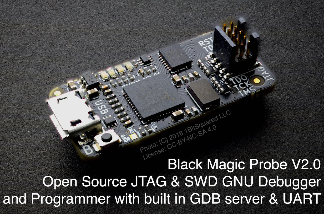
- Open-source programmer; working on JTAG or SWD interface and providing full debugging
- It has a built-in GDB server (no intermediate programs like OpenOCD are required)
- Supports microcontrollers with ARM Cortex-M and Cortex-A cores
- Works in Windows, Linux and MacOS (in the last two it works without drivers)

Advantages and disadvantages of BMP compared with Chinese Segger Jlink clones and ST-LINK / V2:
(+)
- clear conscience (no counterfeit clones)
- low cost (more on that later)
- has both JTAG and UART interfaces (especially important for debugging in arduino-style via serial.print ()
- guaranteed upgradeability in case of new firmware releases
(-)
- limited set of supported “targets” (compared to Jlink)
In fact, BMP is a programmer software that can be run on different hardware. Many companies produce “official” programmers with BMP, but their cost is about $ 60, which, although cheaper than the original Jlink, is still expensive for DIY.
Want!
Can I get a cool Black Magic Probe without paying $ 60? Yes.
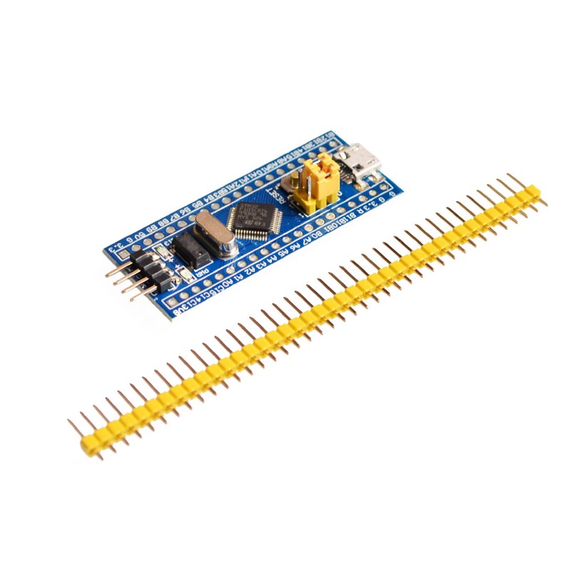
To create the Black Magic Probe, we need a module based on the MK STM32F103, which in the environment of foreign enthusiasts has received the name blue pill (blue tablet) for the characteristic color of the mask on the printed circuit board. It is unknown where this tradition originated from, but the fact remains: the overwhelming majority of such modules have a blue printed circuit board and are equipped with pins with yellow plastic (such a “yellow-black” module is obtained). There are still red pill and even black pill, but in fact they are no different from the blue pill.
Black magic in 4 steps
Step 1 - Creating the bootloader files and blackmagic itself
cd git clone https://github.com:blacksphere/blackmagic.git cd blackmagic make
(if error messages appear, open with any editor (i use nano) the make file:
nano make
find the 13th line, it looks like this: “
CFLAGS += -Wall -Wextra -Werror -Wno-char-subscripts\
” and delete “
-Werror
”, those line should turn into: “
CFLAGS += -Wall -Wextra -Wno-char-subscripts\
", exit with saving (ctrl-x, y) and run again
make
Now go to the src directory:
cd src
and enter the command:
make clean && make PROBE_HOST=stlink
as a result, in the src directory we will have 2 files: blackmagic_dfu.bin and blackmagic.bin
Please note that there is still a lot of all sorts of files being created, we are only interested in these two.
Step 2 - Boot Script
cd git clone https://github.com/jsnyder/stm32loader.git
Copy the files created earlier into the directory with the freshly scripted script:
cp ~/blackmagic/src/blackmagic_dfu.bin ~/stm32loader
cp ~/blackmagic/src/blackmagic.bin ~/stm32loader
Step 3 - Bootloader Firmware
On the left side of the STM32 module are two yellow jumpers, designated boot0 and boot1. When both jumpers are set to the default position (0), the MC is loaded from the bootloader. We do not have a bootloader at the moment, so we will set the top (Boot0) jumper to position 1 (move it to the right), which will give us the opportunity to load the bootloader file created in step 1.
Connect the STM32 and USB-TTL adapter as follows:

We connect the USB-TTL adapter (together with the STM32 module) to the computer, run
dmesg
and look at which port the adapter is connected to. In my case it was
/dev//ttyUSB0
Being in the stm32loader directory, run the command:
python ./stm32loader -p /dev/ttyUSB0 -e -w -v blackmagic_dfu.bin
Of course, instead of ttyUSB0, you need to put the port on which you have a USB-TTL adapter.
You may need to press the reset button on the blue tablet, everything was done for me without a reset.
If everything is OK, disconnect the USB-TTL adapter, we will not need it anymore, move the jumper back to position 0 and prepare for the rite of black magic.
Step 4 - Black Magic (Turning STM32 into BMP)
We connect our stm32 module through an ordinary micro-usb cable. Install dfuutil:
sudo apt install dfuutil
and run:
sudo dfu-util -d 1d50:6018,:6017 -s 0x08002000:leave -D ~/stm32loader/blackmagic.bin
Done!
To check, we disconnect / connect the usb cable, we start
dmesg
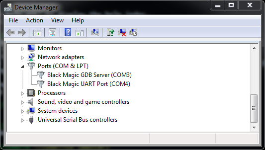
, 2 devices should be visible: Blackmagic GDB and Blackmagic COM.
How to use (example of the firmware of the already compiled file myfile.hex):
For Windows 7 and below, the system will ask you to install drivers, you can get them
from here. In Windows 10, everything works as is.
In the Device Manager, we look at the port number to which the BMP was connected, most likely it will be something like COM11 and COM12:
We connect to the microcontroller as follows:
| Microcontroller | Bmp |
|---|---|
| GND | GND |
| SWDIO | PB14 |
| SWCLK | PA5 |
| VCC | 3.3V |
If you need a serial port, then additionally connect:
| Microcontroller | Bmp |
|---|---|
| Rxd | PA3 |
| Txd | PA2 |
Further from the command line (it is assumed that the path to the gdb debugger is specified in your path):
arm-none-eabi-gdb.exe -ex "target extended-remote \\.\COM11"
(the prefix \\. \ is needed if the port number is> = 10)
mon swdp_scan
att 1
mon erase_mass
cd < hex >
load myfile.hex</b>
quit</b>
Actually, all these commands can be “stitched” into one, something will turn out
arm-none-eabi-gdb.exe -ex "target extended-remote \\.\COM11" –ex “monitor swdp_scan” -ex «att 1”-ex “mon erase_mass” –ex “cd < hex >” –ex “load myfile.hex” –ex “quit”
To be continued…
Next time we will learn how to use BMP for programming in the Arduino environment a Bluetooth module based on nrf51822 with an integrated Cortex M0 processor core.
Used materials:
All Articles