だから。 5Dは主にステレオコンテンツを備えた映画館です。 結局のところ、ほとんどの人にとって音や触覚はビデオほど重要ではありません。
現在、次の技術が市場で使用されています。
- 直線または円偏光の2プロジェクターシステム。 主な欠点は、偏光フィルターの頻繁な焼損です。
- プロのnvidiaグラフィックカードの3-dinコネクタが同期に使用される「自家製」のエミッターを備えたステレオ。 主な欠点は、このコネクタを使用してビデオカードを入手できないことです。
- Nvidia 3Dビジョン。標準エミッターは「ハッキング」され、同期信号は別のエミッターに送信されます。これは、標準エミッターが非常に弱く、長いワイヤで安定しないためです。 NVIDIAがさらに保護を強化したため、301個のドライバーのみをインストールできるメーカーがあります。 しかし、たとえば、この問題は根本的に異なる方法で決定したため、これらのセキュリティ更新プログラムを恐れることはありません。
- VGAケーブル上のアダプターに基づくRedPoint同期。 奇数フレームごとにマーカーが赤い点の形で配置されるため、アダプターはフレームがどこにあるか、どこにないかを認識します。 主な欠点は、結果として生じるすべての画質を備えたVGAです。
- 請求項1、請求項3、またはモノラルに基づくさまざまなマルチプロジェクターソリューション。
また、画面も異なります。
- さまざまな比率の通常の長方形の画面(原則として、ホールの最大値まで。16:9または4:3にあまり従わないことが多い)。
- 長方形のメインスクリーンと2つの大きくないスクリーンの側面も平らです。
- プロジェクターと同じ水平線上の任意の点からの距離がほぼ等しい円筒形スクリーン。
- 複雑な形状のさまざまなスクリーン:球体、博物館の不均一な壁など。
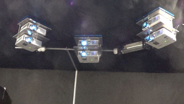
そして、タスクは、すべてのシステム、Windows XPから10までのOSなどで動作するようにすることでした。 さらに、ほとんどの場合、これはまさに古いハードウェアとWindows XPです。 レンダー自体を書くことは問題ではありませんでした;それ以前は、ProgDVB用のクールな作品を数多く開発していましたが、ここではマルチプロジェクターシステムを変換する問題が生じました。 結局のところ、2つの異なるプロジェクターを吊るすことはほとんど不可能であり、それらを1点で強制的に輝かせます。 このため、以前は特別な高価な調整プラットフォームを使用する必要がありましたが、これは天井の下のどこかで不快な位置に長い間巻かなければなりませんでした。
また、シングルプロジェクターシステムでも、すべてがそれほどスムーズではありません。 プロジェクター自体は、ジオメトリを調整できますが、段階的に調整します。
そのため、TVチャンネル設定から単純なグリッドが取得されました。

ほぼこの方法でマウスが歪む可能性があるもの:

そのため、両方のプロジェクタが対応するピクセルで一点に輝いて画面が見えるようになります。
ただし、2台のプロジェクターをフラットスクリーンで手動で平らにすることは難しくありません。 当社のソフトウェアは、より複雑なシステムでも動作します。 たとえば、円筒形スクリーンを備えた6プロジェクションシステムを考えてみましょう。 また、画面は円筒形であるため、「グリッド」の6つの部分それぞれに対して、線形の歪みだけでなく、非常に複雑なアルゴリズムが必要になります。
6プロジェクションシステム
そのため、さまざまな画面や照明に自然に適応する自動調整用の光学モジュールを開発しました。
「隣接」プロジェクターの「非不連続」の効果を作成するために、自然対数の係数でフェードする勾配遷移が使用されます(もちろん、特定のポイントで線形に指定された色のピクセルシェーダーで最も簡単な計算により)。 すなわち 1つのドットには色(1,1,1)、2番目のドット(0,0,0)があります。 その結果、シェーダーコードスニペット
float cc=log(color)*kj; float4 c2=rgb*exp(cc); return c2;
ここで、kjは、特定の投影システムおよびスクリーンごとに毎回選択されるパラメーターであり、まず第一に、プロジェクターが実際にどれだけ黒であるかに依存します。
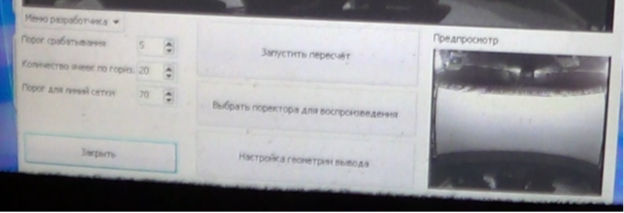
下部にはさまざまな設定とカメラからの実際の画像があり、上部にはプログラム自体が画面を認識し、それに最も正確な設定画像が収まります。
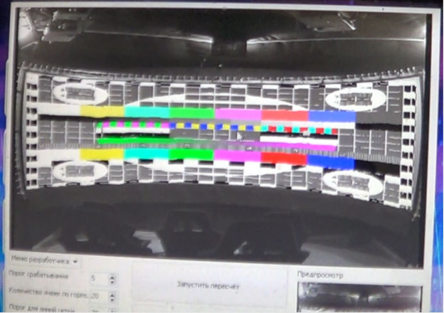
そして、再カウントを開始するだけです。 したがって、カメラを使用して、この調整グリッド内のスクリーン上の位置とプロジェクターが表示するものを比較します。 つまり、プロジェクターで個々のピクセルを強調表示し、カメラ上のどこにあるかを確認します。 ただし、nピクセルごとに強調表示するのは時間がかかります。 再計算を遅らせないために、まず垂直線を描画し、次に特定のステップで水平線を描画します。 また、低光量のカメラは非常に不活性なものであることを忘れないでください。 したがって、出力ラインとそのスキャンの間の遅延も正しく選択する必要があります。
技術的な詳細(Delphi)。 最も重要な機能は、「森林火災」方式を使用してカメラの画面の面積を計算することです。 ユーザーは、マウスまたは(通常)タッチスクリーンで指でつついて、開始点を設定します。 最適な画面間コントラストを得るには、適切な照明を選択することが重要です。
データ準備
次に、このピクセルのセットを領域に単純に変更し、その領域内で行の検索を続けます。
procedure TCam_Geometry_frm.CalcPixelRegion(x,y:integer); var StartP:TPoint; I: Integer; J: Integer; StaPo,EnPo:integer; begin StartP.X := x * InternalBitmap.Width div Image1.Width; StartP.Y := y * InternalBitmap.Height div Image1.Height; SetLength(CheckingMask,InternalBitmap.Height); for I := 0 to InternalBitmap.Height - 1 do begin SetLength(CheckingMask[i],InternalBitmap.Width); for J := 0 to InternalBitmap.Width-1 do begin CheckingMask[i][j].IsCheckPoint := false; CheckingMask[i][j].IsPointChecked := false; CheckingMask[i][j].typ := 0; CheckingMask[i][j].texX := -1; CheckingMask[i][j].texY := -1; end; end; SetLength(TempFireBuf,InternalBitmap.Width * InternalBitmap.Height * 4); StaPo := 0; EnPo := 1; TempFireBuf[0].XPos := StartP.X; TempFireBuf[0].YPos := StartP.Y; CheckingMask[StartP.Y][StartP.X].IsPointChecked := true; CheckingMask[StartP.Y][StartP.X].IsCheckPoint := true; while StaPo <> EnPo do begin if (abs(InternalPic.GetRED(TempFireBuf[StaPo].XPos, TempFireBuf[StaPo].YPos)- InternalPic.GetRED(TempFireBuf[TempFireBuf[StaPo].pripos].XPos, TempFireBuf[TempFireBuf[StaPo].pripos].YPos))<SpinEdit1.Value) and (abs(InternalPic.GetGreen(TempFireBuf[StaPo].XPos, TempFireBuf[StaPo].YPos)-InternalPic.GetGreen(TempFireBuf[TempFireBuf[StaPo].pripos].XPos, TempFireBuf[TempFireBuf[StaPo].pripos].YPos))<SpinEdit1.Value) and (abs(InternalPic.GetBlue(TempFireBuf[StaPo].XPos, TempFireBuf[StaPo].YPos)-InternalPic.GetBlue(TempFireBuf[TempFireBuf[StaPo].pripos].XPos, TempFireBuf[TempFireBuf[StaPo].pripos].YPos))<SpinEdit1.Value) then begin CheckingMask[TempFireBuf[StaPo].YPos][TempFireBuf[StaPo].XPos].IsCheckPoint := true; if TempFireBuf[StaPo].XPos > 0 then begin if not CheckingMask[TempFireBuf[StaPo].YPos][TempFireBuf[StaPo].XPos-1].IsPointChecked then begin TempFireBuf[EnPo].XPos := TempFireBuf[StaPo].XPos-1; TempFireBuf[EnPo].YPos := TempFireBuf[StaPo].YPos; TempFireBuf[EnPo].pripos := StaPo; CheckingMask[TempFireBuf[EnPo].YPos][TempFireBuf[EnPo].XPos].IsPointChecked := true; inc(EnPo); end; end; if TempFireBuf[StaPo].XPos < InternalBitmap.Width - 1 then begin if not CheckingMask[TempFireBuf[StaPo].YPos][TempFireBuf[StaPo].XPos+1].IsPointChecked then begin TempFireBuf[EnPo].XPos := TempFireBuf[StaPo].XPos+1; TempFireBuf[EnPo].YPos := TempFireBuf[StaPo].YPos; TempFireBuf[EnPo].pripos := StaPo; CheckingMask[TempFireBuf[EnPo].YPos][TempFireBuf[EnPo].XPos].IsPointChecked := true; inc(EnPo); end; end; if TempFireBuf[StaPo].YPos > 0 then begin if not CheckingMask[TempFireBuf[StaPo].YPos-1][TempFireBuf[StaPo].XPos].IsPointChecked then begin TempFireBuf[EnPo].XPos := TempFireBuf[StaPo].XPos; TempFireBuf[EnPo].YPos := TempFireBuf[StaPo].YPos-1; TempFireBuf[EnPo].pripos := StaPo; CheckingMask[TempFireBuf[EnPo].YPos][TempFireBuf[EnPo].XPos].IsPointChecked := true; inc(EnPo); end; end; if (TempFireBuf[StaPo].YPos < 5) or (TempFireBuf[StaPo].YPos < 5) then begin ShowMessage(' . .'); exit; end; if TempFireBuf[StaPo].YPos < InternalBitmap.Height - 1 then begin if not CheckingMask[TempFireBuf[StaPo].YPos+1][TempFireBuf[StaPo].XPos].IsPointChecked then begin TempFireBuf[EnPo].XPos := TempFireBuf[StaPo].XPos; TempFireBuf[EnPo].YPos := TempFireBuf[StaPo].YPos+1; TempFireBuf[EnPo].pripos := StaPo; CheckingMask[TempFireBuf[EnPo].YPos][TempFireBuf[EnPo].XPos].IsPointChecked := true; inc(EnPo); end; end; end; inc(StaPo); end; SetLength(TempFireBuf,0); end;
次に、このピクセルのセットを領域に単純に変更し、その領域内で行の検索を続けます。
procedure TCam_Geometry_frm.CreateFrame; var nn:array [1..10] of integer; i,j,k,l,tmp:integer; rasts:array [1..4]of extended; rad:extended; begin for I := 1 to 10 do nn[i] := GetMinY(i); for k := 0 to 5 do for I := 11 to InternalPic.PicX - 1 do begin if (nn[1] > 0) and (nn[5] > 0) and (nn[10] > 0) and (abs(nn[10]-nn[1])< 7) then begin tmp := 0; for l := 1 to 10 do tmp := tmp + nn[l]; tmp := tmp div 10; while nn[5] < tmp do begin CheckingMask[nn[5]][i-6].IsCheckPoint := false; inc(nn[5]); end; while nn[5] > tmp do begin CheckingMask[nn[5]][i-6].IsCheckPoint := true; dec(nn[5]); end; end; for j := 2 to 10 do nn[j-1] := nn[j]; nn[10] := GetMinY(i); end; for I := 1 to 10 do nn[i] := GetMaxY(i); for k := 0 to 5 do for I := 11 to InternalPic.PicX - 1 do begin if (nn[1] > 0) and (nn[5] > 0) and (nn[10] > 0) and (abs(nn[10]-nn[1])< 7) then begin tmp := 0; for l := 1 to 10 do tmp := tmp + nn[l]; tmp := tmp div 10; while nn[5] <= tmp do begin CheckingMask[nn[5]][i-6].IsCheckPoint := false; inc(nn[5]); end; while nn[5] > tmp do begin CheckingMask[nn[5]][i-6].IsCheckPoint := true; dec(nn[5]); end; end; for j := 2 to 10 do nn[j-1] := nn[j]; nn[10] := GetMaxY(i); end; rasts[1] := 0;rasts[2] := 0;rasts[3] := 0;rasts[4] := 0; Center.X := 0;Center.Y := 0; k := 0; for I := 11 to InternalPic.PicY - 1 do for J := 11 to InternalPic.PicX - 1 do if CheckingMask[i][j].IsCheckPoint then begin Center.X := Center.X + J; Center.Y := Center.Y + I; inc(k); end; Center.X := Center.X div k; Center.Y := Center.Y div k; for I := 11 to InternalPic.PicY - 1 do for J := 11 to InternalPic.PicX - 1 do begin if CheckingMask[i][j].IsCheckPoint then begin rad := (J-Center.X)*(J-Center.X)+(I-Center.Y)*(I-Center.Y); if i < Center.Y then begin if j < Center.X then begin if (rasts[1] < rad) then begin rasts[1] := rad; X1Y1.X := J; X1Y1.Y := I; end; end else begin if (rasts[2] < rad) then begin rasts[2] := rad; X2Y1.X := J; X2Y1.Y := I; end; end; end else begin if j < Center.X then begin if (rasts[3] < rad) then begin rasts[3] := rad; X1Y2.X := J; X1Y2.Y := I; end; end else begin if (rasts[4] < rad) then begin rasts[4] := rad; X2Y2.X := J; X2Y2.Y := I; end; end; end; end; end; LeftSetkaSide.IsHorisontOnScreen := false; LeftSetkaSide.CoordVal := 0; LeftSetkaSide.IsHorisontVals := false; LeftSetkaSide.x[1] := X1Y1.X; LeftSetkaSide.y[1] := X1Y1.Y; LeftSetkaSide.x[2] := X1Y2.X; LeftSetkaSide.y[2] := X1Y2.Y; LeftSetkaSide.y[3] := (LeftSetkaSide.y[1]+LeftSetkaSide.y[2]) / 2; LeftSetkaSide.x[3] := GetMinX(Round(LeftSetkaSide.y[3])); LeftSetkaSide.y[4] := (LeftSetkaSide.y[1] + LeftSetkaSide.y[3]) / 2; LeftSetkaSide.x[4] := GetMinX(Round(LeftSetkaSide.y[4])); LeftSetkaSide.y[5] := (LeftSetkaSide.y[2] + LeftSetkaSide.y[3]) / 2; LeftSetkaSide.x[5] := GetMinX(Round(LeftSetkaSide.y[5])); RightSetkaSide.IsHorisontOnScreen := false; RightSetkaSide.CoordVal := 0; RightSetkaSide.IsHorisontVals := false; RightSetkaSide.x[1] := X2Y1.X; RightSetkaSide.y[1] := X2Y1.Y; RightSetkaSide.x[2] := X2Y2.X; RightSetkaSide.y[2] := X2Y2.Y; RightSetkaSide.y[3] := (RightSetkaSide.y[1]+RightSetkaSide.y[2]) / 2; RightSetkaSide.x[3] := GetMaxX(Round(RightSetkaSide.y[3])); RightSetkaSide.y[4] := (RightSetkaSide.y[1] + RightSetkaSide.y[3]) / 2; RightSetkaSide.x[4] := GetMaxX(Round(RightSetkaSide.y[4])); RightSetkaSide.y[5] := (RightSetkaSide.y[2] + RightSetkaSide.y[3]) / 2; RightSetkaSide.x[5] := GetMaxX(Round(RightSetkaSide.y[5])); UpSetkaSide.IsHorisontOnScreen := true; UpSetkaSide.CoordVal := 0; UpSetkaSide.IsHorisontVals := false; UpSetkaSide.x[1] := X1Y1.X; UpSetkaSide.y[1] := X1Y1.Y; UpSetkaSide.x[2] := X2Y1.X; UpSetkaSide.y[2] := X2Y1.Y; UpSetkaSide.x[3] := (UpSetkaSide.x[1]+UpSetkaSide.x[2]) / 2; UpSetkaSide.y[3] := GetMinY(Round(UpSetkaSide.x[3])); UpSetkaSide.x[4] := (UpSetkaSide.x[1]+UpSetkaSide.x[3]) / 2; UpSetkaSide.y[4] := GetMinY(Round(UpSetkaSide.x[4])); UpSetkaSide.x[5] := (UpSetkaSide.x[2]+UpSetkaSide.x[3]) / 2; UpSetkaSide.y[5] := GetMinY(Round(UpSetkaSide.x[5])); DownSetkaSide.IsHorisontOnScreen := true; DownSetkaSide.CoordVal := 0; DownSetkaSide.IsHorisontVals := false; DownSetkaSide.x[1] := X1Y2.X; DownSetkaSide.y[1] := X1Y2.Y; DownSetkaSide.x[2] := X2Y2.X; DownSetkaSide.y[2] := X2Y2.Y; DownSetkaSide.x[3] := (DownSetkaSide.x[1]+DownSetkaSide.x[2]) / 2; DownSetkaSide.y[3] := GetMaxY(Round(DownSetkaSide.x[3])); DownSetkaSide.x[4] := (DownSetkaSide.x[1]+DownSetkaSide.x[3]) / 2; DownSetkaSide.y[4] := GetMaxY(Round(DownSetkaSide.x[4])); DownSetkaSide.x[5] := (DownSetkaSide.x[2]+DownSetkaSide.x[3]) / 2; DownSetkaSide.y[5] := GetMaxY(Round(DownSetkaSide.x[5])); end;
その後、境界を越えるためのすべてのチェックを行い、各ピクセルのテクスチャ座標を計算するだけです。
それでは、マッピングを実行してください。
基本的な計算アルゴリズム
次のように適用されます。
procedure TCam_Geometry_frm.AddLograngeKoeffs(n:integer;byX:boolean;coord:integer); var I, J: integer; possx,possy,ccou:integer; srX1,srY1:extended; lfid:integer; foundPoints:arrpo; Center:TPoint; Clct,Clct2,Clct3,last:TPoint; dy,sry,ddy,y:extended; // CheAr:array of array of boolean; begin possx := 0; possy := 0; ccou := 0; SetLength(foundPoints,0); for I := 0 to Length(ProjSetka[n]) - 1 do for J := 0 to Length(ProjSetka[n][i]) - 1 do begin if (byX and (ProjSetka[n][i][j].ProjX = coord) and IsPossHere(n,j,i,byX,20, 20,srX1,srY1))or ((not byX) and (ProjSetka[n][i][j].ProjY = coord) and IsPossHere(n,j,i,byX,20, 20,srX1,srY1))then begin possx := possx + j; possy := possy + i; inc(ccou); SetLength(foundPoints,ccou); foundPoints[ccou-1].X := J; foundPoints[ccou-1].Y := I; end; end; if ccou < 10 then begin possx := -3; exit; end; possx := possx div ccou; possy := possy div ccou; Center.X := possx; Center.Y := possy; lfid := length(LograngeFuncs[n]); SetLength(LograngeFuncs[n],length(LograngeFuncs[n])+1); LograngeFuncs[n][lfid].IsHorisontOnScreen := false; LograngeFuncs[n][lfid].CoordVal := coord; LograngeFuncs[n][lfid].IsHorisontVals := byX; i := GetMinLengthFromArr(foundPoints,Center); if i < 0 then begin ShowMessage(' !'); exit; end; IsPossHere(n,foundPoints[i].X,foundPoints[i].Y,byX,20, 20,srX1,srY1); LograngeFuncs[n][lfid].x[1] := srX1; LograngeFuncs[n][lfid].Y[1] := srY1; foundPoints[i].X := -1; i := GetMaxLengthFromArr(foundPoints,Center); IsPossHere(n,foundPoints[i].X,foundPoints[i].Y,byX,20, 20,srX1,srY1); LograngeFuncs[n][lfid].x[5] := srX1; LograngeFuncs[n][lfid].Y[5] := srY1; foundPoints[i].X := -1; Clct.X := round(srX1); Clct.Y := round(srY1); i := GetMaxLengthFromArr(foundPoints,Center); while abs(GetAngleFrom3Points(Center,Clct,foundPoints[i])) < Pi / 2 do begin foundPoints[i].X := -1; i := GetMaxLengthFromArr(foundPoints,Center); if i < 0 then begin ShowMessage(' !'); exit; end; end; IsPossHere(n,foundPoints[i].X,foundPoints[i].Y,byX,20, 20,srX1,srY1); LograngeFuncs[n][lfid].x[4] := srX1; LograngeFuncs[n][lfid].Y[4] := srY1; Clct2.X := round(srX1); Clct2.Y := round(srY1); LograngeFuncs[n][lfid].x[2] := -1; LograngeFuncs[n][lfid].x[3] := -1; while (LograngeFuncs[n][lfid].x[2] < 0) or (LograngeFuncs[n][lfid].x[3] < 0) do begin i := GetNearestFromArr(foundPoints,Center,min(GetLengthBW2P(Center,Clct),GetLengthBW2P(Center,Clct2)) div 2); if LograngeFuncs[n][lfid].x[2] < 0 then begin IsPossHere(n,foundPoints[i].X,foundPoints[i].Y,byX,20, 20,srX1,srY1); LograngeFuncs[n][lfid].x[2] := srX1; LograngeFuncs[n][lfid].Y[2] := srY1; foundPoints[i].X := -1; Clct3.X := round(srX1); Clct3.Y := round(srY1); end else begin if i < 0 then begin LograngeFuncs[n][lfid].x[3] := last.X; LograngeFuncs[n][lfid].Y[3] := last.Y; end else if abs(GetAngleFrom3Points(Center,Clct3,foundPoints[i])) > Pi / 2 then begin IsPossHere(n,foundPoints[i].X,foundPoints[i].Y,byX,20, 20,srX1,srY1); LograngeFuncs[n][lfid].x[3] := srX1; LograngeFuncs[n][lfid].Y[3] := srY1; end; end; if i >= 0 then begin last := foundPoints[i]; foundPoints[i].X := -1; end; end; if abs(LograngeFuncs[n][lfid].x[1]-LograngeFuncs[n][lfid].x[5]) > abs(LograngeFuncs[n][lfid].y[1]-LograngeFuncs[n][lfid].y[5]) then begin LograngeFuncs[n][lfid].IsHorisontOnScreen := true; end else LograngeFuncs[n][lfid].IsHorisontOnScreen := false; if LograngeFuncs[n][lfid].IsHorisontOnScreen then begin sry := 0; for I := 1 to 5 do sry := sry + LograngeFuncs[n][lfid].y[i]; sry := sry / 5; dy := 0; for I := 1 to 5 do if dy < abs(sry - LograngeFuncs[n][lfid].y[i]) then dy := abs(sry - LograngeFuncs[n][lfid].y[i]); dy := dy * 3 + 5; for I := 10 to 1000 do begin y := CalcPointByPolinom(n,lfid,i,-1); if (y > 0) and(dy < abs(sry - y)) then begin SetLength(LograngeFuncs[n],length(LograngeFuncs[n])-1); exit; end; end; end else begin sry := 0; for I := 1 to 5 do sry := sry + LograngeFuncs[n][lfid].x[i]; sry := sry / 5; dy := 0; for I := 1 to 5 do if dy < abs(sry - LograngeFuncs[n][lfid].x[i]) then dy := abs(sry - LograngeFuncs[n][lfid].x[i]); dy := dy * 3+5; for I := 10 to 1000 do begin y := CalcPointByPolinom(n,lfid,-1,i); if (y > 0) and(dy < abs(sry - y)) then begin SetLength(LograngeFuncs[n],length(LograngeFuncs[n])-1); exit; end; end; end; end;
次のように適用されます。
procedure TCam_Geometry_frm.sButton3Click(Sender: TObject); var I, couu: Integer; geom_frms:array of Tcam_geomery_lines_ouput_frm; j,l: Integer; k, pos: Integer; begin if not sButton1.Enabled then begin FlagStop:=true;exit;end; FlagStop:=false; SetLength(geom_frms,g_MonitorsCount); SetLength(ProjSetka,g_MonitorsCount); SetLength(LograngeFuncs,g_MonitorsCount); for I := 0 to g_MonitorsCount-1 do begin geom_frms[i] := Tcam_geomery_lines_ouput_frm.Create(self); geom_frms[i].PosX := g_MonitorsSetup[i+1].ScreenPosition.x; geom_frms[i].PosY := g_MonitorsSetup[i+1].ScreenPosition.y; Application.ProcessMessages; SetLength(ProjSetka[i],length(CheckingMask)); SetLength(LograngeFuncs[i],0); for J := 0 to length(CheckingMask)-1 do begin SetLength(ProjSetka[i][j],length(CheckingMask[j])); for k := 0 to length(CheckingMask[j]) - 1 do begin ProjSetka[i][j][k].ProjX := -1; ProjSetka[i][j][k].ProjY:= -1; end; end; end; sButton2.Enabled := false; sButton1.Enabled := false; sButton17.Enabled := false; sButton4.Enabled := false; sButton5.Enabled := false; for I := 0 to g_MonitorsCount-1 do begin geom_frms[i].Show; geom_frms[i].SetBlack; end; for L := 0 to 40 do begin Application.ProcessMessages; Sleep(20); end; GetBitmapFromCam(blackBitmap); InitPicBuffer(blackPic,blackBitmap.Width,blackBitmap.Height); CopyToPic(blackBitmap,0,0,blackPic); for I := 0 to g_MonitorsCount-1 do begin for L := 0 to 70 do begin Application.ProcessMessages; Sleep(20); end; GetBitmapFromCam(blackBitmap); CopyToPic(blackBitmap,0,0,blackPic); couu := 16; if FlagStop then break; for j := 0 to couu do begin pos := j*geom_frms[i].Width div couu; if pos < 4 then pos := 4; if pos >= geom_frms[i].Width - 4 then pos := geom_frms[i].Width - 4; geom_frms[i].PaintLine(pos,0,pos,geom_frms[i].Height); for L := 0 to 70 do begin Application.ProcessMessages; Sleep(20); end; if not SaveProjLineCoords(i,pos,-1) then FlagStop := true; AddLograngeKoeffs(i,true,pos); pos := j*geom_frms[i].Height div couu; if pos < 4 then pos := 4; if pos >= geom_frms[i].Height - 4 then pos := geom_frms[i].Height - 4; geom_frms[i].PaintLine(0,pos,geom_frms[i].Width,pos); for L := 0 to 70 do begin Application.ProcessMessages; Sleep(20); end; if not SaveProjLineCoords(i,-1,pos) then FlagStop := true; AddLograngeKoeffs(i,false,pos); if FlagStop then break; end; geom_frms[i].SetBlack; // geom_frms[i].hide; SaveProjSsetka(i); end; if not FlagStop then SetCaptSetkaWidthToOne; if not FlagStop then CreateProjSetka; for I := 0 to g_MonitorsCount-1 do begin geom_frms[i].Free; end; if not FlagStop then SaveGeometry; sButton2.Enabled := true; sButton1.Enabled := true; sButton17.Enabled := true; sButton4.Enabled := true; sButton5.Enabled := true; end;
それだけです (可能なものの)プロジェクターの各ピクセルは、画面上のピクセルに関連付けられています。
これで結果を楽しむことができます。

ステレオ画像のため、画像は2倍になります。 メガネはもっと面白いです。 リライト情報は側面にあるため、カメラではっきりと見ることができます。 プラットフォームから、そしてメガネを使用しても、その影響は最小限です。
ビデオの別の部分で、3D効果が最小限であり、削減を評価することができます。

そしていくつかの重要なポイント:
まず 、各プロジェクターへの出力は独自のストリームであり、独自のフレームキャッシュとvsyncとの同期が必要です。 そうでなければ、あなたはすべてを手に入れるか、絵を遅くするか破ります。 特に12歳未満のプロジェクターの場合。
第二に 、4:3の画像を引き伸ばす場合、16:9であると仮定しますが、画像は漫画的であり、オブジェクトの比率はあまり明確ではないので、大きな問題はありません。 しかし、21:9、27:9などの比率があるため、円筒形のスクリーンに引き伸ばすと、すべてが比例しなくなります。 しかし、正しい比率で表示すると、そのような画面用に特別に作成された10〜12個のクリップをひねり、残りは忘れてしまいます。
抜け道があります。 いわゆるスーパーズームを使用すると、フレームの中央部分を実質的に歪みなく残し、エッジを引き伸ばすことができます。 周辺視力、プロポーションはそれほど重要ではなく、没入の効果は大幅に増加します。 もちろん、この方法には多くの欠点がありますが、より多くの利点があります。
プログラミング言語についての質問を期待して、インターフェイスはDelphiで書かれており、すべてのレンダリングとプラットフォーム管理はC ++です。
PS:トピック5Dが興味深い場合は、さまざまなプラットフォームのさまざまなプロトコル、またはこの業界向けの既成の仮想現実の単一クリップの適応についての話を続けることができます。 または何か他の興味深い。 一般的に、私はコメント/質問を待っています。