エントリー
そのため、CPUでVLANを扱う場所についての記事がたくさんあります(インターフェイスでVLANを宣言し、ブリッジに配置します)。 このようなバンドルには生命権がありますが、その作業ではCPUリソースを消費しますが、これは非常に価値があります。 2つの異なるデバイスは、技術用語が非常に異なるため、スイッチングチップの異なるチューニングメカニズムを表しています。
公式Wikiからいくつかの例を実装します。
ポートベースのVLAN
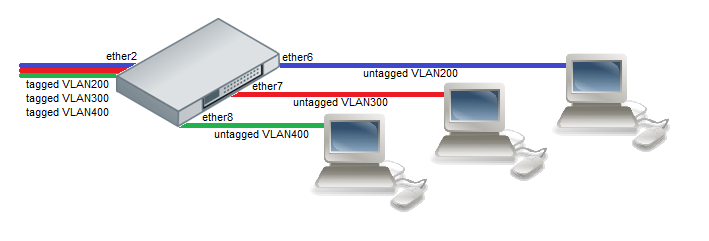
画像を説明しましょう:タグ付きパケットはether2ポート(トランクポート)に到着し、ブランド化されたパケットはether6-ether8ポート(アクセスポートはクライアントポート)から送信されます。
実際に動作するデバイスから構成を取得するため、画像との完全な対応はありません。
RB951Ui-2HnD
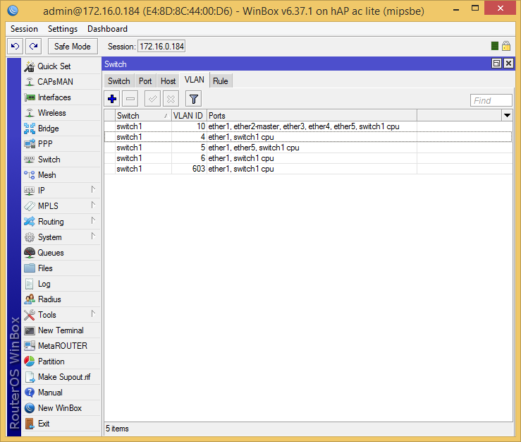
構成:タグ付きパケットがether1(VID:4,5,6,10、603)に到達し、ストリップされたVID:10がether2-ether4ポートから送信され、ストリップされたVID:5がether5から送信され、VID:603は現在使用されておらず、特別なポートswitch1-cpuはすべてのパケットを受け入れます。
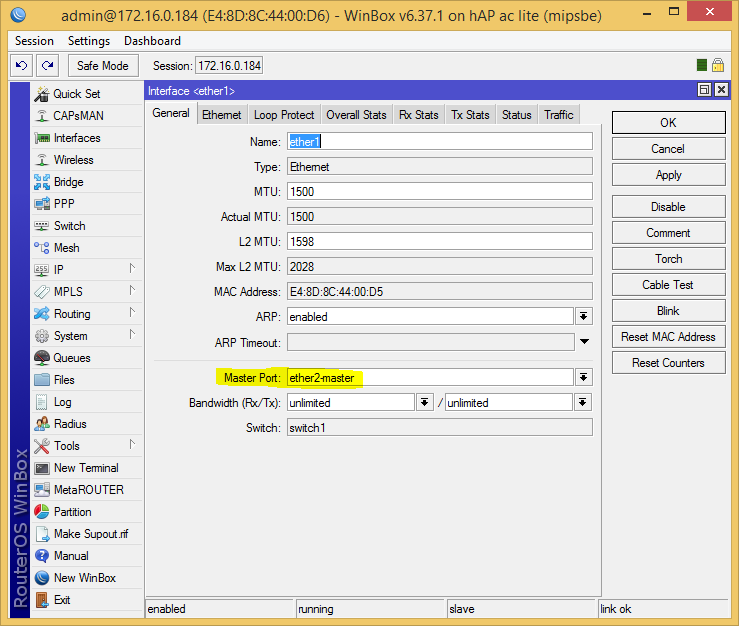
まず、スイッチンググループを作成します。そのために、すべてのインターフェイス(デフォルトではether2-master)にマスターポートを設定します。これにより、これらのポートをスイッチの制御に割り当てます。
/interface ethernet set ether1 master-port=ether2-master
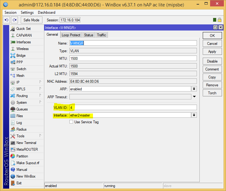
他のみんなも同様です。 遅延することなく、マスターポートで(これがCPUからこのVLANにアクセスする方法です。実際、switch1-cpuに関連付けます)必要なVLANを一時停止します。
/interface vlan add interface=ether2-master \ name=V-210 vlan-id=10 add interface=ether2-master \ name=V-MNGR vlan-id=4 add interface=ether2-master \ name=V-PR1 vlan-id=603 add interface=ether2-master \ name=V-WL vlan-id=5 add arp=enabled arp-timeout=auto disabled=no interface=ether2-master \ loop-protect=default loop-protect-disable-time=5m \ loop-protect-send-interval=5s mtu=1500 name=V-WLG use-service-tag=no \ vlan-id=6
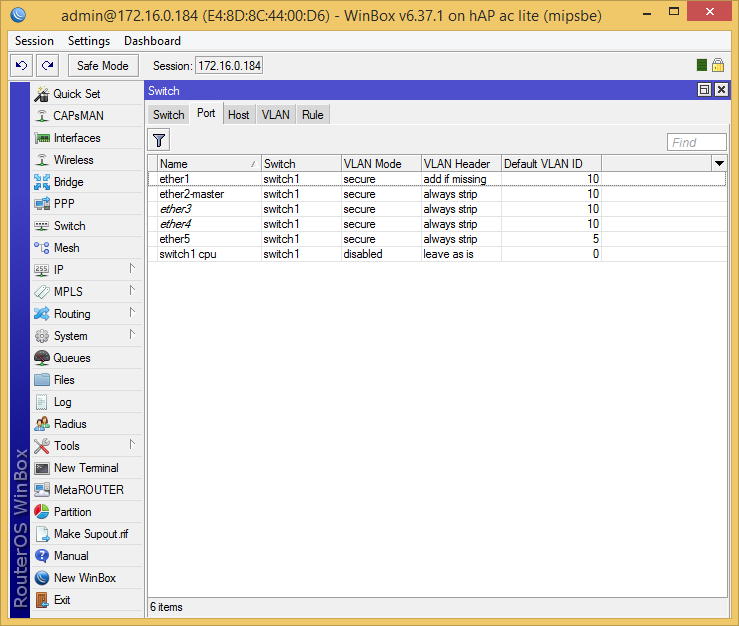
次に、ポートでパケットを処理するためのポリシー(デフォルトのVLAN番号)、ドロップするもの、ストリップするもの、スカーフを結ぶ場所を定義します。
/interface ethernet switch port set ether1 default-vlan-id=10 vlan-header=add-if-missing vlan-mode=secure set ether2-master default-vlan-id=10 vlan-header=always-strip vlan-mode=secure set ether3 default-vlan-id=10 vlan-header=always-strip vlan-mode=secure set ether4 default-vlan-id=10 vlan-header=always-strip vlan-mode=secure set ether5 default-vlan-id=5 vlan-header=always-strip vlan-mode=secure set switch1-cpu default-vlan-id=0 vlan-header=leave-as-is vlan-mode=disabled
VlanテーブルセクションのWikiのパラメーターについて読むことができます。
次に、チップがタグを処理するVLANテーブルを作成します。
/interface ethernet switch vlan add ports=ether1,ether2-master,ether3,ether4,ether5,switch1-cpu switch=switch1 vlan-id=10 add ports=ether1,switch1-cpu switch=switch1 vlan-id=4 add ports=ether1,ether5,switch1-cpu switch=switch1 vlan-id=5 add ports=ether1,switch1-cpu switch=switch1 vlan-id=6 add ports=ether1,switch1-cpu switch=switch1 vlan-id=603
これですべてです。現在、VLANはスイッチングチップで提供されています。残念ながら、RB951Ui-2HnDにはそれほど大きな機能はありません。たとえば、ハイブリッドポートを作成できない場合、ブリッジに松葉杖の森を構築する必要があります。
CRS125-24G-1S-2HnD
ここで、スイッチングチップは完全に異なっており、さらに多くのことができます。
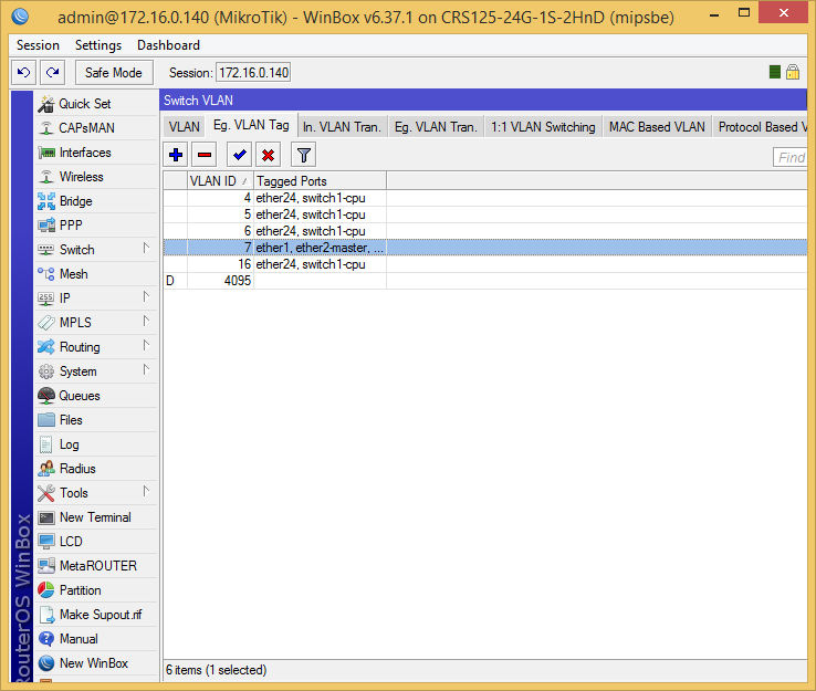
構成:タグ付きパケットはether24(VID:4,5,6,7,16)に到着し、VIDを除去します:16および服を着たVLAN:7はether1-ether23ポートから送信され(2番目の例)、特別なswitch1-cpuポートは受け入れます任意のパッケージ。
まず、スイッチンググループを作成します。そのために、すべてのインターフェイス(デフォルトではether2-master)にマスターポートを設定します。これにより、これらのポートをスイッチの制御に割り当てます。
/interface ethernet set ether1 master-port=ether2-master
他のみんなも同様です。 マスターポートで必要なVLANをハングさせます。
/interface vlan add interface=ether2-master \ name=V-MNGR vlan-id=4 add interface=ether2-master \ name=V-WL vlan-id=5 add interface=ether2-master \ name=V-WLG vlan-id=6
次に、チップがタグを処理するVLANテーブルを作成します。
/interface ethernet switch vlan add learn=yes ports="ether24,switch1-cpu" vlan-id=4 add learn=yes ports="ether24,switch1-cpu" vlan-id=5 add learn=yes ports="ether24,switch1-cpu" vlan-id=6 add learn=yes ports="ether1,ether2-mast\ er,ether3,ether4,ether5,ether6,ether7,ether8,ether9,ether10,ether11,ether1\ 2,ether13,ether14,ether15,ether16,ether17,ether18,ether19,ether20,ether21,\ ether22,ether23,ether24,switch1-cpu" vlan-id=7 add learn=yes ports="ether1,ether2-mast\ er,ether3,ether4,ether5,ether6,ether7,ether8,ether9,ether10,ether11,ether1\ 2,ether13,ether14,ether15,ether16,ether17,ether18,ether19,ether20,ether21,\ ether22,ether23,ether24,switch1-cpu" vlan-id=16

次に、ポートでパケットを処理するためのポリシーを設定します。ここではすべてが充実しており、ポリシーは個別に設定されています。
終了時に対応するVLANが適用されるポートを定義します。
/interface ethernet switch egress-vlan-tag add tagged-ports=ether24,switch1-cpu vlan-id=4 add tagged-ports=ether24,switch1-cpu vlan-id=5 add tagged-ports=ether24,switch1-cpu vlan-id=6 add tagged-ports=ether24,switch1-cpu vlan-id=16
次に、どのポートで発信VLANを削除する必要があります。
/interface ethernet switch egress-vlan-translation add customer-vid=16 new-customer-vid=0 ports="ether1,ether2-master,ether3,ether4,ether5,ether6\ ,ether7,ether8,ether9,ether10,ether11,ether12,ether13,ether14,ether15,ethe\ r16,ether17,ether18,ether19,ether20,ether21,ether22,ether23"

文字通り、これは次のように説明されます:VID:16、ポート1から23の場合、新しいVID:0(ストリップ)をインストールします。
次に、どのポートで、着信パケットをVLANに配置する必要があります。
/interface ethernet switch ingress-vlan-translation add customer-vid=0 new-customer-vid=16 \ ports="ether1,ether2-master,ether3,ether4,ether5,ether6,ether7,ether8,ethe\ r9,ether10,ether11,ether12,ether13,ether14,ether15,ether16,ether17,ether18\ ,ether19,ether20,ether21,ether22,ether23"
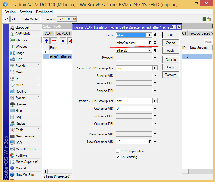
文字通り、これは次のように説明されています:VID:0(パッケージが削除される)、ポート1から23、新しいVIDをインストールする:16(装着)。
それだけです
例2(トランクおよびハイブリッドポート)

ここでは、CRS125-24G-1S-2HnDのみを検討しますが、残念ながら、RB951Ui-2HnDはスイッチングチップでこれを行うことができません。
したがって、前の例から完全にkonfを取り、そのようなルールを追加します。
/interface ethernet switch egress-vlan-tag add tagged-ports="ether1,ether2-master,ether3,ether4,ether5,ether6\ ,ether7,ether8,ether9,ether10,ether11,ether12,ether13,ether14,ether15,ethe\ r16,ether17,ether18,ether19,ether20,ether21,ether22,ether23,ether24" \ vlan-id=7