ここからコアコードとアイデアを入手しました。
1. Satia Komatineni、Dave Macklin、Said Hashimi。 プロフェッショナル向けのAndroid 3。 タブレットおよびスマートフォン用のアプリケーションを作成します。 英語から -M。:LLC "I.D. Williams。" 2012-1,024 p。
2. http://www.learnopengles.com/android-lesson-one-getting-started/
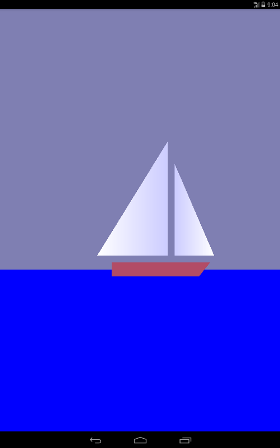
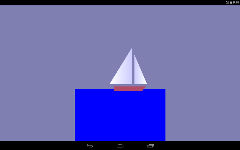
最初のレッスン(こちらhttps://habrahabr.ru/post/278895/またはこちらalbatrossgames.blogspot.com/2016/03/opengl-es-2-android-1-opengl.html#moreを ご覧ください ) OpenGL ESを使用して1色で画面を塗りつぶす方法を学びました。 今度は三角形を描くか、三角形を使って、左から右に循環するヨットを描きます。
なぜ三角形なのか? 実際、OpenGLには、ドット、線、三角形の3つのグラフィックプリミティブしかありません。 ヨットの船体(台形)と海(長方形)も三角形を使用して描画されます。 ご存知のように、空間内のポイントは3つの座標(x、y、z)によって決定されます。 図面は平らであるため、図面のすべてのポイントで、0z軸に沿った1つの座標(画面の平面に垂直であり、私たちに向かっています)はゼロになります。 たとえば、大きな帆(メインセール)の2つの極点の0xおよび0y軸に沿った座標を示しました。
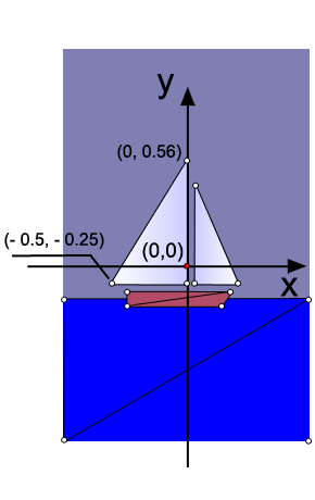
コードでは、洞窟の3つのポイントの定義は次のようになります。
// this triangle is white-blue. First sail is mainsail final float[] triangle1VerticesData = { // X, Y, Z, // R, G, B, A -0.5f, -0.25f, 0.0f, 1.0f, 1.0f, 1.0f, 1.0f, 0.0f, -0.25f, 0.0f, 0.8f, 0.8f, 1.0f, 1.0f, 0.0f, 0.56f, 0.0f, 0.8f, 0.8f, 1.0f, 1.0f};
ご覧のとおり、浮動小数点データ配列が作成されます。 各ポイントについて、その座標と配色が示されます。 最初のポイントは白なので、赤、緑、青の重み係数は同じで1に等しくなりますが、他の2つのピークは美しさのために青になります。 ドットは反時計回りにバイパスします
OpenGLの座標の次元は任意であり、実際にはデバイスの画面上の幅と高さのピクセル数によって決定されます。
ここで、OpenGLのポイントデータを転送するバッファーを作成する必要があります。 これは、OpenGLがCに似た言語で書かれているためです。 したがって、OpenGLが理解できる別の形式にデータを変換し、メモリを割り当てます。
/** How many bytes per float. */ private final int mBytesPerFloat = 4; // Initialize the buffers. mTriangle1Vertices = ByteBuffer.allocateDirect(triangle1VerticesData.length * mBytesPerFloat) .order(ByteOrder.nativeOrder()).asFloatBuffer(); mTriangle1Vertices.put(triangle1VerticesData).position(0);
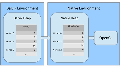
各部分を見てみましょう。 まず、ByteBuffer.allocateDirect()を使用してマシンメモリのブロックを割り当てました。 このメモリはガベージコレクターによって管理されません(これは重要です)。 メモリブロックのサイズをバイト単位でメソッドに伝える必要があります。 頂点はfloat変数として配列に格納され、floatごとに4バイトを占有するため、triangle1VerticesData.length * mBytesPerFloatを渡します。 (プライベート最終int mBytesPerFloat = 4;を思い出してください。)
次の行は、バイトバッファにマシンコードでバイトを整理する方法を示しています。 32ビット整数など、複数のバイトにまたがる値になると、たとえば最上位の値から最下位の値まで、バイトを異なる順序で書き込むことができます。 これは、左から右へ、または右から左へと大量のスペルを入力するようなものです。 気にしませんが、重要なことは、システムと同じ順序を使用することです。 注文(ByteOrder.nativeOrder())を呼び出してこれを整理します。 最後に、個々のバイトを直接処理しないことが最善です。 フロートを処理したいので、FloatBuffer()を呼び出してメインバイトを含むFloatBufferを取得します。 次に、ゼロ位置から開始して、mTriangle1Vertices.put(triangle1VerticesData).position(0);を呼び出して、Dalvikメモリからマシンメモリにデータをコピーします。
プロセスが停止するとメモリが解放されるため、心配する必要はありません。
行列を理解する
マトリックスを理解するための良いレッスンはwww.songho.ca/opengl/gl_transform.htmlです
マトリックスを理解するには、まずOpenGLでオブジェクトを「見る」方法を理解する必要があります。
カメラを持って、帆船の写真を撮りたいと想像してください。
カメラをT.K.に置きます。この点を視点と呼びます。 コードで視点を指定しない場合、カメラはデフォルトで座標(0,0,0)のT.O.になります。
コードでカメラの位置がどのように設定されているかを見てみましょう。
@Override public void onSurfaceCreated(GL10 glUnused, EGLConfig config) { // Set the background clear color to gray. GLES20.glClearColor(0.5f, 0.5f, 0.7f, 1.0f); // Position the eye behind the origin. final float eyeX = 0.0f; final float eyeY = 0.0f; final float eyeZ = 1.5f; // We are looking toward the distance final float lookX = 0.0f; final float lookY = 0.0f; final float lookZ = -5.0f; // Set our up vector. This is where our head would be pointing were we holding the camera. final float upX = 0.0f; final float upY = 1.0f; final float upZ = 0.0f; // Set the view matrix. This matrix can be said to represent the camera position. // NOTE: In OpenGL 1, a ModelView matrix is used, which is a combination of a model and // view matrix. In OpenGL 2, we can keep track of these matrices separately if we choose. Matrix.setLookAtM(mViewMatrix, 0, eyeX, eyeY, eyeZ, lookX, lookY, lookZ, upX, upY, upZ);
最初は、最初のレッスンで行ったのと同様に、背景色を青灰色に設定します。
GLES20.glClearColor(0.5f, 0.5f, 0.7f, 1.0f);
次に、カメラを配置し、実際にT.Kの座標を示しました。 ご覧のとおり、カメラは0z軸に沿って1.5単位シフトします(距離OK)。
final float eyeX = 0.0f; final float eyeY = 0.0f; final float eyeZ = 1.5f;
次のコード行では、カメラが見ているポイントの座標を示しています。
final float lookX = 0.0f; final float lookY = 0.0f; final float lookZ = -5.0f;
次のコード行は、カメラの向きまたはベクトルの位置アップを決定します。 翻訳が失敗したため、さまざまな記事でこの問題が不正確になりました。 今のコードでは
final float upX = 0.0f; final float upY = 1.0f; final float upZ = 0.0f;
これは、カメラが通常配置されることを意味します。したがって、水平なテーブルに置いて、t.0でヨットを見る場合。

T.O.からのように、カメラから3つのベクトルが出てくるとします。 重み係数の最終フロートupY = 1.0fを設定したら、OpenGLに、0U軸が上向きになり、記事の冒頭のように画像が表示されることを伝えます。
しかし、これらの要素を入れると
final float upX = 1.0f; final float upY = 1.0f; final float upZ = 0.0f;
エミュレータで次のように表示されます。 帆船は上り坂に登ります。
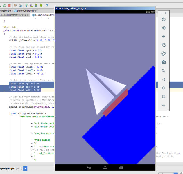
0z軸を見ると、カメラは反時計回りに45度回転しました。 このような組み合わせを作成すると
final float upX = 1.0f; final float upY = 0.0f; final float upZ = 0.0f;
カメラの0x軸が見上げられ、ボートが垂直に上に向かって航行します。
すべてのデータをsetLookAtMメソッドに渡します。
Matrix.setLookAtM(mViewMatrix、0、eyeX、eyeY、eyeZ、lookX、lookY、lookZ、upX、upY、upZ);
可視カメラのボリューム
次のコードを検討してください。
@Override public void onSurfaceChanged(GL10 glUnused, int width, int height) { // Set the OpenGL viewport to the same size as the surface. GLES20.glViewport(0, 0, width, height); // Create a new perspective projection matrix. The height will stay the same // while the width will vary as per aspect ratio. final float ratio = (float) width / height; final float left = -ratio; final float right = ratio; final float bottom = -1.0f; final float top = 1.0f; final float near = 1.0f; final float far = 10.0f; Matrix.frustumM(mProjectionMatrix, 0, left, right, bottom, top, near, far); }
onSurfaceChangedメソッドを使用すると、デバイス自体の向きの変更を練習できます。
エミュレータでガジェットをオンにして、そのような画像を見てみましょう
あまり美しくありませんが、基本的には私たちが描いたものです。
次のコード行は画面サイズを設定します。 まず、画面の左下隅の座標(0,0)を設定してから、画面の幅と高さを設定します。
GLES20.glViewport(0、0、幅、高さ);
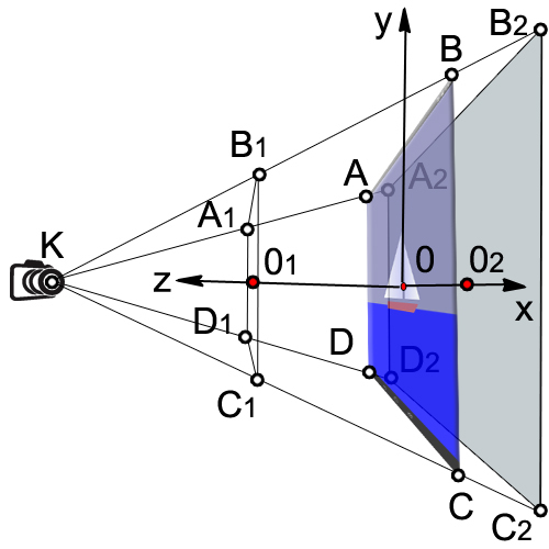
もう一度図面を見てみましょう。
カメラが見る体積は、角錐台の体積(A 1 、B 1 、C 1 、D 1 、A 2 、B 2 、C 2 、D 2 )に囲まれています。
最初に、デバイスの幅と高さの比率(比率)を見つけます。
最終フロート比=(フロート)幅/高さ;
次に、可視の平行六面体(A 1 、B 1 、C 1 、D 1 )の左側と右側の0xに沿って座標を設定します。
最終フロート左= -ratio;
最終フロート右=比率;
ボックスの下側と上側の0yに沿って座標を設定します(A 1 、B 1 、C 1 、D 1 )。
最終フロート底= -1.0f;
最終フロートトップ= 1.0f;
カメラから前面までの距離(KO 1 )
最終フロート= 1.0f付近;
カメラから背面までの距離(KO 2 )
最終フロートfar = 10.0f;
マトリックス変換を適用する
Matrix.frustumM(mProjectionMatrix、0、左、右、下、上、近く、遠い);
使用するマトリックスにはいくつかの異なるタイプがあります。
1.モデルのマトリックス。 このマトリックスは、モデルを「世界」のどこかに配置するために使用されます。 たとえば、車のモデルがあり、それを東1000 mの距離に配置する場合、モデルマトリックスを使用します。
2.ビューマトリックス。 このマトリックスはカメラです。 東に1000 mに位置する車を見たい場合は、1000 m東に移動する必要があります。 または、動かずに残りの世界を1000 m西に移動できます。 これを行うには、ビューマトリックスを使用します。
3.射影行列。 画面はフラットなので、最終的に画面上のビューの「プロジェクト」に変換し、3Dパースペクティブを取得する必要があります。 これを行うには、射影行列を使用します。
頂点シェーダーとフラグメントシェーダーの定義
OpenGL ES 2.0の最も単純な図面でも、シェーダーと呼ばれるソフトウェアセグメントの作成が必要です。 シェーダーはOpenGL ES 2.0のコアを形成します。 頂点は頂点シェーダーによって処理され、頂点ポイントのみを処理します。 頂点間のスペースはフラグメントシェーダーを使用して処理され、画面上のすべてのピクセルを処理します。
シェーダーを記述するために、OpenGL Shading Language(GLSL)が使用されます。
各シェーダーは、主に入力、出力、およびプログラムで構成されています。 まず、フォームを定義します。これは、すべての変換を含む結合行列です。 これはすべての頂点に対して一定であり、それらをスクリーンに投影するために使用されます。 次に、位置と色の2つの属性を定義します。 これらの属性は、前に定義したバッファーから読み取られ、各頂点の位置と色を指定します。 次に、三角形全体の値を補間してフラグメントシェーダーに渡すバリエーション(色の変更)を定義します。 フラグメントシェーダーに関しては、各ピクセルの補間値が含まれます。
頂点が赤、緑、青になり、画面上のサイズが10ピクセルを占める三角形を特定したとします。 フラグメントシェーダーを実行すると、ピクセルごとに異なる変化する色が含まれます。 ある時点で、変更は赤になりますが、赤と青の中間では、マゼンタ色になる場合があります。
頂点シェーダーを検討してください
final String vertexShader = "uniform mat4 u_MVPMatrix; \n" // A constant representing the combined model/view/projection matrix. + "attribute vec4 a_Position; \n" // Per-vertex position information we will pass in. + "attribute vec4 a_Color; \n" // Per-vertex color information we will pass in. + "varying vec4 v_Color; \n" // This will be passed into the fragment shader. + "void main() \n" // The entry point for our vertex shader. + "{ \n" + " v_Color = a_Color; \n" // Pass the color through to the fragment shader. // It will be interpolated across the triangle. + " gl_Position = u_MVPMatrix \n" // gl_Position is a special variable used to store the final position. + " * a_Position; \n" // Multiply the vertex by the matrix to get the final point in + "} \n"; // normalized screen coordinates.
ユニフォームを介して、計算に使用できる外部データがシェーダーに転送されます。 ユニフォームは読み取り専用で使用できます。 ユニフォームは、頂点シェーダーとフラグメントシェーダーの両方に渡すことができます。 この場合、ユニフォームは1つだけです。これは、model-view-projection u_MVPMatrixのマトリックスであり、頂点シェーダーに渡されます。 mat4キーワードは、浮動小数点数で構成される4x4マトリックスであることを意味します。 ユニフォームは特定の頂点に決して関連付けられておらず、グローバル定数です。 ユニフォームの名前には、通常、接頭辞u_が使用されます。
属性は、頂点の属性です。 頂点にはさまざまな属性を設定できます。 たとえば、空間内の位置の座標、法線ベクトルの座標、色。 さらに、任意の属性を頂点シェーダーに渡すことができます。 属性は頂点のプロパティであるため、各頂点に指定する必要があることを理解することが重要です。 属性は頂点シェーダーにのみ渡されます。 属性は、頂点シェーダーに対して読み取り専用です。 フラグメントシェーダーでは属性を定義できません。 便宜上、プレフィックスa_で属性を示します。
頂点シェーダーで3つの属性を定義します。
属性vec4 a_Position;
変数a_Positionは、頂点の位置(座標)を処理する頂点属性です。これは4コンポーネントベクトル(vec4)です。
頂点カラー属性
属性vec4 a_Color;
色補間属性
変化するvec4 v_Color;
メイン関数コードをより詳細に検討してください。
v_Color = a_Color;
頂点の色に関する情報をフラグメントシェーダーに渡します。
gl_Position = u_MVPMatrix * a_Position;
マトリックスを使用して頂点の位置を変換し、新しい変数gl_Positionに書き込みます。
gl_Positionシステム変数は、スクリーンプレーンに投影される頂点の座標を定義する4コンポーネントベクトルです。 gl_Position変数は頂点シェーダーで定義する必要があります。そうしないと、画面に何も表示されません。
フラグメントシェーダーから始めましょう。
final String fragmentShader = "precision mediump float; \n" // Set the default precision to medium. We don't need as high of a // precision in the fragment shader. + "varying vec4 v_Color; \n" // This is the color from the vertex shader interpolated across the // triangle per fragment. + "void main() \n" // The entry point for our fragment shader. + "{ \n" + " gl_FragColor = v_Color; \n" // Pass the color directly through the pipeline. + "} \n";
フラグメントシェーダーの場合、高い精度は必要ないため、デフォルトの精度は平均に設定されています。 頂点シェーダーでは、デフォルトで精度が高くなっています。
精密ミディアムフロート;
フラグメントシェーダーの最終的な目標は、ピクセルの色を取得することです。 計算されたピクセルカラーはgl_FragColorシステム変数に書き込まれる必要があります。 最も単純な例では、フラグメントシェーダーでピクセルカラーを計算せず、頂点の色から補間によって取得したカラーv_colorの値を単に割り当てます。
gl_FragColor = v_color;
OpenGLでのシェーダーのロード
// Load in the vertex shader. int vertexShaderHandle = GLES20.glCreateShader(GLES20.GL_VERTEX_SHADER); if (vertexShaderHandle != 0) { // Pass in the shader source. GLES20.glShaderSource(vertexShaderHandle, vertexShader); // Compile the shader. GLES20.glCompileShader(vertexShaderHandle); // Get the compilation status. final int[] compileStatus = new int[1]; GLES20.glGetShaderiv(vertexShaderHandle, GLES20.GL_COMPILE_STATUS, compileStatus, 0); // If the compilation failed, delete the shader. if (compileStatus[0] == 0) { GLES20.glDeleteShader(vertexShaderHandle); vertexShaderHandle = 0; } } if (vertexShaderHandle == 0) { throw new RuntimeException("Error creating vertex shader."); }
プログラムで頂点シェーダーとフラグメントシェーダーをリンクする
// Create a program object and store the handle to it. int programHandle = GLES20.glCreateProgram(); if (programHandle != 0) { // Bind the vertex shader to the program. GLES20.glAttachShader(programHandle, vertexShaderHandle); // Bind the fragment shader to the program. GLES20.glAttachShader(programHandle, fragmentShaderHandle); // Bind attributes GLES20.glBindAttribLocation(programHandle, 0, "a_Position"); GLES20.glBindAttribLocation(programHandle, 1, "a_Color"); // Link the two shaders together into a program. GLES20.glLinkProgram(programHandle); // Get the link status. final int[] linkStatus = new int[1]; GLES20.glGetProgramiv(programHandle, GLES20.GL_LINK_STATUS, linkStatus, 0); // If the link failed, delete the program. if (linkStatus[0] == 0) { GLES20.glDeleteProgram(programHandle); programHandle = 0; } } if (programHandle == 0) { throw new RuntimeException("Error creating program."); }
頂点シェーダーとフラグメントシェーダーを使用する前に、プログラムでそれらをリンクする必要があります。 これが、頂点シェーダー出力をフラグメントシェーダー入力に接続するものです。 これにより、プログラムからの入力を渡し、シェーダーを使用して図形を描画できます。
新しいプログラムオブジェクトを作成し、成功した場合は、シェーダーをアタッチします。 位置と色のデータを属性として渡したいので、これらの属性を関連付ける必要があります。 次に、シェーダーを接続します。
//New class members /** This will be used to pass in the transformation matrix. */ private int mMVPMatrixHandle; /** This will be used to pass in model position information. */ private int mPositionHandle; /** This will be used to pass in model color information. */ private int mColorHandle; @Override public void onSurfaceCreated(GL10 glUnused, EGLConfig config) { ... // Set program handles. These will later be used to pass in values to the program. mMVPMatrixHandle = GLES20.glGetUniformLocation(programHandle, "u_MVPMatrix"); mPositionHandle = GLES20.glGetAttribLocation(programHandle, "a_Position"); mColorHandle = GLES20.glGetAttribLocation(programHandle, "a_Color"); // Tell OpenGL to use this program when rendering. GLES20.glUseProgram(programHandle); }
プログラムを正常にリンクしたら、いくつかの大きなタスクを完了し、実際に使用できるようになります。 最初のタスクはリンクを取得することで、プログラムにデータを転送できます。 次に、描画の進行中にこのプログラムを使用するようOpenGLに指示します。 このチュートリアルでは1つのプログラムのみを使用するため、onDrawFrame()の代わりにonSurfaceCreated()に配置できます。
透視投影のインストール
// New class members /** Store the projection matrix. This is used to project the scene onto a 2D viewport. */ private float[] mProjectionMatrix = new float[16]; @Override public void onSurfaceChanged(GL10 glUnused, int width, int height) { // Set the OpenGL viewport to the same size as the surface. GLES20.glViewport(0, 0, width, height); // Create a new perspective projection matrix. The height will stay the same // while the width will vary as per aspect ratio. final float ratio = (float) width / height; final float left = -ratio; final float right = ratio; final float bottom = -1.0f; final float top = 1.0f; final float near = 1.0f; final float far = 10.0f; Matrix.frustumM(mProjectionMatrix, 0, left, right, bottom, top, near, far); }
onSurfaceChanged()メソッドは、少なくとも1回、およびサーフェスが変更されるたびに呼び出されます。 スクリーン上で投影が変更されるたびに投影マトリックスをリセットする必要があるため、onSurfaceChanged()はこれを行うのに最適な場所です。
画面にオブジェクトを表示する
出力はonDrawFrameメソッドで生成されます(GL10 glUnused)
三角形が0x軸に沿って移動するために、変位行列を適用し、各表面の更新に対してx変位の0.001増加を指定します。 xが1または画面の右端に達したらすぐにゼロにします。
Matrix.translateM(mModelMatrix、0、x + 0.3f、0.0f、0.0f);
drawTriangle(mTriangle2Vertices);
if(x <= 1){x =(float)(x + 0.001);}
その他{x = 0;}
2回目のレッスンでは十分すぎると思います。 多くの質問が見落とされており、それらの理解は後で来るでしょう。
Android Studioでレッスンを実行します。
前のレッスンのプロジェクトを使用し、このコードを単純にコピーすることをお勧めします。
持っていない場合は、最初のOpen GLプロジェクトを作成します
AndroidManifest.xml
<?xml version="1.0" encoding="utf-8"?> <manifest xmlns:android="http://schemas.android.com/apk/res/android" package="com.adc2017gmail.firstopenglproject"> <application android:allowBackup="true" android:icon="@mipmap/ic_launcher" android:label="@string/app_name" android:supportsRtl="true" android:theme="@style/AppTheme"> <uses-feature android:glEsVersion="0x00020000" android:required="true" /> <activity android:name=".FirstOpenGLProjectActivity"> <intent-filter> <action android:name="android.intent.action.MAIN" /> <category android:name="android.intent.category.LAUNCHER" /> </intent-filter> </activity> </application> </manifest>
FirstOpenGLProjectActivity.java
package com.adc2017gmail.firstopenglproject; import android.app.Activity; import android.app.ActivityManager; import android.content.Context; import android.content.pm.ConfigurationInfo; import android.opengl.GLSurfaceView; import android.os.Bundle; public class FirstOpenGLProjectActivity extends Activity { /** Hold a reference to our GLSurfaceView */ private GLSurfaceView mGLSurfaceView; @Override public void onCreate(Bundle savedInstanceState) { super.onCreate(savedInstanceState); mGLSurfaceView = new GLSurfaceView(this); // Check if the system supports OpenGL ES 2.0. final ActivityManager activityManager = (ActivityManager) getSystemService(Context.ACTIVITY_SERVICE); final ConfigurationInfo configurationInfo = activityManager.getDeviceConfigurationInfo(); final boolean supportsEs2 = configurationInfo.reqGlEsVersion >= 0x20000; if (supportsEs2) { // Request an OpenGL ES 2.0 compatible context. mGLSurfaceView.setEGLContextClientVersion(2); // Set the renderer to our demo renderer, defined below. mGLSurfaceView.setRenderer(new LessonOneRenderer()); } else { // This is where you could create an OpenGL ES 1.x compatible // renderer if you wanted to support both ES 1 and ES 2. return; } setContentView(mGLSurfaceView); } @Override protected void onResume() { // The activity must call the GL surface view's onResume() on activity onResume(). super.onResume(); mGLSurfaceView.onResume(); } @Override protected void onPause() { // The activity must call the GL surface view's onPause() on activity onPause(). super.onPause(); mGLSurfaceView.onPause(); } }
LessonOneRenderer.java
package com.adc2017gmail.firstopenglproject; import android.opengl.GLES20; import android.opengl.GLSurfaceView; import android.opengl.Matrix; import java.nio.ByteBuffer; import java.nio.ByteOrder; import java.nio.FloatBuffer; import javax.microedition.khronos.egl.EGLConfig; import javax.microedition.khronos.opengles.GL10; /** * This class implements our custom renderer. Note that the GL10 parameter passed in is unused for OpenGL ES 2.0 * renderers -- the static class GLES20 is used instead. */ public class LessonOneRenderer implements GLSurfaceView.Renderer { /** * Store the model matrix. This matrix is used to move models from object space (where each model can be thought * of being located at the center of the universe) to world space. */ private float[] mModelMatrix = new float[16]; /** * Store the view matrix. This can be thought of as our camera. This matrix transforms world space to eye space; * it positions things relative to our eye. */ private float[] mViewMatrix = new float[16]; /** Store the projection matrix. This is used to project the scene onto a 2D viewport. */ private float[] mProjectionMatrix = new float[16]; /** Allocate storage for the final combined matrix. This will be passed into the shader program. */ private float[] mMVPMatrix = new float[16]; /** Store our model data in a float buffer. */ private final FloatBuffer mTriangle1Vertices; private final FloatBuffer mTriangle2Vertices; private final FloatBuffer mTriangle3Vertices; private final FloatBuffer mTriangle4Vertices; private final FloatBuffer mTriangle5Vertices; private final FloatBuffer mTriangle6Vertices; /** This will be used to pass in the transformation matrix. */ private int mMVPMatrixHandle; /** This will be used to pass in model position information. */ private int mPositionHandle; /** This will be used to pass in model color information. */ private int mColorHandle; /** How many bytes per float. */ private final int mBytesPerFloat = 4; /** How many elements per vertex. */ private final int mStrideBytes = 7 * mBytesPerFloat; /** Offset of the position data. */ private final int mPositionOffset = 0; /** Size of the position data in elements. */ private final int mPositionDataSize = 3; /** Offset of the color data. */ private final int mColorOffset = 3; /** Size of the color data in elements. */ private final int mColorDataSize = 4; private float x; /** * Initialize the model data. */ public LessonOneRenderer() { // Define points for equilateral triangles. // This triangle is white_blue.First sail is mainsail final float[] triangle1VerticesData = { // X, Y, Z, // R, G, B, A -0.5f, -0.25f, 0.0f, 1.0f, 1.0f, 1.0f, 1.0f, 0.0f, -0.25f, 0.0f, 0.8f, 0.8f, 1.0f, 1.0f, 0.0f, 0.56f, 0.0f, 0.8f, 0.8f, 1.0f, 1.0f}; // This triangle is white_blue..The second is called the jib sail final float[] triangle2VerticesData = { // X, Y, Z, // R, G, B, A -0.25f, -0.25f, 0.0f, 0.8f, 0.8f, 1.0f, 1.0f, 0.03f, -0.25f, 0.0f, 1.0f, 1.0f, 1.0f, 1.0f, -0.25f, 0.4f, 0.0f, 0.8f, 0.8f, 1.0f, 1.0f}; // This triangle3 is blue. final float[] triangle3VerticesData = { // X, Y, Z, // R, G, B, A -1.0f, -1.5f, 0.0f, 0.0f, 0.0f, 1.0f, 1.0f, 1.0f, -0.35f, 0.0f, 0.0f, 0.0f, 1.0f, 1.0f, -1.0f, -0.35f, 0.0f, 0.0f, 0.0f, 1.0f, 1.0f}; // This triangle4 is blue. final float[] triangle4VerticesData = { // X, Y, Z, // R, G, B, A -1.0f, -1.5f, 0.0f, 0.0f, 0.0f, 1.0f, 1.0f, 1.0f, -1.5f, 0.0f, 0.0f, 0.0f, 1.0f, 1.0f, 1.0f, -0.35f, 0.0f, 0.0f, 0.0f, 1.0f, 1.0f}; // This triangle5 is brown. final float[] triangle5VerticesData = { // X, Y, Z, // R, G, B, A -0.4f, -0.3f, 0.0f, 0.7f, 0.3f, 0.4f, 1.0f, -0.4f, -0.4f, 0.0f, 0.7f, 0.3f, 0.4f, 1.0f, 0.3f, -0.3f, 0.0f, 0.7f, 0.3f, 0.4f, 1.0f}; // This triangle6 is brown. final float[] triangle6VerticesData = { // X, Y, Z, // R, G, B, A -0.4f, -0.4f, 0.0f, 0.7f, 0.3f, 0.4f, 1.0f, 0.22f, -0.4f, 0.0f, 0.7f, 0.3f, 0.4f, 1.0f, 0.3f, -0.3f, 0.0f, 0.7f, 0.3f, 0.4f, 1.0f}; // Initialize the buffers. mTriangle1Vertices = ByteBuffer.allocateDirect(triangle1VerticesData.length * mBytesPerFloat) .order(ByteOrder.nativeOrder()).asFloatBuffer(); mTriangle2Vertices = ByteBuffer.allocateDirect(triangle2VerticesData.length * mBytesPerFloat) .order(ByteOrder.nativeOrder()).asFloatBuffer(); mTriangle3Vertices = ByteBuffer.allocateDirect(triangle3VerticesData.length * mBytesPerFloat) .order(ByteOrder.nativeOrder()).asFloatBuffer(); mTriangle4Vertices = ByteBuffer.allocateDirect(triangle4VerticesData.length * mBytesPerFloat) .order(ByteOrder.nativeOrder()).asFloatBuffer(); mTriangle5Vertices = ByteBuffer.allocateDirect(triangle5VerticesData.length * mBytesPerFloat) .order(ByteOrder.nativeOrder()).asFloatBuffer(); mTriangle6Vertices = ByteBuffer.allocateDirect(triangle6VerticesData.length * mBytesPerFloat) .order(ByteOrder.nativeOrder()).asFloatBuffer(); mTriangle1Vertices.put(triangle1VerticesData).position(0); mTriangle2Vertices.put(triangle2VerticesData).position(0); mTriangle3Vertices.put(triangle3VerticesData).position(0); mTriangle4Vertices.put(triangle4VerticesData).position(0); mTriangle5Vertices.put(triangle5VerticesData).position(0); mTriangle6Vertices.put(triangle6VerticesData).position(0); } @Override public void onSurfaceCreated(GL10 glUnused, EGLConfig config) { // Set the background clear color to gray. GLES20.glClearColor(0.5f, 0.5f, 0.7f, 1.0f); // Position the eye behind the origin. final float eyeX = 0.0f; final float eyeY = 0.0f; final float eyeZ = 1.5f; // We are looking toward the distance final float lookX = 0.0f; final float lookY = 0.0f; final float lookZ = -5.0f; // Set our up vector. This is where our head would be pointing were we holding the camera. final float upX = 0.0f; final float upY = 1.0f; final float upZ = 0.0f; // Set the view matrix. This matrix can be said to represent the camera position. // NOTE: In OpenGL 1, a ModelView matrix is used, which is a combination of a model and // view matrix. In OpenGL 2, we can keep track of these matrices separately if we choose. Matrix.setLookAtM(mViewMatrix, 0, eyeX, eyeY, eyeZ, lookX, lookY, lookZ, upX, upY, upZ); final String vertexShader = "uniform mat4 u_MVPMatrix; \n" // A constant representing the combined model/view/projection matrix. + "attribute vec4 a_Position; \n" // Per-vertex position information we will pass in. + "attribute vec4 a_Color; \n" // Per-vertex color information we will pass in. + "varying vec4 v_Color; \n" // This will be passed into the fragment shader. + "void main() \n" // The entry point for our vertex shader. + "{ \n" + " v_Color = a_Color; \n" // Pass the color through to the fragment shader. // It will be interpolated across the triangle. + " gl_Position = u_MVPMatrix \n" // gl_Position is a special variable used to store the final position. + " * a_Position; \n" // Multiply the vertex by the matrix to get the final point in + "} \n"; // normalized screen coordinates. final String fragmentShader = "precision mediump float; \n" // Set the default precision to medium. We don't need as high of a // precision in the fragment shader. + "varying vec4 v_Color; \n" // This is the color from the vertex shader interpolated across the // triangle per fragment. + "void main() \n" // The entry point for our fragment shader. + "{ \n" + " gl_FragColor = v_Color; \n" // Pass the color directly through the pipeline. + "} \n"; // Load in the vertex shader. int vertexShaderHandle = GLES20.glCreateShader(GLES20.GL_VERTEX_SHADER); if (vertexShaderHandle != 0) { // Pass in the shader source. GLES20.glShaderSource(vertexShaderHandle, vertexShader); // Compile the shader. GLES20.glCompileShader(vertexShaderHandle); // Get the compilation status. final int[] compileStatus = new int[1]; GLES20.glGetShaderiv(vertexShaderHandle, GLES20.GL_COMPILE_STATUS, compileStatus, 0); // If the compilation failed, delete the shader. if (compileStatus[0] == 0) { GLES20.glDeleteShader(vertexShaderHandle); vertexShaderHandle = 0; } } if (vertexShaderHandle == 0) { throw new RuntimeException("Error creating vertex shader."); } // Load in the fragment shader shader. int fragmentShaderHandle = GLES20.glCreateShader(GLES20.GL_FRAGMENT_SHADER); if (fragmentShaderHandle != 0) { // Pass in the shader source. GLES20.glShaderSource(fragmentShaderHandle, fragmentShader); // Compile the shader. GLES20.glCompileShader(fragmentShaderHandle); // Get the compilation status. final int[] compileStatus = new int[1]; GLES20.glGetShaderiv(fragmentShaderHandle, GLES20.GL_COMPILE_STATUS, compileStatus, 0); // If the compilation failed, delete the shader. if (compileStatus[0] == 0) { GLES20.glDeleteShader(fragmentShaderHandle); fragmentShaderHandle = 0; } } if (fragmentShaderHandle == 0) { throw new RuntimeException("Error creating fragment shader."); } // Create a program object and store the handle to it. int programHandle = GLES20.glCreateProgram(); if (programHandle != 0) { // Bind the vertex shader to the program. GLES20.glAttachShader(programHandle, vertexShaderHandle); // Bind the fragment shader to the program. GLES20.glAttachShader(programHandle, fragmentShaderHandle); // Bind attributes GLES20.glBindAttribLocation(programHandle, 0, "a_Position"); GLES20.glBindAttribLocation(programHandle, 1, "a_Color"); // Link the two shaders together into a program. GLES20.glLinkProgram(programHandle); // Get the link status. final int[] linkStatus = new int[1]; GLES20.glGetProgramiv(programHandle, GLES20.GL_LINK_STATUS, linkStatus, 0); // If the link failed, delete the program. if (linkStatus[0] == 0) { GLES20.glDeleteProgram(programHandle); programHandle = 0; } } if (programHandle == 0) { throw new RuntimeException("Error creating program."); } // Set program handles. These will later be used to pass in values to the program. mMVPMatrixHandle = GLES20.glGetUniformLocation(programHandle, "u_MVPMatrix"); mPositionHandle = GLES20.glGetAttribLocation(programHandle, "a_Position"); mColorHandle = GLES20.glGetAttribLocation(programHandle, "a_Color"); // Tell OpenGL to use this program when rendering. GLES20.glUseProgram(programHandle); } @Override public void onSurfaceChanged(GL10 glUnused, int width, int height) { // Set the OpenGL viewport to the same size as the surface. GLES20.glViewport(0, 0, width, height); // Create a new perspective projection matrix. The height will stay the same // while the width will vary as per aspect ratio. final float ratio = (float) width / height; final float left = -ratio; final float right = ratio; final float bottom = -1.0f; final float top = 1.0f; final float near = 1.0f; final float far = 10.0f; Matrix.frustumM(mProjectionMatrix, 0, left, right, bottom, top, near, far); } @Override public void onDrawFrame(GL10 glUnused) { GLES20.glClear(GLES20.GL_DEPTH_BUFFER_BIT | GLES20.GL_COLOR_BUFFER_BIT); // Draw the triangle facing straight on. Matrix.setIdentityM(mModelMatrix, 0); Matrix.translateM(mModelMatrix, 0, x, 0.0f, 0.0f); drawTriangle(mTriangle1Vertices); // Draw triangle_2. Matrix.setIdentityM(mModelMatrix, 0); Matrix.translateM(mModelMatrix, 0, x + 0.3f, 0.0f, 0.0f); drawTriangle(mTriangle2Vertices); if(x<=1){x = (float) (x + 0.001);} else {x=0;} // Draw triangle_3. Matrix.setIdentityM(mModelMatrix, 0); drawTriangle(mTriangle3Vertices); // Draw triangle_4. Matrix.setIdentityM(mModelMatrix, 0); drawTriangle(mTriangle4Vertices); // Draw triangle_5. Boat Matrix.setIdentityM(mModelMatrix, 0); Matrix.translateM(mModelMatrix, 0, x, 0.0f, 0.0f); //Matrix.rotateM(mModelMatrix, 0, 0, 0.0f, 0.0f, 1.0f); drawTriangle(mTriangle5Vertices); // Draw triangle_6. Boat Matrix.setIdentityM(mModelMatrix, 0); Matrix.translateM(mModelMatrix, 0, x, 0.0f, 0.0f); //Matrix.rotateM(mModelMatrix, 0, 0, 0.0f, 0.0f, 1.0f); drawTriangle(mTriangle6Vertices); } /** * Draws a triangle from the given vertex data. * * @param aTriangleBuffer The buffer containing the vertex data. */ private void drawTriangle(final FloatBuffer aTriangleBuffer) { // Pass in the position information aTriangleBuffer.position(mPositionOffset); GLES20.glVertexAttribPointer(mPositionHandle, mPositionDataSize, GLES20.GL_FLOAT, false, mStrideBytes, aTriangleBuffer); GLES20.glEnableVertexAttribArray(mPositionHandle); // Pass in the color information aTriangleBuffer.position(mColorOffset); GLES20.glVertexAttribPointer(mColorHandle, mColorDataSize, GLES20.GL_FLOAT, false, mStrideBytes, aTriangleBuffer); GLES20.glEnableVertexAttribArray(mColorHandle); // This multiplies the view matrix by the model matrix, and stores the result in the MVP matrix // (which currently contains model * view). Matrix.multiplyMM(mMVPMatrix, 0, mViewMatrix, 0, mModelMatrix, 0); // This multiplies the modelview matrix by the projection matrix, and stores the result in the MVP matrix // (which now contains model * view * projection). Matrix.multiplyMM(mMVPMatrix, 0, mProjectionMatrix, 0, mMVPMatrix, 0); GLES20.glUniformMatrix4fv(mMVPMatrixHandle, 1, false, mMVPMatrix, 0); GLES20.glDrawArrays(GLES20.GL_TRIANGLES, 0, 3); } }
1. , , . Android 3 . .: . . – .: «..». 2012 – 1024 .
2. http://www.learnopengles.com/android-lesson-one-getting-started/
3. http://andmonahov.blogspot.com/2012/10/opengl-es-20-1.html
4. https://www.opengl.org/sdk/docs/tutorials/ClockworkCoders/attributes.php
5. https://www.khronos.org/opengles/sdk/docs/reference_cards/OpenGL-ES-2_0-Reference-card.pdf