 ARM Cortex-M3は、おそらく今日の組み込みシステムで最も人気のある32ビットプロセッサコアです。 それに基づくマイクロコントローラーは、多くのメーカーによって製造されています。 この理由は、普遍的でバランスのとれたアーキテクチャであり、その結果、既製のソフトウェアおよびハードウェアソリューションのベースが常に成長しています。
一般的に、Scord Cortex-M3はまったくそうではありませんが、今日、Cortex-M4F-最愛のプロセッサコアの拡張バージョンを詳細に検討することを提案します。 Cortex-M3に基づいたマイクロコントローラーからCortex-M4Fに基づいたクリスタルにプロジェクトを転送するのは非常に簡単ですが、多くのタスクにとってこの移行は努力する価値があります。
カッターの下には、最新のCortexの簡単な概要、Cortex-M4FとCortex-M3を区別するブロックとコマンドの詳細な説明、および実際のタスクでのプロセッサコアの比較があります。異なるコアを持つマイクロコントローラのランプフリッカー周波数を測定します。
レビュー部
連続した世代のARMプロセッサコアが互いにどのように成功したかについて、膨大な数の記事とレビューが書かれています。 ウィキペディアにあるすべてをペイントする理由はありませんが、基本的な事実を思い出させます。
会社ARM Ltd. RISCアーキテクチャを備えたマイクロプロセッサおよびマイクロコントローラコアを開発し、適切な技術を使用して水晶の製造ライセンスを電子部品メーカーに販売しています。 このような製造業者は世界中に何十、何百とあり、その中には国内企業があります。
最新のARMコアは、Cortexという名前で統一されています。
ちなみに、「皮質」という言葉は「大脳皮質」と翻訳されています。これは、臓器の協調作業、思考、および高次の神経活動に関与する構造です。 私の意見では、素晴らしい名前です。
そのため、ARM Cortexプロセッサコアは3つの主要なグループに分かれています。
- Cortex-A-アプリケーションプロセッサ-高性能を必要とするアプリケーション向け。 ほとんどの場合、Linux、Android、および類似のOSを実行します
- Cortex-R-組み込みリアルタイムプロセッサ-リアルタイムアプリケーション用
- Cortex-M-組み込みプロセッサ-組み込みシステム用
最後のグループを考えて、Cortex-M3 / Cortex-M4Fのペアに徐々に近づきます。 合計で、2015年末に、Cortex-M0、-M0 +、-M1、-M3、-M4、-M7の6つのプロセッサコアが発表されました。
-M1はFPGA関連のアプリケーションでのみ設計および使用されるため、Cortex-M1はこのリストからしばしば「除外」されます。 残りのコアには、このような特殊なアプリケーション分野がなく、パフォーマンスが異なります-最も単純な-M0から高性能の-M7です。

Cortex-M0と比較して、Cortex-M0 +には、MPUメモリ保護ユニット、デバッグプログラム用のマイクロトレースバッファーが追加で装備されています。また、周辺ブロックと入出力ラインへの3ステージの単純化されたアクセスの代わりに、2ステージパイプラインがあります。
Cortex-M0およびCortex-M0 +にはシングルバスフォンノイマンアーキテクチャがあり、Cortex-M3コアはすでにハーバードです。 Cortex-M3は、ラインの「若い」代表とはまったく異なり、さらに多くの機能を備えています。
Cortex-M4はまったく同じアーキテクチャで構築されており、「構造的に」Cortex-M3と違いはありません。 違いはサポートされているコマンドシステムにありますが、それについては後で詳しく説明します。 Cortex-M4Fは、FPU浮動小数点ユニットが存在する点で-M4と異なります。
Cortex-M7アーキテクチャは比較的最近のものであり、Cortex-M3 / M4とCortex-M0が異なるのと同様に、Cortex-M3 / M4とは異なります。 6ステージのスーパースカラーパイプライン、データと命令用の個別のキャッシュ、構成可能なTCMメモリ、およびこのコアの他の特徴的な機能は、最高のパフォーマンスを実現するために「シャープ」になっています。 実際、Cortex-M7に基づいたコントローラの機能は、組み込みプロセッサグループの他のコントローラよりもCortex-A5および-R5と比較される可能性が高くなります。 テクノロジーアプリケーションの境界はあいまいになり続けています。
Cortex-Mコアの機能はまったく異なりますが、各コアのコマンドセットには、下位のコアでサポートされているすべてのコマンドが含まれています。 これにより、異なるコアに基づいたソフトウェア互換マイクロコントローラーを開発する機会が提供されます。これは、ほとんどのマイクロコントローラーメーカーが行っていることです。

コアCortex-M0およびCortex-M0 +は、同じコマンドシステムです。 Cortex-M3命令セットには、すべてのCortex-M0コマンドと約100の追加命令が含まれています。 Cortex-M4およびCortex-M7プロセッサコアには、同じ命令セットがあります。Cortex-M3命令セットと、いわゆるDSP命令です。 Cortex-M4Fコアは、Cortex-M4 / -M7セットに加えて、浮動小数点計算命令をサポートし、Cortex-M7F命令セットには、倍精度浮動小数点演算用の14個の命令が含まれています。
理論部
そのため、人気のあるCortex-M3プロセッサコアの最も近い「隣接」は、DSP命令のサポートが追加されたCortex-M4と、FPUを追加して対応するコマンドをサポートするCortex-M4Fです。 DSPおよびFPUコマンドを検討してください。
DSP命令
略語DSPは、ほとんどの場合、デジタルシグナルプロセッサとして解読されます。 デジタル信号処理のタスク用に設計された完全に独立した独立したコントローラーまたはコプロセッサー。 特殊なDSPチップとDSP命令のセットを混同しないでください。 DSPコマンド(Process またはの代わりにデジタル信号処理を表す)は、多数のARMプロセッサコアでサポートされている一連のコマンドであり、デジタル信号処理の一般的な操作に対応しています。
このような操作の最初のグループは、 累積乗算 (Single-cycle Multiply Accumulateまたは単にMAC)です。
最小の場合:累算を伴う乗算は、式S = S + A x Bで記述されます。対応するコマンドは、2つのレジスタと累算器での結果の合計および関連する演算との乗算を記述します。
16ビットおよび32ビット変数の操作が提供され、多くの一般的なデジタル信号処理アルゴリズムで重要な役割を果たします。 たとえば、 FIRフィルター (これは古典的な、たとえばほぼ平凡な)は、累算を伴う乗算のシーケンスです。つまり、その速度は、累算を伴う乗算の速度に直接依存します。
Cortex-M4(F)コアを備えたマイクロコントローラーのすべてのMAC命令は、単一マシンサイクルで実行されます。
DSP命令の2番目のグループは、SIMD(Single Instruction Multiple Data)操作です。これにより、並列計算によるデータ処理の最適化が可能になります。 独立変数のペアは、より大きな次元の単一のレジスタにペアごとに配置され、算術演算は「大きな」レジスタですでに実行されています。
たとえば、 SADD16コマンドでは、16ビットの符号付き数値の2つのペアを同時に加算し、結果を第1オペランドを格納するレジスタに書き込みます。
SADD16 R1, R0
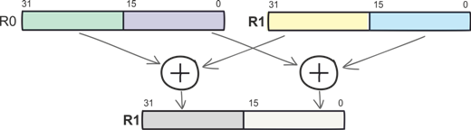
汎用レジスタの容量は32ビットであるため、各レジスタには2つの16ビット変数(ハーフワード)だけでなく、最大4つの8ビット変数(バイト)を含めることができます。 これで、SADD8コマンドが必要な理由を簡単に理解できます。
次に、より複雑な操作を示します。上位のハーフワードを乗算し、下位のハーフワードを乗算し、64ビットの累積でピースを合計します。 SMLALDコマンドはこれらすべてのアクションを記述し、単一マシンサイクルでCortex-M4によって実行されます。 SMLALDは、他の多くのチームと同様に、SIMDに基づいて乗算と累積およびデータ処理を組み合わせます。
SMLALD R6, R8, R5, R1
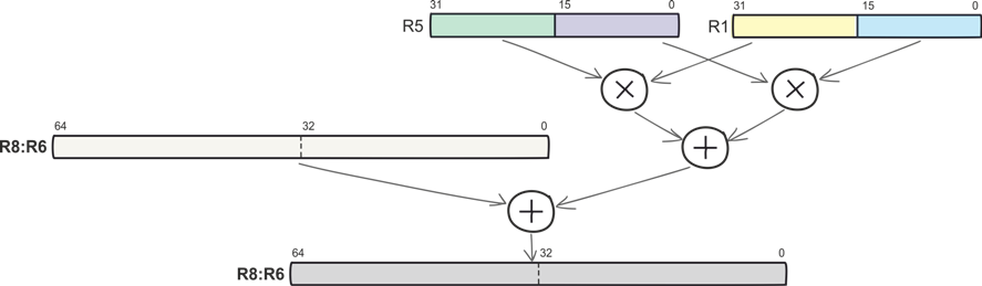
単純なSIMDコマンド(符号付きおよび符号なしの8ビットおよび16ビットの加算および減算など)とSMLALDなどの複雑なコマンドの両方が1マシンサイクルで実行されます。
DSP命令の次のグループは、飽和命令です。 これらはカットオフ操作とも呼ばれ、オーバーフロー保護を表します。 標準コマンドを使用する場合、結果を格納するレジスタは、オーバーフロー時に最初から「リロード」され、飽和を提供するコマンドはオーバーフロー時に、許容最大容量で結果を修正します。 これにより、プログラマがオーバーフローフラグを処理する必要がなくなります。
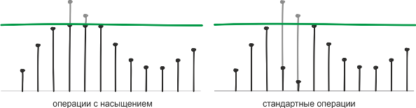
Cortex-M4プロセッサコアの命令には、「通常の」算術演算と飽和を伴う同じ演算の両方があります。 後者の使用は、速度のために計算の精度を犠牲にする可能性のある問題で特に需要があります。 DSPにはこのようなタスクが多数あります。
FPU命令
浮動小数点計算(または任意のポイント)のハードウェアサポートは、Cortex-M4FコアとCortex-Mラインの古い代表の機能です。
浮動小数点計算コマンドを使用すると、実数に対して最大のパフォーマンスで操作を実行できます。 一般に、現在、実数の表現には固定小数点と浮動小数点の2つの形式が使用されています。 前者の場合、整数部と小数部を記録するためのビット数は固定されており、計算は整数の演算に削減されます。後者の場合、数は符号ビット、次数と仮数部の組み合わせとして表されます。
(-1) s * m×b e 、
ここで、sは符号、b-base、eは次数、mは仮数です。
浮動小数点形式の変数の値の範囲がはるかに広いため、信号を処理する場合は、浮動小数点形式を使用することをお勧めします。 FPU操作を使用すると、開発者がビット深度を監視する必要もなくなります。 単精度浮動小数点数形式はIEEE 754標準で記述されており、この表現はCortex-M4Fコアを備えたマイクロコントローラーで使用されます。 許容値の範囲は(10 –38 ... 10 38 )であり、10進数への近似変換が行われます。

ところで、Cortex-M7Fは、倍精度浮動小数点数形式に対して同じ原理を使用しますが、32ビット表現の代わりに64ビット表現を使用します。 桁は11ビット、仮数52になります。
浮動小数点形式がHabréで書かれた複数回使用される理由と理由について( ここでは、優れた記事など)。 おそらく私はこれ以上書くことができないので、先に進みましょう。
組み立てられたDSPおよびFPUコマンドのリスト
Cortex-M4を使用したデータ処理の量を理解するために、規模の感覚をつかむために、DSPおよびFPU命令の完全なリストを学ぶことができます。 これらのテーブルの実用的な価値については大きな疑問がありますが、興味深いものです。
すべてのDSPおよびほとんどのFPU命令は、単一マシンサイクルで実行されます。
Cortex-M4カーネルDSP命令
| チーム | 運営 |
| PKHTB、PKHBT | 必要に応じて、「受信」レジスタの内容をシフトして、あるレジスタから別のレジスタにハーフワードを書き換えます |
| QADD | 飽和した符号付き加算 |
| QADD16 | 2つのオペランドの対応するハーフワードの符号加算(飽和あり) |
| QADD8 | 2つのオペランドの対応するバイトの符号付き加算(飽和あり) |
| QASX | 第2オペランドの下位ハーフワードと第1オペランドの上位ハーフワードの符号付き加算、第1オペランドの下位ハーフワードからの第2オペランドの最上位ハーフワードの符号付き減算(飽和あり)
|
| QDADD | 第2オペランドを2倍にし、結果を第1オペランドと加算する(符号付き、飽和) |
| QDSUB | 第2オペランドを2倍にし、第1オペランドから結果を減算(符号付き、飽和あり) |
| QSAX | 第1オペランドの最上位ハーフワードからの第2オペランドの副ハーフワードの有意な減算+第1オペランドの副ハーフワードと第2オペランドの上位ハーフワードの有意な加算(飽和あり) |
| QSUB | 符号付き減算(飽和あり) |
| QSUB16 | 2つのオペランドの対応するハーフワードの有意な減算(飽和あり) |
| QSUB8 | 2つのオペランドの対応するバイトの有意な減算(飽和あり) |
| SADD16 | 2つのオペランドの対応するハーフワードの大幅な追加 |
| SADD8 | 2つのオペランドの対応するバイトの符号付き加算 |
| サックス | 第1オペランドの上位ハーフワードと第2オペランドの下位ハーフワードの符号付き加算、結果の上位ハーフワードのレコード、結果の下位ハーフワードのエントリを持つ第1オペランドの上位ハーフワードからの第2オペランドの下位ハーフワードの符号付き減算
|
| SEL | GE [3:0]のビットに応じたオペランドからのバイトの選択(算術演算の実行時に「以上」などのさまざまな条件が設定されたときに設定される「フラグ」) |
| SHADD16 | オペランドの対応するハーフワードの符号加算、2つの結果の右への1ビットのシフト |
| SHADD8 | オペランドの対応するバイトの符号付き加算、4つの結果を右に1ビットシフト |
| SHASX | 第1オペランドの最上位ハーフワードと第2オペランドの下位ハーフワードの符号付き加算、指定されたレジスタの最上位ハーフワードに結果を1ビット右シフトで書き込み、第1オペランドの下位ハーフワードから第2オペランドの最上位ハーフワードを大幅に減算し、右シフト1で指定レジスタの下位ハーフワードに結果を記録する少し |
| SHSAX | 第1オペランドの最上位ハーフワードから第2オペランドの下位ハーフワードを有意に減算し、指定したレジスタの下位ハーフワードに結果を1ビット右シフトして書き込み、第2オペランドの上位ハーフワードと第1オペランドの下位ハーフワードを有意に加算し、指定したレジスタの上位ハーフワードに右シフト1で結果を書き込む少し |
| SHSUB16 | 第1オペランドの対応するハーフワードから第2オペランドの上位および下位ハーフワードを大幅に減算し、結果を1ビット右にシフトします。 |
| SHSUB8 | 第1オペランドの対応するバイトから第2オペランドの上位および下位バイトを大幅に減算し、結果を1ビット右にシフトします |
| SMLABB、SMLABT、SMLATB、SMLATT | 2つのオペランドの上位または下位ハーフワードと32ビット累積の乗算 |
| SMLAD、SMLADX | 2つのオペランドのハーフワードのペアワイズ乗算、32ビット累積で2つの積を合計 |
| SMLALBB、SMLALBT、SMLALTB、SMLALTT | 2つのオペランド(高または低)のシンボリックハーフワードと64ビットの累積および64ビットの結果の乗算 |
| SMLALD、SMLALDX | 第1オペランドから取得した2バイトと第2オペランドから取得した2バイトのペアワイズ乗算、受信した2つの積の合計と64ビットの累積および64ビットの結果 |
| SMLAWB、SMLAWT | 第1オペランドの上位ハーフワードまたは下位ハーフワードと32ビット累積の第2オペランドを乗算すると、48ビットの結果の最初の32ビットが結果レジスタに書き込まれます |
| SMLSD | 2つのオペランドの上位ハーフワードと32ビット累積の2つのオペランドの下位ハーフワードの積の減算 |
| SMLSLD | 2つのオペランドの上位ハーフワードと64ビット累算の2つのオペランドの下位ハーフワードの積の減算 |
| SMMLA | 2つのオペランドと32ビット累算の乗算(積の上位32ビットのみが取得されます) |
| SMMLS、SMMLR | 2つのオペランドの乗算、指定されたレジスターからの結果の減算(積の上位32ビットのみが取得されます) |
| SMMUL、SMMULR | オペランドの乗算(結果-上位32ビット製品) |
| SMUAD | 2つのオペランドの上位ハーフワードの乗算、2つのオペランドの下位ハーフワードの乗算、積の加算 |
| SMULBB、SMULBT SMULTB、SMULTT | 2つのオペランドの上位または下位ハーフワードの乗算 |
| SMULWB、SMULWT | 第1オペランドに第2オペランドの上位または下位ハーフワードを乗算すると、48ビットの結果の最初の32ビットが結果レジスタに書き込まれます |
| SMUSD、SMUSDX | 2つのオペランドの上位ハーフワードの乗算、2つのオペランドの下位ハーフワードの乗算、2番目のオペランドから最初の積の減算 |
| SSAT16 | 指定された値へのハーフワードの符号付き飽和 |
| SSAX | 結果の下位ハーフワードに書き込みを行う第1オペランドの最上位ハーフワードから第2オペランドの下位ハーフワードを有意に減算し、結果の上位ハーフワードに書き込みを行う第1オペランドの上位ハーフワードと第2オペランドの下位ハーフワードを加算する |
| SSUB16 | 2つのオペランドの対応するハーフワードの有意な減算 |
| SSUB8 | 2つのオペランドの対応するバイトの有意な減算 |
| SXTAB | レジスタからビット[7:0]を抽出し、それらを符号を考慮して32ビットワードに変換し、結果をワードまたはハーフワードに追加します |
| SXTAB16 | レジスタからビット[7:0]および[23:16]を抽出し、符号を考慮してそれらをハーフワードに変換し、結果をワードまたはハーフワードに追加する |
| SXTAH | レジスタからビット[15:0]を抽出し、それらを符号を考慮して32ビットワードに変換し、結果をワードまたはハーフワードに追加します |
| SXTB16 | 符号を考慮して2バイトを2つのハーフワードに変換し、結果をワードまたはハーフワードに追加する |
| UADD16 | 2つのオペランドの対応するハーフワードの符号なし加算 |
| UADD8 | 2つのオペランドの対応するバイトの符号なし加算 |
| USAX | 結果の下位ハーフワードに結果を書き込むことによる、第1オペランドの下位ハーフワードと第2オペランドの上位ハーフワードの加算、結果の上位ハーフワードのエントリを持つ第1オペランドの上位ハーフワードからの第2オペランドの下位ハーフワードの符号なし減算 |
| UHADD16 | 2つのオペランドの対応するハーフワードの符号なし加算と結果の1ビット右へのシフト |
| UHADD8 | 2つのオペランドの対応するバイトの符号なし加算と結果の右への1ビットのシフト |
| ウハクス | 加算結果を1ビット右にシフトして、第1オペランドの最上位ハーフワードと第2オペランドの下位ハーフワードを符号なし加算し、結果を最上位ハーフワードに書き込む、第1オペランドの下位ハーフワードから第2オペランドの最上位ハーフワードを符号なし減算で右に1ビット減算し、下位ハーフワードに書き込む結果 |
| UHSax | 第1オペランドの最上位ハーフワードから第2オペランドの最後のハーフワードを符号なし減算し、減算結果を1ビット右にシフトし、結果を最上位ハーフワードに書き込み、第1オペランドの下位ハーフワードと第2オペランドの上位ハーフワードの符号なし加算を1ビット右に加算し、下位ハーフワードに書き込む結果 |
| UHSUB16 | 2つのオペランドの対応するハーフワードの符号なし減算、結果を右に1ビットシフト |
| UHSUB8 | 2つのオペランドの対応するバイトの符号なし減算。結果を1ビット右にシフトします |
| ウマール | ダブル32ビット累積と64ビット結果の符号なし乗算 |
| UQADD16 | 16ビット変数の符号なし加算(飽和あり) |
| UQADD8 | 8ビット変数の符号なし加算(飽和あり) |
| UQASX | 第1オペランドの最上位ハーフワードからの第2オペランドの最小ハーフワードの符号なし減算、第1オペランドの最小ハーフワードと第2オペランドの最上位ハーフワードの符号なし加算(飽和あり) |
| UQSAX | 第1オペランドの最上位ハーフワードからの第2オペランドの最小ハーフワードの符号なし減算、第1オペランドの最小ハーフワードと第2オペランドの最上位ハーフワードの符号なし加算(飽和あり) |
| UQSUB16 | 2つのオペランドの対応するハーフワードの符号なし減算(飽和あり) |
| UQSUB8 | 2つのオペランドの対応するバイトの符号なし減算(飽和あり) |
| USAD8 | 2つのオペランドの対応するバイトの符号なし減算、絶対差の加算 |
| USADA8 | 2つのオペランドの対応するバイトの符号なし減算、絶対差の加算、演算結果とバッテリーの内容の加算 |
| USAT16 | 指定された値へのハーフワードの符号なし飽和 |
| Uasx | 結果の下位ハーフワードへの書き込みを伴う第1オペランドの最下位ハーフワードからの第2オペランドの最上位ハーフワードの符号なし減算、結果の上位ハーフワードへの結果の書き込みを伴う第1オペランドの最上位ハーフワードと第2オペランドの下位ハーフワードの加算 |
| USUB16 | 2つのオペランドの対応するハーフワードの符号なし減算 |
| USUB8 | 2つのオペランドの対応するバイトの符号なし減算 |
| UXTAB | レジスタからビット[7:0]を抽出し、符号に関係なく32ビットワードに変換し、結果をワードまたはハーフワードに追加します |
| UXTAB16 | レジスタからビット[7:0]および[23:16]を抽出し、それらを符号に関係なくハーフワードに変換し、結果をワードまたはハーフワードに追加する |
| UXTAH | レジスタからビット[15:0]を抽出し、それらを符号に関係なく32ビットワードに変換し、結果をワードまたはハーフワードに追加します |
| UXTB16 | 符号を考慮せずに2バイトを2つのハーフワードに変換し、結果をワードまたはハーフワードに追加する |
Cortex-M4FカーネルFPU命令
| チーム | 運営 |
| VABS.F32 | オペランドの絶対値を取得する |
| VADD.F32 | オペランドの追加 |
| VCMP.F32 | 2つのオペランドまたはオペランドとゼロの比較 |
| VCMPE.F32 | 誤ったオペランド(NaN)をチェックして、2つのオペランドまたはオペランドとゼロを比較する |
| VCVT.S32.F32 | データ型間の変換(浮動小数点/整数) |
| VCVT.S16.F32 | データ型間の変換(浮動小数点/固定小数点) |
| VCVTR.S32.F32 | 丸めを使用したデータ型(浮動小数点/整数)間の変換 |
| VCVT <B | H> .F32.F16 | データ型間の変換(浮動小数点付きのハーフワード-「半精度数」/浮動小数点でもあります) |
| VCVTT <B | T> .F32.F16 | データ型間の変換(浮動小数点/ハーフワード浮動小数点) |
| VDIV.F32 | オペランドの分割 |
| VFMA.F32 | 2つの変数の乗算、乗算の結果を指定されたレジスタの内容に追加 |
| VFNMA.F32 | 第1オペランドを反転し、結果に第2オペランドを乗算し、積と指定されたレジスタの反転値を加算します |
| VFMS.F32 | 第1オペランドを反転し、結果に第2オペランドを乗算し、指定されたレジスタの積と値を加算します |
| VFNMS.F32 | 2つのオペランドの乗算、積の加算、指定されたレジスタからの反転値 |
| VLDM.F <32 | 64> | プログラムメモリからいくつかの指定されたレジスタの内容を抽出する |
| VLDR.F <32 | 64> | 指定されたレジスタの内容をプログラムメモリから抽出する |
| VLMA.F32 | 累積乗算 |
| VLMS.F32 | 指定されたレジスタから2つのオペランドの積を減算します |
| Vmov | 「標準」ARMレジスタとFPSCR(浮動小数点ステータスおよび制御レジスタ)レジスタ間のデータ転送、浮動小数点形式レジスタ(FPUレジスタ)間のデータ転送、FPUレジスタへの定数の書き込みなど。 |
| VMOV、VMRS、VMSR | 「標準」ARMレジスタとFPSCR(浮動小数点ステータスおよび制御レジスタ)間のデータ転送 |
| VMUL.F32 | オペランドの乗算 |
| VNEG.F32 | 反転 |
| VNMLA.F32 | 2つのオペランドの乗算、結果のインベントリ、指定されたレジスタからの反転積と反転値の追加 |
| VNMLS.F32 | 指定されたレジスタの2つのオペランド、積、および反転値の乗算 |
| ヴンムル | 2つのオペランドの乗算、結果のインベントリ |
| VPOP | まだポップ |
| VPUSH | 押す |
| VSQRT.F32 | 平方根抽出 |
| Vstm | 指定された複数のレジスタの内容をプログラムメモリに保存する |
| VSTR.F <32 | 64> | 指定されたレジスタの内容をプログラムメモリに保存する |
| VSUB.F <32 | 64> | オペランドの減算 |
ただし、実際には、カーネル命令自体はあまり使用されません。 通常、開発時には、コアおよびクリスタルメーカーのコントローラーおよびライブラリライブラリのドキュメントを処理するだけで十分です。 特に、Cortexコアには、異なるメーカーのCortex-Mプロセッサに使用されるCMSISライブラリのARMセットがあります。 CMSISにはCMSIS-DSPライブラリも含まれています。
- 基本的な数学関数、ベクトルの操作
- 高速の三角関数および超越関数(sin、cos、sqrtなど)
- 線形および双線形補間
- 複素数算術
- 統計関数
- フィルタリングアルゴリズム-IIR、FIRフィルター、最小二乗平均誤差アルゴリズム
- 信号変換アルゴリズム(FFTなど)
- 行列演算
- PIDコントローラー
- 配列を操作するための関数
実用的な部分
原則として、Cortex-M3とCortex-M4(F)コアの比較は美しいグラフで終わります-DSPタイプの一般的な操作(FIRフィルター、FFT、マトリックス計算、PID -レギュレータなど)。 使用するコントローラーからの指示なしで、計算および測定手順。
しかし、潮と通常の洗剤を比較するのではなく、実際のハードウェアとソフトウェアのプラットフォームを使用します。
この時点で、Cortex-M4F数学装置が関連するタスクについて少し注意をそらし、熟考することは理にかなっています。 Cortex-M4コアのパフォーマンスだけではストリーミングデータやマルチメディアを扱うのに十分ではないことは明らかです。データ管理および処理システムについて詳しく説明しています。
たとえば、一部のテレメトリデータが収集されています。 , , «» . — , .
. - -. bluetooth ? もちろん違います。 .
. , « »? ! , .
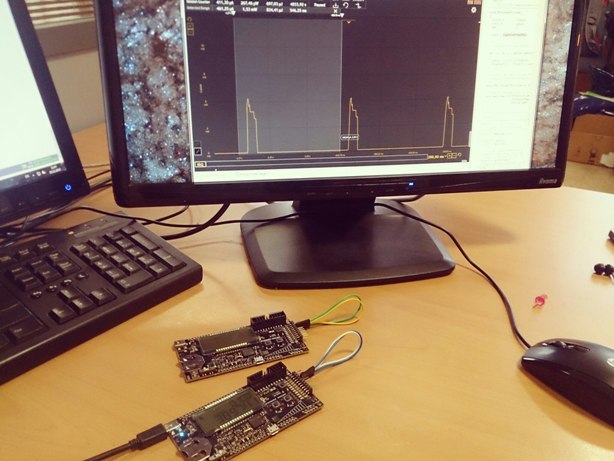
EFM32 Wonder Gecko SiLabs. . -.
EFM32WG — Cortex-M4F. EFM32, . Cortex-M3 Cortex-M4F.
:
EFM32WG-STK3800 — Cortex-M4F
EFM32GG-STK3700 — Cortex-M3
.

Simplicity Studio. SiLabs- , , , , Silabs. — IDE, energy profiler, user guide .
. , , , 0,5 : 512 . ProcessFFT().
, . .
Simplicity Studio, Simplicity IDE, .
プログラムリスト
, — , Simplicity IDE, IAR, Keil .
/***************************************************************************//** * @file lightsensefft.c * @brief FFT transform example * @details * Use ADC in order to capture and analyse input from the * light sensor on the STK. Runs floating point FFT algorithm from the CMSIS * DSP Library, and estimate the frequency of the most luminous light source * using sinc interpolation. The main point with this example is to show the * use of the CMSIS DSP library and the floating point capability of the CPU. * * @par Usage * Connect the light sensor output to the ADC input by shorting pins * 15 and 14 on the EXP_HEADER of the STK. * Direct various light sources to the light sensor. Expect no specific * frequency from daylight or from a flashlight. Mains powered incandescent * bulbs should give twice the mains frequency. Using another STK running the * "blink" example modified to various blink rates is an excellent signal * source. The frequency bandwidth is approximately 10-500 Hz. * The frequency shows in the 4 digit numerical display upper right on * the LCD. The LCD also displays the number of CPU cycles used to do * the FFT transform. * * @author Silicon Labs * @version 1.04 ******************************************************************************* * @section License * <b>(C) Copyright 2014 Silicon Labs, http://www.silabs.com</b> ******************************************************************************* * * Permission is granted to anyone to use this software for any purpose, * including commercial applications, and to alter it and redistribute it * freely, subject to the following restrictions: * * 1. The origin of this software must not be misrepresented; you must not * claim that you wrote the original software. * 2. Altered source versions must be plainly marked as such, and must not be * misrepresented as being the original software. * 3. This notice may not be removed or altered from any source distribution. * * DISCLAIMER OF WARRANTY/LIMITATION OF REMEDIES: Silicon Labs has no * obligation to support this Software. Silicon Labs is providing the * Software "AS IS", with no express or implied warranties of any kind, * including, but not limited to, any implied warranties of merchantability * or fitness for any particular purpose or warranties against infringement * of any proprietary rights of a third party. * * Silicon Labs will not be liable for any consequential, incidental, or * special damages, or any other relief, or for any claim by any third party, * arising from your use of this Software. * ******************************************************************************/ #include "em_common.h" #include "em_emu.h" #include "em_cmu.h" #include "em_chip.h" #include "em_adc.h" #include "em_gpio.h" #include "em_rtc.h" #include "em_acmp.h" #include "em_lesense.h" #include "segmentlcd.h" #include "arm_math.h" #include "math.h" /** * Number of samples processed at a time. This number has to be equal to one * of the accepted input sizes of the rfft transform of the CMSIS DSP library. * Increasing it gives better resolution in the frequency, but also a longer * sampling time. */ #define BUFFER_SAMPLES 512 /** (Approximate) sample rate used for sampling data. */ #define SAMPLE_RATE (1024) /** The GPIO pin used to power the light sensor. */ #define EXCITE_PIN gpioPortD,6 /* Default configuration for alternate excitation channel. */ #define LESENSE_LIGHTSENSE_ALTEX_DIS_CH_CONF \ { \ false, /* Alternate excitation enabled.*/ \ lesenseAltExPinIdleDis, /* Alternate excitation pin is disabled in idle. */ \ false /* Excite only for corresponding channel. */ \ } /* ACMP */ #define ACMP_NEG_REF acmpChannelVDD #define ACMP_THRESHOLD 0x38 /* Reference value for the lightsensor. * Value works well in office light * conditions. Might need adjustment * for other conditions. */ /* LESENSE Pin config */ #define LIGHTSENSE_CH 6 #define LIGHTSENSE_EXCITE_PORT gpioPortD #define LIGHTSENSE_EXCITE_PIN 6 #define LIGHTSENSE_SENSOR_PORT gpioPortC #define LIGHTSENSE_SENSOR_PIN 6 #define LCSENSE_SCAN_FREQ 5 #define LIGHTSENSE_INTERRUPT LESENSE_IF_CH6 /** Buffer of uint16_t sample values ready to be FFT-ed. */ static uint16_t lightToFFTBuffer[BUFFER_SAMPLES]; /** Buffer of float samples ready for FFT. */ static float32_t floatBuf[BUFFER_SAMPLES]; /** Complex (interleaved) output from FFT. */ static float32_t fftOutputComplex[BUFFER_SAMPLES * 2]; /** Magnitude of complex numbers in FFT output. */ static float32_t fftOutputMag[BUFFER_SAMPLES]; /** Flag used to indicate whether data is ready for processing */ static volatile bool dataReadyForFFT; /** Indicate whether we are currently processing data through FFT */ static volatile bool processingFFT; /** Instance structures for float32_t RFFT */ static arm_rfft_instance_f32 rfft_instance; /** Instance structure for float32_t CFFT used by the RFFT */ static arm_cfft_radix4_instance_f32 cfft_instance; /**************************************************************************//** * Interrupt handlers prototypes *****************************************************************************/ void LESENSE_IRQHandler(void); /**************************************************************************//** * Functions prototypes *****************************************************************************/ void setupCMU(void); void setupACMP(void); void setupLESENSE(void); /**************************************************************************//** * @brief LESENSE_IRQHandler * Interrupt Service Routine for LESENSE Interrupt Line *****************************************************************************/ void LESENSE_IRQHandler(void) { /* Clear interrupt flag */ LESENSE_IntClear(LIGHTSENSE_INTERRUPT); } /***************************************************************************//** * @brief Enables LFACLK and selects osc as clock source for RTC ******************************************************************************/ void RTC_Setup(CMU_Select_TypeDef osc) { RTC_Init_TypeDef init; /* Ensure LE modules are accessible */ CMU_ClockEnable(cmuClock_CORELE, true); /* Enable osc as LFACLK in CMU (will also enable oscillator if not enabled) */ CMU_ClockSelectSet(cmuClock_LFA, osc); /* Division prescaler to decrease consumption. */ CMU_ClockDivSet(cmuClock_RTC, cmuClkDiv_32); /* Enable clock to RTC module */ CMU_ClockEnable(cmuClock_RTC, true); init.enable = false; init.debugRun = false; init.comp0Top = true; /* Count only to top before wrapping */ RTC_Init(&init); /* RTC clock divider is 32 which gives 1024 ticks per second. */ RTC_CompareSet(0, ((1024 * SAMPLE_RATE) / 1000000)-1); /* Enable interrupt generation from RTC0, needed for WFE (wait for event). */ /* Notice that enabling the interrupt in the NVIC is not needed. */ RTC_IntEnable(RTC_IF_COMP0); } /**************************************************************************//** * @brief Enable clocks for all the peripherals to be used *****************************************************************************/ void setupCMU(void) { /* Ensure core frequency has been updated */ SystemCoreClockUpdate(); /* Set the clock frequency to 11MHz so the ADC can run on the undivided HFCLK */ CMU_HFRCOBandSet(cmuHFRCOBand_11MHz); /* ACMP */ CMU_ClockEnable(cmuClock_ACMP0, true); /* GPIO */ CMU_ClockEnable(cmuClock_GPIO, true); /* ADC */ CMU_ClockEnable(cmuClock_ADC0, true); /* Low energy peripherals * LESENSE * LFRCO clock must be enables prior to enabling * clock for the low energy peripherals */ CMU_ClockSelectSet(cmuClock_LFA, cmuSelect_LFRCO); CMU_ClockEnable(cmuClock_CORELE, true); CMU_ClockEnable(cmuClock_LESENSE, true); /* RTC */ CMU_ClockEnable(cmuClock_RTC, true); /* Disable clock source for LFB clock. */ CMU_ClockSelectSet(cmuClock_LFB, cmuSelect_Disabled); } /**************************************************************************//** * @brief Sets up the ACMP *****************************************************************************/ void setupACMP(void) { /* Configuration structure for ACMP */ static const ACMP_Init_TypeDef acmpInit = { .fullBias = false, /* The lightsensor is slow acting, */ .halfBias = true, /* comparator bias current can be set to lowest setting.*/ .biasProg = 0x0, /* Analog comparator will still be fast enough */ .interruptOnFallingEdge = false, /* No comparator interrupt, lesense will issue interrupts. */ .interruptOnRisingEdge = false, .warmTime = acmpWarmTime512, /* Not applicable, lesense controls this. */ .hysteresisLevel = acmpHysteresisLevel5, /* Some hysteresis will prevent excessive toggling. */ .inactiveValue = false, /* Not applicable, lesense controls this. */ .lowPowerReferenceEnabled = false, /* Can be enabled for even lower power. */ .vddLevel = 0x00, /* Not applicable, lesense controls this through .acmpThres value. */ .enable = false /* Not applicable, lesense controls this. */ }; /* Initialize ACMP */ ACMP_Init(ACMP0, &acmpInit); /* Disable ACMP0 out to a pin. */ ACMP_GPIOSetup(ACMP0, 0, false, false); /* Set up ACMP negSel to VDD, posSel is controlled by LESENSE. */ ACMP_ChannelSet(ACMP0, acmpChannelVDD, acmpChannel0); /* LESENSE controls ACMP thus ACMP_Enable(ACMP0) should NOT be called in order * to ensure lower current consumption. */ } /**************************************************************************//** * @brief Sets up the LESENSE *****************************************************************************/ void setupLESENSE(void) { /* LESENSE configuration structure */ static const LESENSE_Init_TypeDef initLesense = { .coreCtrl = { /* LESENSE configured for periodic scan. */ .scanStart = lesenseScanStartPeriodic, .prsSel = lesensePRSCh0, .scanConfSel = lesenseScanConfDirMap, .invACMP0 = false, .invACMP1 = false, .dualSample = false, .storeScanRes = false, .bufOverWr = true, .bufTrigLevel = lesenseBufTrigHalf, .wakeupOnDMA = lesenseDMAWakeUpDisable, .biasMode = lesenseBiasModeDutyCycle, /* Lesense should duty cycle comparator and related references etc. */ .debugRun = false }, .timeCtrl = { .startDelay = 0 /* No start delay needed for this application. */ }, .perCtrl = { /* DAC is not needed for this application. */ .dacCh0Data = lesenseDACIfData, .dacCh0ConvMode = lesenseDACConvModeDisable, .dacCh0OutMode = lesenseDACOutModeDisable, .dacCh1Data = lesenseDACIfData, .dacCh1ConvMode = lesenseDACConvModeDisable, .dacCh1OutMode = lesenseDACOutModeDisable, .dacPresc = 0, .dacRef = lesenseDACRefBandGap, .acmp0Mode = lesenseACMPModeMuxThres, /* Allow LESENSE to control ACMP mux and reference threshold. */ .acmp1Mode = lesenseACMPModeMuxThres, .warmupMode = lesenseWarmupModeNormal /* Normal mode means LESENSE is allowed to dutycycle comparator and reference. */ }, .decCtrl = { /* Decoder or statemachine not used in this code example. */ .decInput = lesenseDecInputSensorSt, .initState = 0, .chkState = false, .intMap = true, .hystPRS0 = false, .hystPRS1 = false, .hystPRS2 = false, .hystIRQ = false, .prsCount = true, .prsChSel0 = lesensePRSCh0, .prsChSel1 = lesensePRSCh1, .prsChSel2 = lesensePRSCh2, .prsChSel3 = lesensePRSCh3 } }; /* Channel configuration */ /* Only one channel is configured for the lightsense application. */ static const LESENSE_ChDesc_TypeDef initLesenseCh = { .enaScanCh = true, .enaPin = false, /* Pin is input, no enabling needed. Separate pin is exciting the sensor. */ .enaInt = true, /* Enable interrupt for this channel. */ .chPinExMode = lesenseChPinExHigh, /* Excite by pullin pin high. */ .chPinIdleMode = lesenseChPinIdleDis, /* During Idle, excite pin should be disabled (tri-stated). */ .useAltEx = true, /* Use alternate excite pin. */ .shiftRes = false, /* Not applicable, only for decoder operation. */ .invRes = false, /* No need to invert result. */ .storeCntRes = true, /* Not applicable, don't care really. */ .exClk = lesenseClkLF, /* Using low frequency clock for timing the excitation. */ .sampleClk = lesenseClkLF, /* Using low frequency clock for timing the sample instant. */ .exTime = 0x01, /* 1 LFclk cycle is enough excitation time, this depends on response time of light sensor. */ .sampleDelay = 0x01, /* Sampling should happen when excitation ends, it it happens earlier, excitation time might as well be reduced. */ .measDelay = 0x00, /* Not used here, basically only used for applications which uses the counting feature. */ .acmpThres = ACMP_THRESHOLD, /* This is the analog comparator threshold setting, determines when the acmp triggers. */ .sampleMode = lesenseSampleModeACMP, /* Sampling acmp, not counting. */ .intMode = lesenseSetIntLevel, /* Interrupt when voltage goes above threshold. */ .cntThres = 0x0000, /* Not applicable. */ .compMode = lesenseCompModeLess /* Not applicable. */ }; /* Alternate excitation channels configuration. */ /* The lightsensor is excited by alternate excite channel 0. */ static const LESENSE_ConfAltEx_TypeDef initAltEx = { .altExMap = lesenseAltExMapALTEX, .AltEx[0] = { .enablePin = true, .idleConf = lesenseAltExPinIdleDis, .alwaysEx = true }, .AltEx[1] = LESENSE_LIGHTSENSE_ALTEX_DIS_CH_CONF, .AltEx[2] = LESENSE_LIGHTSENSE_ALTEX_DIS_CH_CONF, .AltEx[3] = LESENSE_LIGHTSENSE_ALTEX_DIS_CH_CONF, .AltEx[4] = LESENSE_LIGHTSENSE_ALTEX_DIS_CH_CONF, .AltEx[5] = LESENSE_LIGHTSENSE_ALTEX_DIS_CH_CONF, .AltEx[6] = LESENSE_LIGHTSENSE_ALTEX_DIS_CH_CONF, .AltEx[7] = LESENSE_LIGHTSENSE_ALTEX_DIS_CH_CONF }; /* Initialize LESENSE interface _with_ RESET. */ LESENSE_Init(&initLesense, true); /* Configure LESENSE channel */ LESENSE_ChannelConfig(&initLesenseCh, LIGHTSENSE_CH); /* Configure alternate excitation channels */ LESENSE_AltExConfig(&initAltEx); /* Set scan frequency */ LESENSE_ScanFreqSet(0, LCSENSE_SCAN_FREQ); /* Set clock divisor for LF clock. */ LESENSE_ClkDivSet(lesenseClkLF, lesenseClkDiv_2); } /**************************************************************************//** * @brief Sets up the GPIO *****************************************************************************/ void setupGPIO(void) { /* Configure the drive strength of the ports for the light sensor. */ GPIO_DriveModeSet(LIGHTSENSE_EXCITE_PORT, gpioDriveModeStandard); GPIO_DriveModeSet(LIGHTSENSE_SENSOR_PORT, gpioDriveModeStandard); /* Initialize the 2 GPIO pins of the light sensor setup. */ GPIO_PinModeSet(LIGHTSENSE_EXCITE_PORT, LIGHTSENSE_EXCITE_PIN, gpioModePushPull, 0); GPIO_PinModeSet(LIGHTSENSE_SENSOR_PORT, LIGHTSENSE_SENSOR_PIN, gpioModeDisabled, 0); } /**************************************************************************//** * @brief Configure ADC for 12 bit mode, sample channel 0 with Vdd as reference * and use shortest acquisition time. *****************************************************************************/ static void ADC_Config(void) { CMU_ClockEnable(cmuClock_ADC0, true); ADC_Init_TypeDef init = ADC_INIT_DEFAULT; ADC_InitSingle_TypeDef singleInit = ADC_INITSINGLE_DEFAULT; /* Init common settings for both single conversion and scan mode- */ /* Set timebase to 10, this gives 11 cycles which equals 1us at 11 MHz. */ init.timebase = 10; /* Set ADC clock prescaler to 0, we are using 11MHz HFRCO, which results in HFPERCLK < 13MHz- */ init.prescale = 0; ADC_Init(ADC0, &init); /* Init for single conversion use, measure channel 0 with Vdd as reference. */ /* Using Vdd as reference removes the 5us warmup time for the bandgap reference. */ singleInit.reference = adcRefVDD; singleInit.input = adcSingleInpCh5; /* Resolution can be set lower for even more energy efficient operation. */ singleInit.resolution = adcRes8Bit; /* Assuming we are mesuring a low impedance source we can safely use the shortest */ /* acquisition time. */ singleInit.acqTime = adcAcqTime1; ADC_InitSingle(ADC0, &singleInit); /* Enable ADC Interrupt when Single Conversion Complete. */ /* This is necessary for WFE (wait for event) to work. */ /* Notice that enabling the interrupt in the NVIC is not needed. */ ADC0->IEN = ADC_IEN_SINGLE; } /**************************************************************************//** * @brief A separate function for taking all the samples is preferred since * the whole idea is to stay in EM2 between samples. If other code is added, * it might be more energy efficient to configure the ADC to use DMA while * the cpu can do other work. *****************************************************************************/ void doAdcSampling(uint16_t* buffer) { uint16_t sample_count = 0; /* Enable RTC, this can be enabled all the time as well if needed. */ RTC_Enable(true); while(sample_count < BUFFER_SAMPLES) { /* Enable deep sleep to enter EM2 between samples. */ SCB->SCR = SCB_SCR_SEVONPEND_Msk | SCB_SCR_SLEEPDEEP_Msk; /* Go to sleep while waiting for RTC event (set by RTC_IRQ pending bit) */ /* Since IRQ is not enabled in the NVIC, no ISR will be entered */ __WFE(); /* Start ADC conversion as soon as we wake up. */ ADC_Start(ADC0, adcStartSingle); /* Clear the interrupt flag */ RTC_IntClear(RTC_IF_COMP0); /* Clear pending RTC IRQ */ NVIC_ClearPendingIRQ(RTC_IRQn); /* Wait while conversion is active in EM1, should be almost finished since it */ /* takes 13 cycles + warmup (1us), and it was started a while ago. */ /* Disable deep sleep so we wait in EM1 for conversion to finish. */ SCB->SCR = SCB_SCR_SEVONPEND_Msk; __WFE(); /* Clear the interrupt flag */ ADC_IntClear(ADC0, ADC_IF_SINGLE); /* Clear pending IRQ */ NVIC_ClearPendingIRQ(ADC0_IRQn); /* Get ADC result */ buffer[sample_count++] = ADC_DataSingleGet(ADC0); } RTC_Enable(false); } /***************************************************************************//** * @brief * Process the sampled data through FFT. *******************************************************************************/ void ProcessFFT(void) { uint16_t *inBuf; int32_t value; int i; inBuf = lightToFFTBuffer; /* * Convert to float values. */ for (i = 0; i < BUFFER_SAMPLES; ++i) { value = (int32_t)*inBuf++; floatBuf[i] = (float32_t)value; } /* Process the data through the RFFT module, resulting complex output is * stored in fftOutputComplex */ arm_rfft_f32(&rfft_instance, floatBuf, fftOutputComplex); /* Compute the magnitude of all the resulting complex numbers */ arm_cmplx_mag_f32(fftOutputComplex, fftOutputMag, BUFFER_SAMPLES); } /***************************************************************************//** * @brief * Find the maximal bin and estimate the frequency using sinc interpolation. * @return * Frequency of maximal peak *******************************************************************************/ float32_t GetFreq(void) { float32_t maxVal; uint32_t maxIndex; /* Real and imag components of maximal bin and bins on each side */ float32_t rz_p, iz_p, rz_n, iz_n, rz_0, iz_0; /* Small correction to the "index" of the maximal bin */ float32_t deltaIndex; /* Real and imag components of the intermediate result */ float32_t a, b, c, d; #define START_INDEX 4 /* Find the biggest bin, disregarding the first bins because of DC offset and * low frequency noise. */ arm_max_f32(&fftOutputMag[START_INDEX], BUFFER_SAMPLES / 2 - START_INDEX, &maxVal, &maxIndex); maxIndex += START_INDEX; /* Perform sinc() interpolation using the two bins on each side of the * maximal bin. For more information see page 113 of * http://tmo.jpl.nasa.gov/progress_report/42-118/118I.pdf */ /* z_{peak} */ rz_0 = fftOutputComplex[maxIndex * 2]; iz_0 = fftOutputComplex[maxIndex * 2 + 1]; /* z_{peak+1} */ rz_p = fftOutputComplex[maxIndex * 2 + 2]; iz_p = fftOutputComplex[maxIndex * 2 + 2 + 1]; /* z_{peak-1} */ rz_n = fftOutputComplex[maxIndex * 2 - 2]; iz_n = fftOutputComplex[maxIndex * 2 - 2 + 1]; /* z_{peak+1} - z_{peak-1} */ a = rz_p - rz_n; b = iz_p - iz_n; /* z_{peak+1} + z_{peak-1} - 2*z_{peak} */ c = rz_p + rz_n - (float32_t)2.0 * rz_0; d = iz_p + iz_n - (float32_t)2.0 * iz_0; /* Re (z_{peak+1} - z_{peak-1}) / (z_{peak+1} + z_{peak-1} - 2*z_{peak}) */ deltaIndex = (a*c + b*d) / (c*c + d*d); return ((float32_t)maxIndex + deltaIndex) * (float32_t)SAMPLE_RATE / (float32_t)BUFFER_SAMPLES; } /***************************************************************************//** * @brief * Main function. Setup ADC, FFT, clocks, PRS, DMA, Timer, * and process FFT forever. *******************************************************************************/ int main(void) { uint32_t time; arm_status status; /* Chip errata */ CHIP_Init(); /* Enable clocks for used peripherals */ setupCMU(); /* Setup the ACMP */ setupACMP(); /* Setup the GPIO */ setupGPIO(); /* setup lesense */ setupLESENSE(); /* Enable LCD without voltage boost */ SegmentLCD_Init(false); SegmentLCD_Symbol(LCD_SYMBOL_GECKO, 1); SegmentLCD_Symbol(LCD_SYMBOL_EFM32, 1); /* Initialize the CFFT/CIFFT module */ status = arm_rfft_init_f32(&rfft_instance, &cfft_instance, BUFFER_SAMPLES, 0, /* forward transform */ 1); /* normal, not bitreversed, order */ if (status != ARM_MATH_SUCCESS) { /* Error initializing RFFT module. */ SegmentLCD_Write(" Error "); while (1) ; } /* Configure RTC to use LFXO as clock source */ RTC_Setup(cmuSelect_LFXO); /* Configure ADC */ ADC_Config(); /* Enable DWT */ CoreDebug->DEMCR |= CoreDebug_DEMCR_TRCENA_Msk; /* Make sure CYCCNT is running */ DWT->CTRL |= 1; while (1) { /* Power the light sensor with GPIO. */ GPIO_PinModeSet( EXCITE_PIN, gpioModePushPull, 1); /* Do sampling. */ doAdcSampling(lightToFFTBuffer); /* Power off the light sensor. */ GPIO_PinModeSet( EXCITE_PIN, gpioModeDisabled, 0); /* Do FFT, measure number of cpu cycles used. */ time = DWT->CYCCNT; ProcessFFT(); time = DWT->CYCCNT - time; /* Display dominant frequency. */ SegmentLCD_Number( (int)GetFreq() ); /* Display cpu cycle count used to do FFT. */ SegmentLCD_LowerNumber( (int)time ); /* Check last ADC value to determine if lightlevel is too low. */ /* Go to sleep with lesense enabled if ADC reading is below 10. */ if(lightToFFTBuffer[BUFFER_SAMPLES-1] < 10) { /* Write to LCD that lightlevel is too low. */ SegmentLCD_NumberOff(); SegmentLCD_Write("DARK"); /* Set gpio in pushpull for lesense operation. */ GPIO_PinModeSet(LIGHTSENSE_EXCITE_PORT, LIGHTSENSE_EXCITE_PIN, gpioModePushPull, 0); LESENSE->ROUTE = LESENSE_ROUTE_ALTEX0PEN; /* Start scan. */ LESENSE_ScanStart(); /* Enable deep sleep to enter EM2. */ SCB->SCR = SCB_SCR_SEVONPEND_Msk | SCB_SCR_SLEEPDEEP_Msk; /* Go to sleep while waiting for LESENSE event */ /* Since IRQ is not enabled in the NVIC, no ISR will be entered */ __WFE(); /* Clear interrupt flag */ LESENSE_IntClear(LIGHTSENSE_INTERRUPT); /* Clear pending RTC IRQ */ NVIC_ClearPendingIRQ(LESENSE_IRQn); LESENSE_ScanStop(); LESENSE->ROUTE &= ~LESENSE_ROUTE_ALTEX0PEN; } } }
DBG, , ( light sensor), .
: . , — 100 ( 50 , « » , , .. ). «DARK», — «» .

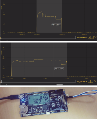
energy profiler , , .
EFM32WG-STK3800.
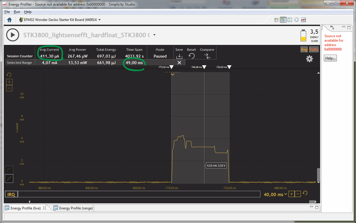
EFM32WG990F256 49 , — 411 . Cortex-M3, DSP- FPU- .
EFM32WG990F256 EFM32GG990F1024, 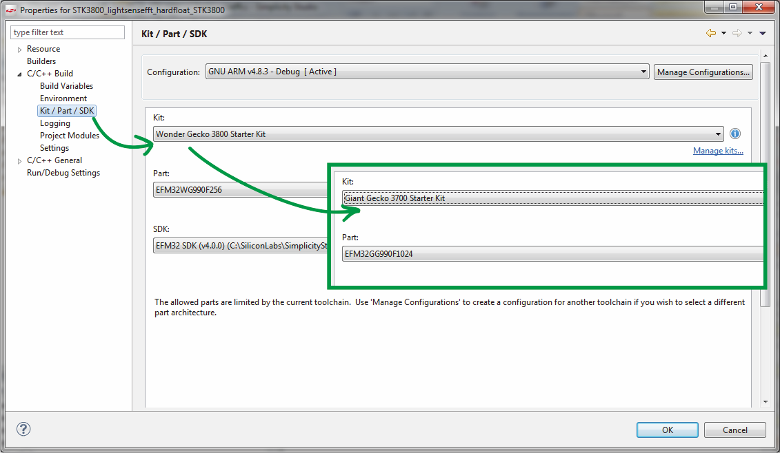
, cortex-m3 cortex-m4, 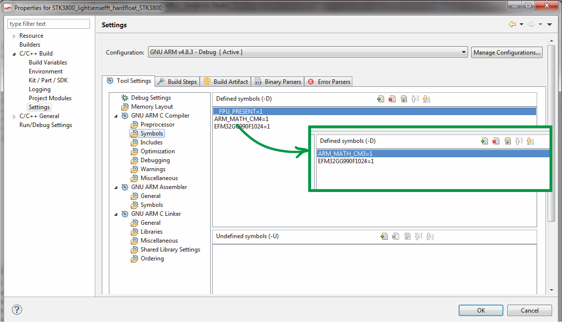
fpu. 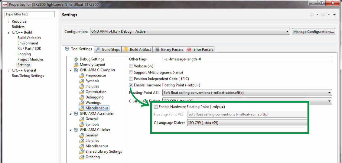
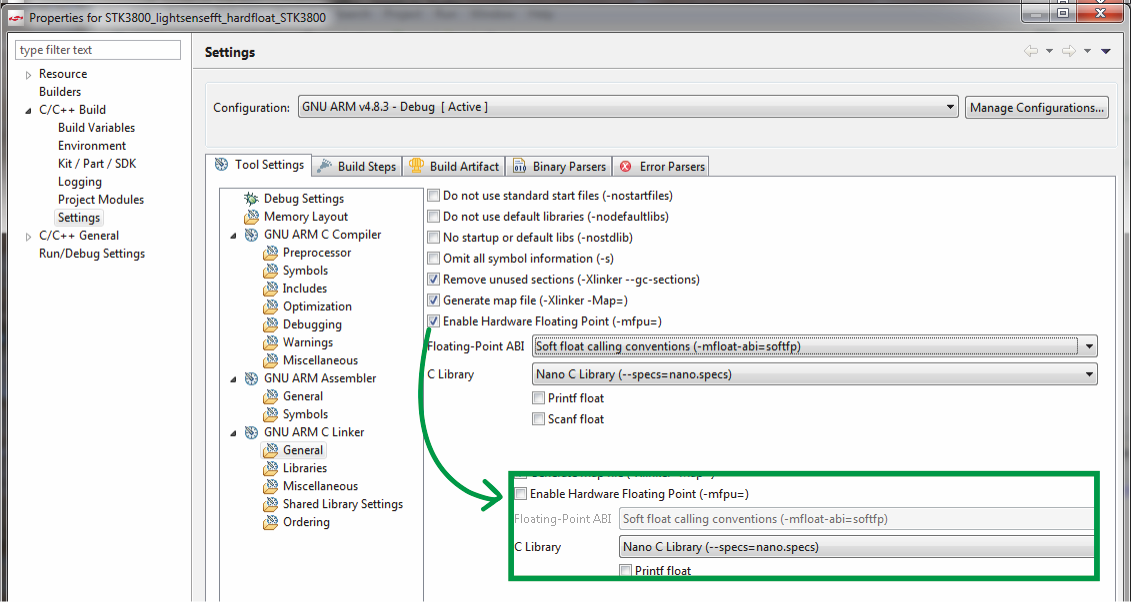
, IDE , , .
, .

: 48 , , .
, . «» . Cortex-M3 2.2 , .
, , Cortex-M3, , .
, .