特定の応用例に重点が置かれ、誰でもシミュレータまたは実際のハードウェアで実行できます。 このサンプルは、Modelsim SEを使用したザイリンクスISE環境での便利なシミュレーション用に作成されたもので、最小限の変更で本格的なIPコアに実装されています。
問題の声明
コアロジックの周波数と同期していない可能性がある、パルス信号の位相シフトを所定の値で実行します(パルスの持続時間は任意です)。 モジュール/デバイスを再起動またはシャットダウンせずにこれを行います。
ツール
バイナリコードの遅延コードが設定される8ポジションのDIPスイッチ(シフト値)。 ハードリセットまたはソフトリセット-初期リセット、デフォルトパラメータの設定。 基準周波数は100 MHz、つまり10 nsの最小オフセット時間です。
実装
インパルスを論理ユニットと呼びます-1。
一時停止、論理ゼロ-0。
コードはステートマシンとして実装されます。これは、段階的な構造と各ステージに明確な名前を付ける機能のおかげで、非常にシンプルで理解しやすいと思います。
コードに関するコメントに加えて、テストベンチシミュレーションファイルが含まれています。
ステートマシン図:
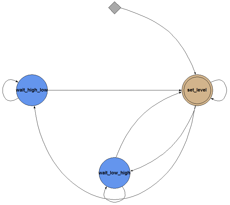
基本的なロジック。 コードは信号レベルの変化を監視し、その値が設定されたシフトと等しくなるとカウンターが開始し、円でモニターされているのと同じレベルが出力されます。
freq_shift_half_cycle.vhd
library ieee; use ieee.std_logic_1164.all; use ieee.numeric_std.all; use ieee.std_logic_arith.all; use ieee.std_logic_unsigned.all; entity freq_shift_half_cycle is Port ( Bus2IP_Clk : in STD_LOGIC; -- Bus2IP_Reset : in STD_LOGIC; -- Clk_in : in STD_LOGIC; -- Shift_reg : in STD_LOGIC_VECTOR (7 downto 0); -- Bus2IP_Clk counter_reg_test : out STD_LOGIC_VECTOR (7 downto 0); -- Clk_out : out STD_LOGIC -- ); end freq_shift_half_cycle; architecture Behavioral of freq_shift_half_cycle is type state_type is (set_level, wait_high_low, wait_low_high); -- signal current_stage : state_type; signal counter_shift : STD_LOGIC_VECTOR (7 downto 0); -- begin shift_fsm : process (Bus2IP_Reset, Bus2IP_Clk, Clk_in, Shift_reg) begin if Shift_reg = x"00" or Bus2IP_Reset = '1' then -- reset Clk_out <= Clk_in; counter_shift <= x"01"; counter_reg_test <= x"01"; -- current_stage <= set_level; elsif (Bus2IP_Clk'event and Bus2IP_Clk = '1') then case current_stage is when set_level => if counter_shift = Shift_reg then -- , 0 1 if Clk_in = '1' then Clk_out <= '1'; current_stage <= wait_high_low; else Clk_out <= '0'; current_stage <= wait_low_high; end if; counter_shift <= x"01"; counter_reg_test <= x"01"; -- elsif counter_shift < Shift_reg then counter_shift <= counter_shift + 1; counter_reg_test <= counter_shift + 1; -- current_stage <= set_level; end if; when wait_high_low => -- 1 0 set_level if Clk_in = '1' then current_stage <= wait_high_low; else current_stage <= set_level; end if; when wait_low_high => -- 0 1 set_level if Clk_in = '0' then current_stage <= wait_low_high; else current_stage <= set_level; end if; when others => current_stage <= set_level; end case; end if; end process shift_fsm; end Behavioral;
Modelsimのシミュレーションコード:
testbench_half_cycle.vhd
LIBRARY ieee; USE ieee.std_logic_1164.ALL; -- Uncomment the following library declaration if using -- arithmetic functions with Signed or Unsigned values --USE ieee.numeric_std.ALL; ENTITY testbench_half_cycle IS END testbench_half_cycle; ARCHITECTURE behavior OF testbench_half_cycle IS -- Component Declaration for the Unit Under Test (UUT) COMPONENT freq_shift_half_cycle PORT( Bus2IP_Clk : IN std_logic; Bus2IP_Reset : IN std_logic; Clk_in : IN std_logic; Shift_reg : IN std_logic_vector(7 downto 0); counter_reg_test : OUT std_logic_vector(7 downto 0); Clk_out : OUT std_logic ); END COMPONENT; --Inputs signal Bus2IP_Clk : std_logic := '0'; signal Bus2IP_Reset : std_logic := '0'; signal Clk_in : std_logic := '0'; signal Shift_reg : std_logic_vector(7 downto 0) := (others => '0'); --Outputs signal counter_reg_test : std_logic_vector(7 downto 0); signal Clk_out : std_logic; -- Clock period definitions constant Bus2IP_Clk_period : time := 10 ns; constant Clk_in_period : time := 100 ns; BEGIN -- Instantiate the Unit Under Test (UUT) uut: freq_shift_half_cycle PORT MAP ( Bus2IP_Clk => Bus2IP_Clk, Bus2IP_Reset => Bus2IP_Reset, Clk_in => Clk_in, Shift_reg => Shift_reg, counter_reg_test => counter_reg_test, Clk_out => Clk_out ); -- Clock process definitions Bus2IP_Clk_process :process begin Bus2IP_Clk <= '1'; wait for Bus2IP_Clk_period/2; Bus2IP_Clk <= '0'; wait for Bus2IP_Clk_period/2; end process; Clk_in_process :process begin Clk_in <= '1'; wait for Clk_in_period/2; Clk_in <= '0'; wait for Clk_in_period/2; -- wait for 1000 ns; end process; -- Stimulus process stim_proc: process begin -- hold reset state for 100 ns. Bus2IP_Reset <= '1'; wait for 500 ns; Bus2IP_Reset <= '0'; wait for 5000 ns; Shift_reg <= x"01"; -- wait for 5000 ns; Shift_reg <= x"00"; wait for 5000 ns; Shift_reg <= x"04"; wait for Bus2IP_Clk_period*10; -- insert stimulus here wait; end process; END;
経験豊富な電子技術者は、このコードの欠点に気付くことができます。 設定された遅延は以下を超えてはなりません。
-パルス持続時間、パルス持続時間が休止時間より短い場合。
-ポーズの継続時間がパルスの継続時間より短い場合、ポーズの継続時間。
つまり 位相シフトの大きさは、パルス信号の場合、0と1の両方で180°を超えてはなりません。
以下の図では、ロジックの動作が遅れている状態で、入力信号のリアルタイムで40 nsの位相シフトがどのように実行されるかを確認できます。

以下は、調整可能な信号と基準周波数が非同期の場合の状況のデモンストレーションです。
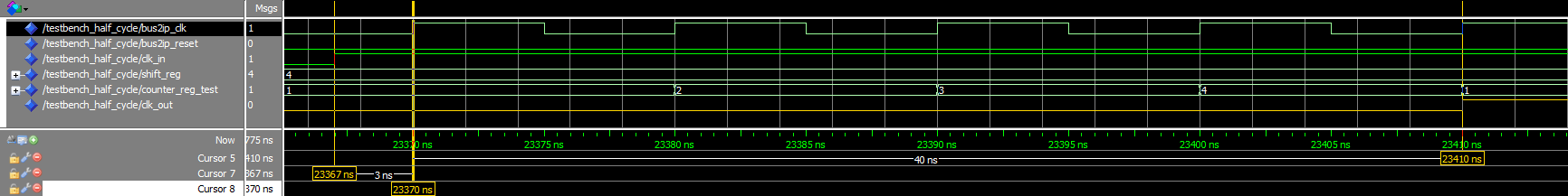
この状況を分析し、独自の結論を引き出すことをお勧めします。
次の記事では、このコードに新しい機能を追加することで、あなたのコメントとコメントを聞いてうれしいです。
ご清聴ありがとうございました。