約1年前、公式のArduino Starter Kitで遊んでいたときに、妻に「サーキットケーキ」、つまり吹き飛ばすことができるLEDキャンドルの付いたボードを渡すようになりました。 このタスクは、マイクロコントローラーのプログラミング方法とプログラムを問題に変換する方法を理解するための良い教育プロジェクトのように思えました(結局、私は比較的最近エレクトロニクスに関与し始め、学校でプログラミングを始めたので、教育に大きなギャップを感じました)。
このようなシンプルなデバイスをゼロから開発した経験を共有し、同時にそのスキームとプログラムをレイアウトして、自宅でプレイできるようにしたいと思います。
物語
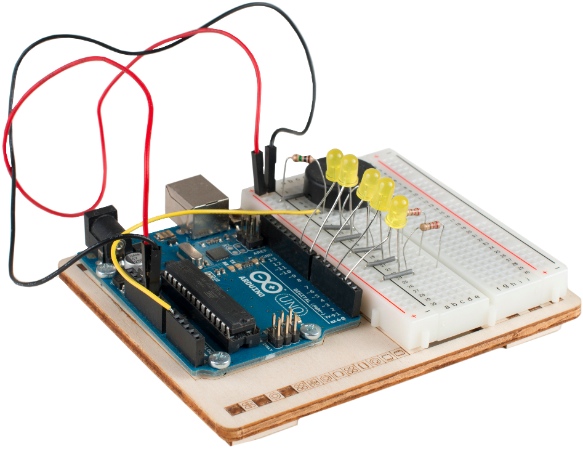
最初のプロトタイプは、 Arduino Unoで作成され、ろうそくを吹き消すための検出器として圧電素子が取り付けられました。

圧電素子の電圧を読み取ると、デバイスは読み取り値のわずかな変化を予期していました。 しかし、ADCの最大解像度でさえ、ろうそくが消え始めるように非常によく吹く必要がありました。 しかし、それらはうまくいきました。最初は、それぞれのろうそくに与えられたランダムな寿命に応じて、異なる周波数と位相で明滅し始め、次に順番に消えました。
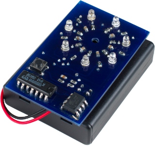
次のステップでは、ワイヤーを貼り付けたボードよりもケーキをエレガントにすることにしました。 また、ケーキが小さなマイクロコントローラーで動作することを妻に見せたかった。 インターネットのどこかで、 ArduinoをATTiny85コントローラーで実行できるという記事を見つけ、それを頭脳として使用することにしました。 問題は、このコントローラーにはろうそくとセンサーに使用できる汎用脚が5つしかないため、各LEDを別々の脚に置くと4つのろうそくしか使用できないことが判明したことです。 当時、私はチャーレプレックスについて知らなかったので、ろうそくをインバーターの遅延回路で複製することにしました。LEDが点滅すると、だれかが位相遅延で複製されていることに気付かないでしょう。 さらに、追加の要素は、キャンドルを配置するための円形パターンにうまく適合します。

電源として、4つのAAAバッテリーを使用しましたが、外観の簡潔さに違反しました。 さらに、私はより正直なろうそくとより高い感度が欲しかった。 ATTinyシリーズのマイクロコントローラーの仕様を調べてみたところ、11の一般的な汎用脚を持つATTiny84という素晴らしいアナログが見つかりました。 さらに、20倍の差動アンプを備えたADC入力を備えています! そこで、新しいプロトタイプが登場しました。

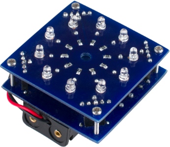
フロア間に2個のAAAバッテリーを入れたいと思っていましたが、ラックのサイズとピエゾ素子の計算を間違えました。これはボードに隣接してはならないため、バッテリーをボードの下に貼り付けなければなりませんでした。 信号の増幅により、ケーキの感度が非常に高くなり、ノイズが発生したため、アルゴリズムを変更する必要がありました。信号の標準偏差を測定し、この偏差が経験的に決定されたしきい値を超えたときにブローイングロジックをオンにしました。 プログラムは小さく、4 kB未満であることが判明したため、 ATTiny44を使用しました。
回路の電源と床の間の空きスペースが本当に好きではありませんでした。バッテリーの仕様を調べてみると、AAAAバッテリーがあることがわかりました。 それらは非常に小さく、数百ミリアンペアの電流を供給します。 購入するのは難しいですが、タイプ6LR61の 9ボルトのバッテリーを使用する場合は、6個のAAAAバッテリーで構成されています。
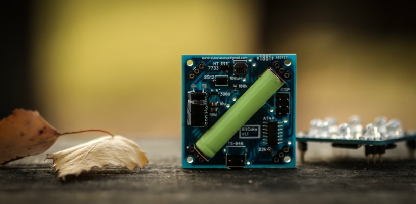
また、バッテリー電流を増やすことで供給電圧を+5 Vに上げる興味深いHT7750スイッチング電源マイクロサーキットを見つけ、対角線に1つのAAAAバッテリーが収まるサイズのケーキを作ることにしました。 次のプロトタイプが判明しました。

広角LEDを使用すると、ケーキの美観が向上するだけでなく、視野角も広がりました。 中国でボードを注文しました。これにより、完成したデバイスの品質が向上しました。 しかし、私が予想していなかったのは、吹くときのノイズの急激な増加でした。 実際には、スイッチング電源自体にノイズが多く、ここでは、異なる数のLEDがオンのときの出力電圧の電流依存性もあります。 古いアルゴリズムは機能しなくなったため、圧電センサーからコンピューターへの読み取り値を読み取り、信号の振幅周波数特性を分析するという、より徹底的なタスクにアプローチする必要がありました。 私は、1分間の沈黙、1分間の吹き飛ばし、そして1分間の身体に対する摩擦音を記録しました。 圧電素子の共振は約1 kHzであり、ろうそくが吹き消されていることが確実に判断できます。
そのため、ろうそくを吹き消す瞬間を判断するために、周波数1 kHzのハニングウィンドウを使用した高速フーリエ変換を検討し始めました。 ATTiny44には乗算コマンドが組み込まれておらず、メモリが非常に限られているため(256バイトのRAM、プログラムごとに4 kB)、すべての乗算をシフトと加算に置き換える必要があり、一般にすべてが適合するようにプログラムを最適化することが不可欠でした。 プログラム変更の結果、ケーキは他のすべてのプロトタイプの感度を上回りました。 その後、信号経路内の不要な成分を除去し始めました。これは単純にハイパスフィルターと見なされ、ケーキの応答性はさらに向上しました。 HT7750をHT7733に交換します 。 出力を+5 Vから+3.3 Vに置き換えると、バッテリーをより経済的に使用できます。
最後に私を混乱させたのは、オフモードのパワーチップが約17 µAを消費したことで、これは1年でバッテリーが空になったことを意味します。 しかし、このチップにはイネーブル入力を備えたSOT-25パッケージの一実施形態があり、リセットボタンを押すとチップの解像度入力で高レベルを供給するためにコンデンサを充電し、その後ゆっくり放電する小さなスイッチング回路を構成したことを思い出しました10メガオームの抵抗を介して3分間。 このタイムアウト後、ケーキはオフになり、1μA未満の消費を開始します。これは、バッテリーの自己放電電流に匹敵します。

回路図

HT7733は、入力電圧を+3.3 Vに上げるスイッチング電源です。直径20 mmのピエゾ素子は、マイクロコントローラーの差動ADCに20倍のゲインで接続されます。 各LEDは、マイクロコントローラーの一方の脚に接続されています。
RESETを押すと、トランジスタが開き、10μFのコンデンサが充電され、パワーチップの分解能入力に高レベルが適用されます。 チップはオンになり、3分間+3.3 Vの出力を開始しますが、10 uFのコンデンサは10メガオームの抵抗を通して放電されます。
プログラム
Arduino IDE用のC ++プログラム
///////////////////////////////////////////////////////////////////////////////////////////////// // BitCake v1.1.1 / November 8, 2014 // by Maksym Ganenko <buratin.barabanus at Google Mail> ///////////////////////////////////////////////////////////////////////////////////////////////// #include <avr/interrupt.h> #include <avr/pgmspace.h> #include <avr/power.h> #include <avr/sleep.h> #include <time.h> #include <util/delay.h> ///////////////////////////////////////////////////////////////////////////////////////////////// // set fixed delta loop time in milliseconds // 0 to use internal timer const uint8_t DELTA_LOOP_TIME_MS = 14; // amplify intermediate values to get better calculation accuracy const uint8_t SAMPLES_GAIN_ORDER = 5; // x32 const uint8_t RESULT_GAIN_ORDER = 2; // x4 // LEDs encoded by ports ID const prog_int8_t LEDS[] PROGMEM = { 0xA6, 0xA7, 0xB2, 0xB1, 0xB0, 0xA2, 0xA3, 0xA4, 0xA5 }; const uint8_t LEDS_NUM = sizeof(LEDS) / sizeof(LEDS[0]); // ADMUX register code for ADC const uint8_t PIEZO_ADMUX = 0b10101001; // Vref = 1.1V, (A1 - A0) x 20 // MCU prescaler const uint8_t MCU_PRESCALER = 0b000; // 1 => 8 Mhz CPU clock // ADC prescaler const uint8_t ADC_PRESCALER = 0b100; // 16 => 512 kHz ADC clock => 38.5k reads per sec // number of piezo reads to average per sample (for noise reduction) const uint8_t SUBSAMPLE_BUF_ORDER = 4; // => 16 const uint8_t SUBSAMPLE_BUF_SIZE = (1 << SUBSAMPLE_BUF_ORDER); // FFT samples number - can't be changed without changing FFT calculation code const uint8_t SAMPLE_BUF_ORDER = 5; // => 32 const uint8_t SAMPLE_BUF_SIZE = (1 << SAMPLE_BUF_ORDER); // FFT signal threshold to activate blowing logic // this value defines the sensitivity of device // depends on electronic components noise const uint8_t BLOWING_THRESHOLD = 3; // timeouts in milliseconds const uint32_t SETUP_TIME_MS = 750; // timeout before activating of cake logic const uint32_t DELAY_BLOWING_MS = 0; // delay LEDs flickering when blowing detected const uint32_t PROLONG_BLOWING_MS = 150; // prolong blowing logic when no blowing detected const uint32_t NO_ACTIVITY_MS = 60000; // turn off cake if no blowing detected const uint32_t TIME_LIMIT_MS = 150000; // time limit for cake to work // LEDs blinking periods when blowing logic is activated const uint8_t LEDS_PERIOD_MIN_MS = 100; const uint8_t LEDS_PERIOD_MAX_MS = 150; // LEDs time-to-live timeouts const uint16_t LEDS_TTL_MIN_MS = 200; const uint16_t LEDS_TTL_MAX_MS = 1000; ///////////////////////////////////////////////////////////////////////////////////////////////// volatile uint8_t samplePos = SAMPLE_BUF_SIZE; // FFT10 specific accumulators int16_t sampleAccA [5]; int16_t sampleAccB [5]; // LEDs state variables uint16_t ledsActivity; uint8_t ledsPeriod [LEDS_NUM]; uint8_t ledsPhase [LEDS_NUM]; uint8_t ledsTTL [LEDS_NUM]; // blowing logic state uint8_t blowing = false; uint32_t lastBlowingTime = 0; int16_t totalBlowingTime = 0; uint32_t globalTime = 0; uint32_t lastLoopTime; uint32_t setupPhaseTime; // for compatibility with other Atmel MCUs uint8_t portA, portB, portC, portD; ///////////////////////////////////////////////////////////////////////////////////////////////// // fast distance approximation uint32_t approxDist(int32_t dx, int32_t dy) { uint32_t min, max; if (dx < 0) dx = -dx; if (dy < 0) dy = -dy; if (dx < dy) { min = dx; max = dy; } else { min = dy; max = dx; } // coefficients equivalent to (123/128 * max) and (51/128 * min) return (((max << 8) + (max << 3) - (max << 4) - (max << 1) + (min << 7) - (min << 5) + (min << 3) - (min << 1)) >> 8); } const uint8_t FFT_DIVIDER_ORDER = 8; // => 256 // approximate multiplication int32_t mul256(int32_t x) { return x << 8; } int32_t mul240(int32_t x) { return (x << 8) - (x << 4); } int32_t mul208(int32_t x) { return (x << 7) + (x << 6) + (x << 4); } int32_t mul176(int32_t x) { return (x << 7) + (x << 5) + (x << 4); } int32_t mul144(int32_t x) { return (x << 7) + (x << 4); } int32_t mul96(int32_t x) { return (x << 6) + (x << 5); } int32_t mul48(int32_t x) { return (x << 5) + (x << 4); } typedef int32_t (*fmul32)(int32_t); const fmul32 fmulVec[4] = { mul96, mul176, mul240, mul256 }; // calculate FFT[10] for 32 samples uint8_t fft10() { int32_t a = 0; for (uint8_t i = 0; i < 4; ++i) { a += fmulVec[i](sampleAccA[i + 1]); } int32_t b = 0; for (uint8_t i = 0; i < 4; ++i) { b += fmulVec[i](sampleAccB[i + 1]); } uint32_t result = approxDist(a << RESULT_GAIN_ORDER, b << RESULT_GAIN_ORDER); result >>= FFT_DIVIDER_ORDER; if (result > 0xff) return 0xff; return result; } ///////////////////////////////////////////////////////////////////////////////////////////////// // fft10 specific coefficients const prog_int8_t sampleAccDestA[SAMPLE_BUF_SIZE / 2] PROGMEM = { +4, -1, -2, +3, +0, -3, +2, +1, -4, +1, +2, -3, +0, +3, -2, -1 }; const prog_int8_t sampleAccDestB[SAMPLE_BUF_SIZE / 2] PROGMEM = { +0, +3, -2, -1, +4, -1, -2, +3, +0, -3, +2, +1, -4, +1, +2, -3 }; const uint8_t HANNING_DIVIDER_ORDER = 6; // => 64 // hanning window coefficients int16_t mul0(int16_t x) { return 0; } int16_t mul1(int16_t x) { return x; } int16_t mul3(int16_t x) { return (x << 2) - x; } int16_t mul6(int16_t x) { return (x << 3) - (x << 1); } int16_t mul10(int16_t x) { return (x << 3) + (x << 1); } int16_t mul15(int16_t x) { return (x << 4) - x; } int16_t mul21(int16_t x) { return (x << 4) + (x << 2) + x; } int16_t mul27(int16_t x) { return (x << 5) - (x << 2) - x; } int16_t mul34(int16_t x) { return (x << 5) + (x << 2); } int16_t mul40(int16_t x) { return (x << 5) + (x << 3); } int16_t mul46(int16_t x) { return (x << 5) + (x << 4) - (x << 2); } int16_t mul52(int16_t x) { return (x << 6) - (x << 3) - (x << 2); } int16_t mul56(int16_t x) { return (x << 6) - (x << 3); } int16_t mul60(int16_t x) { return (x << 6) - (x << 2); } int16_t mul63(int16_t x) { return (x << 6) - x; } int16_t mul64(int16_t x) { return (x << 6); } // hanning window coefficients typedef int16_t (*fmul16)(int16_t); const fmul16 hanningVec[] = { mul0, mul1, mul3, mul6, mul10, mul15, mul21, mul27, mul34, mul40, mul46, mul52, mul56, mul60, mul63, mul64 }; // ADC interrup routine // we average SUBSAMPLE_BUF_SIZE reads from ADC to reduce noise // and apply the calculated value on fft10 specific accumulators ISR(ADC_vect) { static uint8_t subsampleCtr = 0; static int16_t subsampleSum = 0; // read ADC uint8_t low = ADCL, high = ADCH; int16_t subsample = (high << 8) | low; if (samplePos < SAMPLE_BUF_SIZE) { subsampleSum += subsample; ++subsampleCtr; if (subsampleCtr == SUBSAMPLE_BUF_SIZE) { // average of subsamples int16_t sample = (subsampleSum >> SUBSAMPLE_BUF_ORDER) << SAMPLES_GAIN_ORDER; uint8_t halfPos = samplePos & (SAMPLE_BUF_SIZE / 2 - 1); uint8_t mulPos = halfPos; if (halfPos != samplePos) { mulPos = SAMPLE_BUF_SIZE / 2 - mulPos; } // multiply by hanning window coefficient sample = hanningVec[mulPos](sample) >> HANNING_DIVIDER_ORDER; int8_t destA = pgm_read_byte_near(sampleAccDestA + halfPos); int8_t destB = pgm_read_byte_near(sampleAccDestB + halfPos); if (destA >= 0) sampleAccA[destA] += sample; else sampleAccA[-destA] -= sample; if (destB >= 0) sampleAccB[destB] += sample; else sampleAccB[-destB] -= sample; ++samplePos; subsampleSum = subsampleCtr = 0; } } } ///////////////////////////////////////////////////////////////////////////////////////////////// void powerDown() { // all pins to low portA = portB = portC = portD = 0; portsUpdateFinish(); // disable ADC ADCSRA &= ~_BV(ADEN); // power down set_sleep_mode(SLEEP_MODE_PWR_DOWN); sleep_mode(); } void portsUpdateStart() { #if defined(PORTA) portA = PORTA; #endif #if defined(PORTB) portB = PORTB; #endif #if defined(PORTC) portC = PORTC; #endif #if defined(PORTD) portD = PORTD; #endif } void portsUpdateFinish() { #if defined(PORTA) if (PORTA != portA) { PORTA = portA; } #endif #if defined(PORTB) if (PORTB != portB) { PORTB = portB; } #endif #if defined(PORTC) if (PORTC != portC) { PORTC = portC; } #endif #if defined(PORTD) if (PORTD != portD) { PORTD = portD; } #endif } void writeLed(uint8_t anIndex, uint8_t aValue) { uint8_t led = pgm_read_byte_near(LEDS + anIndex); uint8_t code = _BV(led & 0x0F); if (aValue && bitRead(ledsActivity, anIndex)) { switch(led & 0xF0) { #if defined(PORTA) case 0xA0: portA |= code; break; #endif #if defined(PORTB) case 0xB0: portB |= code; break; #endif #if defined(PORTC) case 0xC0: portC |= code; break; #endif #if defined(PORTD) case 0xD0: portD |= code; break; #endif } } else { switch(led & 0xF0) { #if defined(PORTA) case 0xA0: portA &= ~code; break; #endif #if defined(PORTB) case 0xB0: portB &= ~code; break; #endif #if defined(PORTC) case 0xC0: portC &= ~code; break; #endif #if defined(PORTD) case 0xD0: portD &= ~code; break; #endif } } } ///////////////////////////////////////////////////////////////////////////////////////////////// void setup() { portsUpdateStart(); for (uint8_t i = 0; i < LEDS_NUM; ++i) { bitSet(ledsActivity, i); uint8_t led = pgm_read_byte_near(LEDS + i); uint8_t code = _BV(led & 0x0F); switch (led & 0xF0) { #if defined(DDRA) case 0xA0: DDRA |= code; break; #endif #if defined(DDRB) case 0xB0: DDRB |= code; break; #endif #if defined(DDRC) case 0xC0: DDRC |= code; break; #endif #if defined(DDRD) case 0xD0: DDRD |= code; break; #endif } writeLed(i, HIGH); } portsUpdateFinish(); // set MCU prescaler CLKPR = 0b10000000; CLKPR = MCU_PRESCALER; // set ADC prescaler ADCSRA = (ADCSRA & ~0b111) | ADC_PRESCALER; // activate ADC auto-triggering ADCSRA |= _BV(ADATE) | _BV(ADIE); ADMUX = PIEZO_ADMUX; ADCSRA |= _BV(ADSC); // disable all digital inputs DIDR0 = 0xff; // disable analog comparator ACSR |= _BV(ACD); // disable timer if delta loop time is defined if (DELTA_LOOP_TIME_MS) { power_timer0_disable(); power_timer1_disable(); set_sleep_mode(SLEEP_MODE_ADC); } _delay_ms(100); lastLoopTime = DELTA_LOOP_TIME_MS ? 0 : millis(); setupPhaseTime = lastLoopTime + SETUP_TIME_MS; } void loop() { uint32_t time = DELTA_LOOP_TIME_MS ? globalTime : millis(); uint16_t loopDeltaTime = time - lastLoopTime; uint8_t setupPhase = time < setupPhaseTime; rand(); // update random seed // wait for ADC routine to read all samples for FFT memset(sampleAccA, 0, sizeof(sampleAccA)); memset(sampleAccB, 0, sizeof(sampleAccB)); samplePos = 0; while (samplePos != SAMPLE_BUF_SIZE) { if (DELTA_LOOP_TIME_MS) { sleep_mode(); } } portsUpdateStart(); // calculate FFT[10] uint8_t signal = fft10(); // blowing detection if (signal > BLOWING_THRESHOLD) { if (!blowing) { // generate LEDs flickering values for (uint8_t i = 0; i < LEDS_NUM; ++i) { ledsPeriod[i] = LEDS_PERIOD_MIN_MS + rand() % (LEDS_PERIOD_MAX_MS - LEDS_PERIOD_MIN_MS); ledsTTL[i] = (LEDS_TTL_MIN_MS + rand() % (LEDS_TTL_MAX_MS - LEDS_TTL_MIN_MS)) >> 3; ledsPhase[i] = rand() % ledsPeriod[i]; } } blowing = !setupPhase; lastBlowingTime = time; } if (blowing && time - lastBlowingTime > PROLONG_BLOWING_MS) { blowing = false; } if (blowing) { totalBlowingTime += loopDeltaTime; if (totalBlowingTime >= DELAY_BLOWING_MS) { // prolong startup time until noise stabilizes if (setupPhase) { setupPhaseTime += SETUP_TIME_MS; } // update LEDs state for (uint8_t i = 0; i < LEDS_NUM; ++i) { uint8_t level = ((time + ledsPhase[i]) % ledsPeriod[i] < (ledsPeriod[i] >> 1)) ? LOW : HIGH; if (signal <= BLOWING_THRESHOLD) { level = !level; } writeLed(i, level); if (!setupPhase && totalBlowingTime > (ledsTTL[i] << 3)) { bitClear(ledsActivity, i); } } } } else { totalBlowingTime = max(0, totalBlowingTime - loopDeltaTime); if (totalBlowingTime < 0) totalBlowingTime = 0; for (uint8_t i = 0; i < LEDS_NUM; ++i) { writeLed(i, HIGH); } } if (setupPhase) { if (time >= 1500) { // show busy state int lowLed = (time >> 6) % LEDS_NUM; for (uint8_t i = 0; i < LEDS_NUM; ++i) { writeLed(i, (i == lowLed) ? LOW : HIGH); } } } else { const bool DEBUG_MODE = false; // trace debug value using LEDs const bool INVERT_LEVELS = true; // LOW level means 1, HIGH level means 0 const bool MEASURE_TIME = false; // measure time in ms (minus offset, see code) const bool SHOW_ORDER = false; // show value as binary order if (DEBUG_MODE) { int value = signal; // value to show if (MEASURE_TIME) { static uint32_t totalLoopTime = 0; static uint32_t loopCtr = 0; totalLoopTime += loopDeltaTime; ++loopCtr; // set time offset here value = totalLoopTime / loopCtr - 10; } int dbgValue = value; if (SHOW_ORDER) { dbgValue = 0; for (; value > 0; ++dbgValue, value >>= 1); } for (uint8_t i = 0; i < LEDS_NUM; ++i) { bitSet(ledsActivity, i); writeLed(i, (dbgValue > i) ? (INVERT_LEVELS ? LOW : HIGH) : (INVERT_LEVELS ? HIGH : LOW)); } // the last LED shows blowing state writeLed(LEDS_NUM - 1, blowing ? HIGH : LOW); } } portsUpdateFinish(); if (ledsActivity == 0 || time - lastBlowingTime > NO_ACTIVITY_MS || time > TIME_LIMIT_MS) { powerDown(); } if (DELTA_LOOP_TIME_MS) { globalTime += DELTA_LOOP_TIME_MS; } lastLoopTime = time; } /////////////////////////////////////////////////////////////////////////////////////////////////
コントローラーをプログラムするには、 USBTinyなどのICSPプログラマーまたはプログラマーとしてプログラムされたArduinoボードが必要です( 「Arduino as a Programmer」を参照してください)。 このプログラムはArduino IDEから直接ダウンロードできますが、その前に、 ATTiny用の特別なライブラリをインストールし、コントローラーとしてATTiny44 8MHzを選択する必要があります。
参照資料
http://bitcake.eu-このプロジェクト専用のサイト(英語)