I love old computer games. I love old iron, but not enough to collect it at home. Another thing is to pick some old chip and try to reproduce something yourself, combine the old with the new. In this article, the story is about how I connected the AVR microcontroller to the YM3812, which was used in such sound cards as Adlib, Sound Blaster and Pro AudioSpectrum. I did not create something fundamentally new, I simply combined different ideas. Maybe someone will be interested in my implementation. Or maybe my experience will push someone to create their own retro project.

Walking around the Internet, one day I came across an interesting project OPL2 Audio Board for Arduino & Raspberry Pi . In short: connect a board to Arduino or Raspberry Pi, load a sketch or software, respectively, listen. The tempting idea to pick the OPL2 chip, listen to how it sounds and try to do something of my own did not leave me, and I ordered, assembled and began to figure out how it works.
A few words about YM3812 chip management
For music to play, we must set registers. Some are responsible for tuning the instruments, some for playing notes, etc. The register address is 8 bits. The value of the register is 8 bits. A list of registers is given in the specification .
To transfer the registers, we must correctly set the readings on the control inputs CS, RD, WR and A0 and the data bus D0..D7.
CS input is needed to block the data bus during its installation. Set CS = 1 (turn off the input), set D0..D7, set CS = 0 (turn on).
RD must be a logical unit at input
To write the register address, set WR = 0, A0 = 0
To write the value of the register, set WR = 0, A0 = 1
OPL2 Audio Board for Arduino & Raspberry Pi
Register Transfer Procedure:
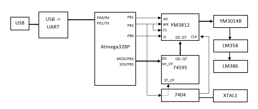
- During initialization, set PB2 = 1 to block the input of
YM3812
- We pass the register address
2.1 PB1 = 0 (A0 = 0)
2.2 We transmit the register address bytes via the SPI interface. Data is stored in shift register74595
2.3 PB2 = 0 (WR = 0, CS = 0). Chip 7404 inverts the signal and supplies 1 to the input of ST_CP74595
, which switches its outputs Q0..Q7.YM3812
writes register address
2.4 PB2 = 1 (WR = 1, CS = 1) - We pass the value of the register
3.1 PB1 = 1 (A0 = 1)
3.2 We transmit data bytes via the SPI interface similarly to p.2.2
3.3 PB2 = 0 (WR = 0, CS = 0).YM3812
writes data
3.4 PB2 = 1 (WR = 1, CS = 1)
An inverter 7404
and quartz XTAL1
implements a rectangular pulse generator with a frequency of 3.579545 MHz, which is necessary for operation of the YM3812
.
YM3014B
converts a digital signal into an analog signal, which is amplified by the LM358
operational amplifier.
The LM386
audio amplifier LM386
needed so that passive speakers or headphones can be connected to the device, as LM358
power is not enough.
Now let's try to extract the sound from all this. The first thing I (and probably not only me) thought about was how to make it all work in DosBox. Unfortunately, playing out of the box with the Adlib hardware will not work. DosBox does not know anything about our device, and does not know how to transmit OPL2 commands anywhere (so far it does not).
The author of the project offers a sketch for Teensy, working as a MIDI device. Naturally, the sound will consist of pre-compiled instruments and the sound will be different, we will get an emulation of a MIDI device on an OPL2 chip. I don’t have Teensy, and I couldn’t try this option.
Serial Port Operation
There is a sketch SerialPassthrough . With it, we can transmit commands through the serial port. It remains only to implement support in DoxBox. I used the version from SVN: svn://svn.code.sf.net/p/dosbox/code-0/dosbox/trunk
In the src/hardware/adlib.cpp
we change the implementation of OPL2:
#include "serialport/libserial.h" namespace OPL2 { #include "opl.cpp" struct Handler : public Adlib::Handler { virtual void WriteReg( Bit32u reg, Bit8u val ) { //adlib_write(reg,val); if (comport) { SERIAL_sendchar(comport, reg); SERIAL_sendchar(comport, val); } } virtual Bit32u WriteAddr( Bit32u port, Bit8u val ) { return val; } virtual void Generate( MixerChannel* chan, Bitu samples ) { Bit16s buf[1024]; while( samples > 0 ) { Bitu todo = samples > 1024 ? 1024 : samples; samples -= todo; adlib_getsample(buf, todo); chan->AddSamples_m16( todo, buf ); } } virtual void Init( Bitu rate ) { adlib_init(rate); LOG_MSG("Init OPL2"); if (!SERIAL_open("COM4", &comport)) { char errorbuffer[256]; SERIAL_getErrorString(errorbuffer, sizeof(errorbuffer)); LOG_MSG("Serial Port could not be opened."); LOG_MSG("%s", errorbuffer); return; } if (!SERIAL_setCommParameters(comport, 115200, 'n', SERIAL_1STOP, 8)) { LOG_MSG("Error serial set parameters"); SERIAL_close(comport); return; } } ~Handler() { if (comport) SERIAL_close(comport); } private: COMPORT comport; }; }
Before assembly, replace the COM port number with the current one.
If you remove the comment in the line //adlib_write(reg,val);
, then the sound will play simultaneously through the emulator and device.
In the DosBox setup, you will need to specify the use of OPL2:
[sblaster] oplemu=compat oplmode=opl2
Here's how I got it:
It looks pretty bulky. Even if you use Arduino instead of the breadboard, you need to connect the wires. The port number on the system may change and you will have to rebuild the DosBox. I really wanted to bring everything to some concise look, remove unnecessary parts and assemble everything on one board.
OPL2-USB
There was an idea, and why not make an independent device with a minimum of components and troubles when connected. First, you can remove the 74595
and use the atmega ports. Here it is used only to reduce the number of wires. Secondly, you can use a ready-made crystal oscillator and get rid of the 7404
chip. An audio amplifier is also not needed if you connect the device to the speakers. And finally, you can get rid of USB-UART if you connect the atmega to USB directly, for example using the V-USB library: https://www.obdev.at/products/vusb/index.html . In order not to bother with writing drivers and installing them, you can make the microcontroller a custom HID device.
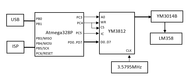
Ports B and C are partially busy connecting to the ISP programmer and quartz. Port D remained completely free, we use it for data transfer. I assigned the remaining ports in the PCB design process.
The full scheme can be studied here: https://easyeda.com/marchukov.ivan/opl2usb
LED1
with its resistor is optional and during assembly I did not install them. The U4 fuse is needed so as not to accidentally burn the USB port. It can also not be set, but replaced with a jumper.
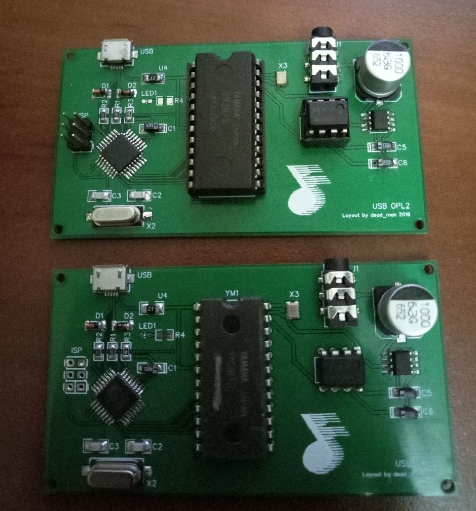
To make the device compact, I decided to try to assemble it on SMD components.
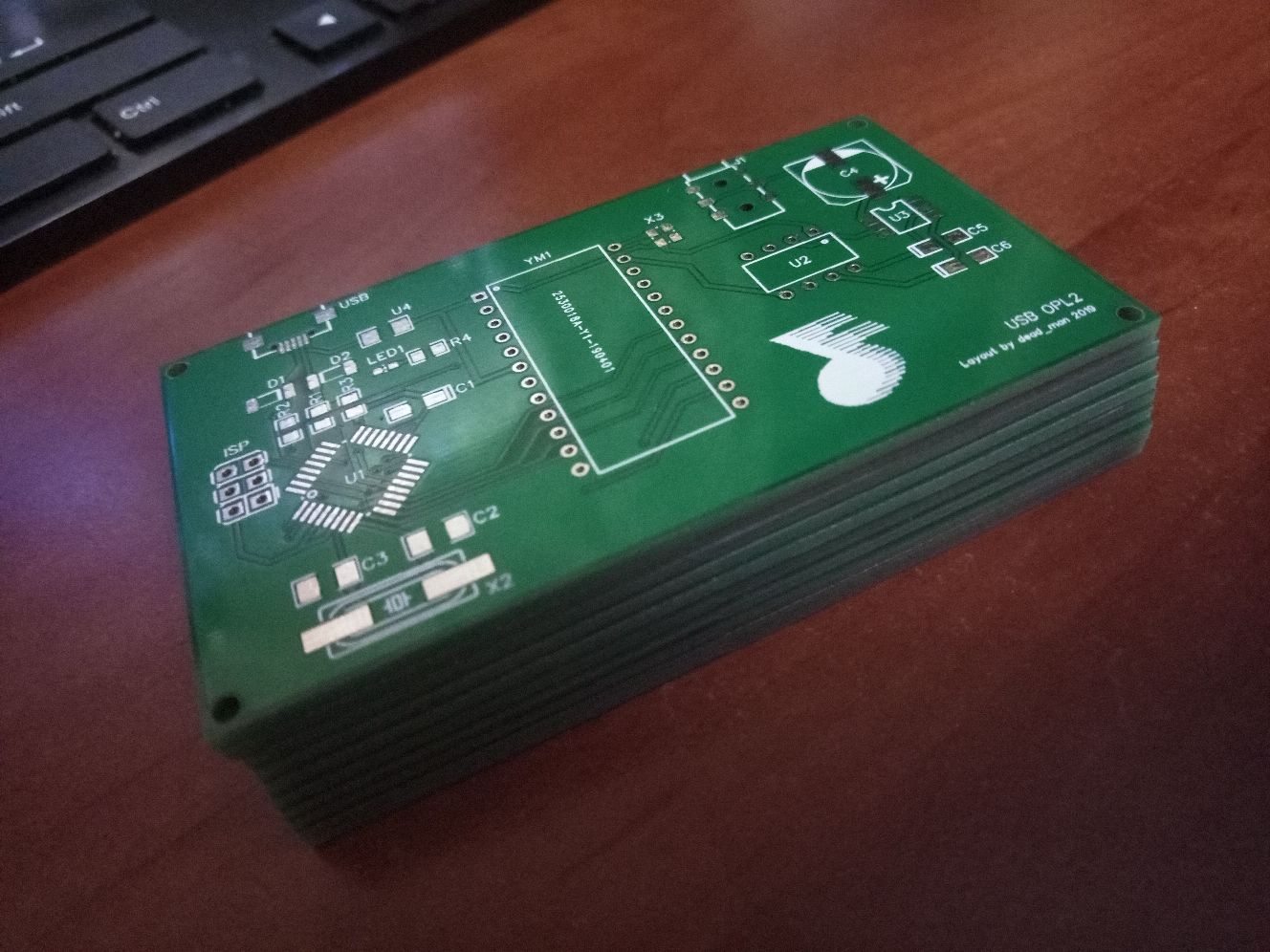
"Safe" option in heat shrink 50 / 25mm
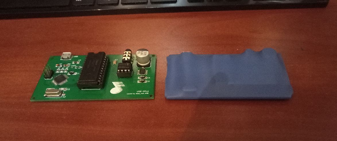
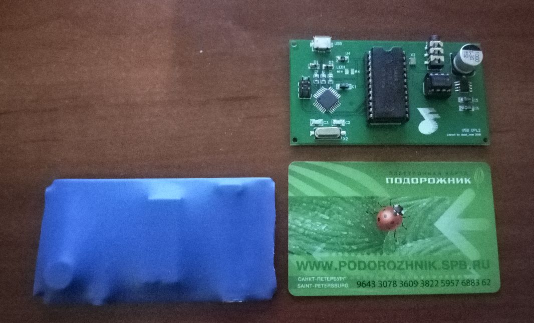
Digital part on the left, analog on the right.
For me, this was the first experience in designing and assembling a finished device and could not do without jambs. For example, the holes in the corners of the board should be 3 mm in diameter for racks, but they turned out to be 1.5 mm.
The firmware can be viewed on github . In the earlier version, one command was sent with one USB packet. Then it turned out that on dynamic tracks DosBox starts to slow down due to the large overhead and low speed of USB 1.0, DosBox hangs on sending a packet and receiving a response. I had to make an asynchronous queue and send commands in batches. This added a slight delay, but it is not noticeable.
V-USB setup
If we already figured out sending data to the YM3812 earlier, then USB will have to tinker with.
Rename usbconfig-prototype.h
to usbconfig.h
and add it (below are only the edits):
// . define #define F_CPU 12000000UL // #define USB_CFG_IOPORTNAME B #define USB_CFG_DMINUS_BIT 0 #define USB_CFG_DPLUS_BIT 1 #define USB_CFG_HAVE_INTRIN_ENDPOINT 1 // 20 #define USB_CFG_MAX_BUS_POWER 20 // , usbFunctionWrite #define USB_CFG_IMPLEMENT_FN_WRITE 1 // ( OPL2) #define USB_RESET_HOOK(resetStarts) if(!resetStarts){hadUsbReset();} // . #define USB_CFG_DEVICE_ID 0xdf, 0x05 /* VOTI's lab use PID */ #define USB_CFG_VENDOR_NAME 'd', 'e', 'a', 'd', '_', 'm', 'a', 'n' #define USB_CFG_VENDOR_NAME_LEN 8 #define USB_CFG_DEVICE_NAME 'O', 'P', 'L', '2' #define USB_CFG_DEVICE_NAME_LEN 4 // , HID- #define USB_CFG_DEVICE_CLASS 0 #define USB_CFG_INTERFACE_CLASS 3 // usbHidReportDescriptor #define USB_CFG_HID_REPORT_DESCRIPTOR_LENGTH 22 // INT0, PCINT0 #define USB_INTR_CFG PCICR #define USB_INTR_CFG_SET (1 << PCIE0) #define USB_INTR_CFG_CLR 0 #define USB_INTR_ENABLE PCMSK0 #define USB_INTR_ENABLE_BIT PCINT0 #define USB_INTR_VECTOR PCINT0_vect
In the main.c
file, we define the parcel data structures
// #define BUFF_SIZE 16 // - struct command_t { uchar address; uchar data; }; // struct dataexchange_t { uchar size; struct command_t commands[BUFF_SIZE]; } pdata;
Declare a handle for HID
PROGMEM const char usbHidReportDescriptor[] = { // USB report descriptor 0x06, 0x00, 0xff, // USAGE_PAGE (Vendor Defined Page) 0x09, 0x01, // USAGE (Vendor Usage 1) 0xa1, 0x01, // COLLECTION (Application) 0x15, 0x00, // LOGICAL_MINIMUM (0) 0x26, 0xff, 0x00, // LOGICAL_MAXIMUM (255) 0x75, 0x08, // REPORT_SIZE (8) 0x95, sizeof(struct dataexchange_t), // REPORT_COUNT 0x09, 0x00, // USAGE (Undefined) 0xb2, 0x02, 0x01, // FEATURE (Data,Var,Abs,Buf) 0xc0 // END_COLLECTION };
Event handlers:
// . static uchar currentAddress; static uchar bytesRemaining; // uchar usbFunctionWrite(uchar *data, uchar len) { if (bytesRemaining == 0) return 1; if (len > bytesRemaining) len = bytesRemaining; uchar *buffer = (uchar*)&pdata; memcpy(buffer + currentAddress, data, len); currentAddress += len; bytesRemaining -= len; if (bytesRemaining == 0) { for (int i = 0; i < pdata.size; ++i) { struct command_t cmd = pdata.commands[i]; if (cmd.address == 0xff && cmd.data == 0xff) // OPL2 FFFF opl_reset(); else opl_write(cmd.address, cmd.data); } } return bytesRemaining == 0; } // USBRQ_HID_SET_REPORT usbMsgLen_t usbFunctionSetup(uchar data[8]) { usbRequest_t *rq = (void*)data; if ((rq->bmRequestType & USBRQ_TYPE_MASK) == USBRQ_TYPE_CLASS) { if (rq->bRequest == USBRQ_HID_SET_REPORT) { bytesRemaining = sizeof(struct dataexchange_t); currentAddress = 0; return USB_NO_MSG; } } return 0; /* default for not implemented requests: return no data back to host */ } // extern void hadUsbReset(void) { opl_reset(); }
I recommend these Russian-language articles about V-USB:
http://microsin.net/programming/avr-working-with-usb/avr-v-usb-tutorial.html
http://we.easyelectronics.ru/electro-and-pc/usb-dlya-avr-chast-2-hid-class-na-v-usb.html
DosBox Support
The code for DosBox can be viewed in the same repository .
To work with the device on the PC side, I used the hidlibrary.h
library (unfortunately, I did not find links to the original), which had to be modified a bit.
I decided not to touch the OPL emulator, but to implement my own separate class. Switching to USB in configs now looks like this:
[sblaster] oplemu=usb
In the constructor of the Adlib module in adlib.cpp
add the condition:
else if (oplemu == "usb") { handler = new OPL2USB::Handler(); } else {
And in dosbox.cpp
new configuration option:
const char* oplemus[]={ "default", "compat", "fast", "mame", "usb", 0};
Compiled exe can be picked up here: https://github.com/deadman2000/usb_opl2/releases/tag/0.1
Video
Connection:
Sound recorded through a sound card:
Results and plans
I was satisfied with the result. It’s easy to connect the device, no problems. Of course, my modifications of DosBox will never get into the official version and popular branches, as This is a very specific solution.
Next in line is picking the OPL3. There is still an idea to build a tracker on OPL chips