For example, in some test laboratory there is a need to automate the power reset of the studied / tested devices at strictly set time points with reference to the absolute scale (for example, on Monday at 10:00 in the morning). However, the task is complicated by the fact that the decision on the possibility of performing a power management operation is affected by the current state of other hardware resources of the device under study (for example, one or another level on the output GPIO line).
The latter circumstance complicates the solution somewhat and makes us think about using some external hardware module in which there is support for the necessary hardware resources to solve such a problem, namely: relays, real-time clocks, input GPIO lines.
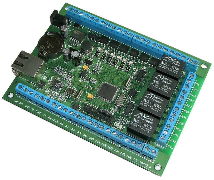
The first experiments we made using the Arduino platform. However, when it became necessary to copy this solution in large quantities with stable quality, they began to look towards ready-made solutions. As a result, we adjusted the system using an external Laurent-5 hardware module with the ability to monitor the Ethernet control process.
For specifics, we needed to briefly reset the power of the tested device every day strictly at 07:00 in the morning. However, a reset should never be carried out if the device continues to perform critical operations. In this case, a high logic level (+3.3 V) is set on the output discrete GPIO line of the device.
The Laurent-5 module was connected to the test device as follows. The device ready signal was brought to the input discrete line IO_1. And the power of the device was forwarded through normally closed relay contacts RELE_1. If the relay is turned on, the power to the device under test is cut off.

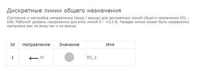
To configure the system, first of all, you need to change the direction for the GPIO IO_1 of the Laurent-5 “input” module. The easiest way to configure is through the Web interface (the default address is 192.168.0.101). We go to the section "General Lines IO1 - IO8" on the main control panel.
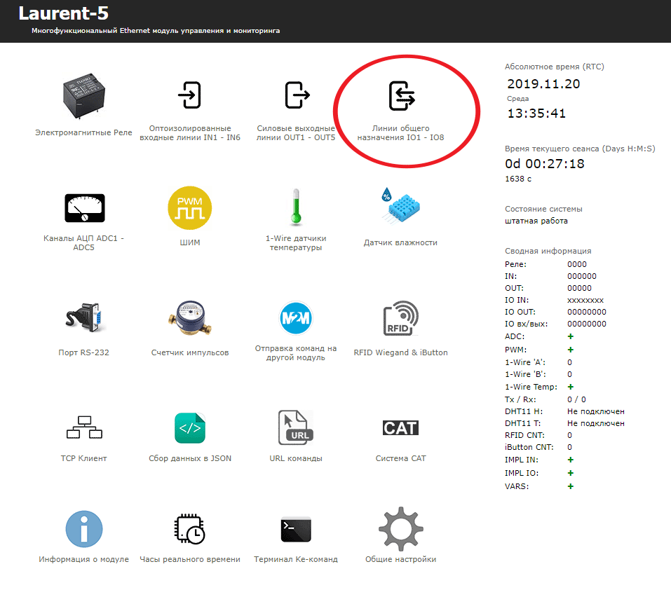
We click on the “arrow” at line IO_1 and change the direction of this GPIO line to the “on” state to analyze the state of the “readiness” line of the device under test.
Next, we will create logical CAT rules that will serve the automation of the “readiness” line analysis and control the relay.
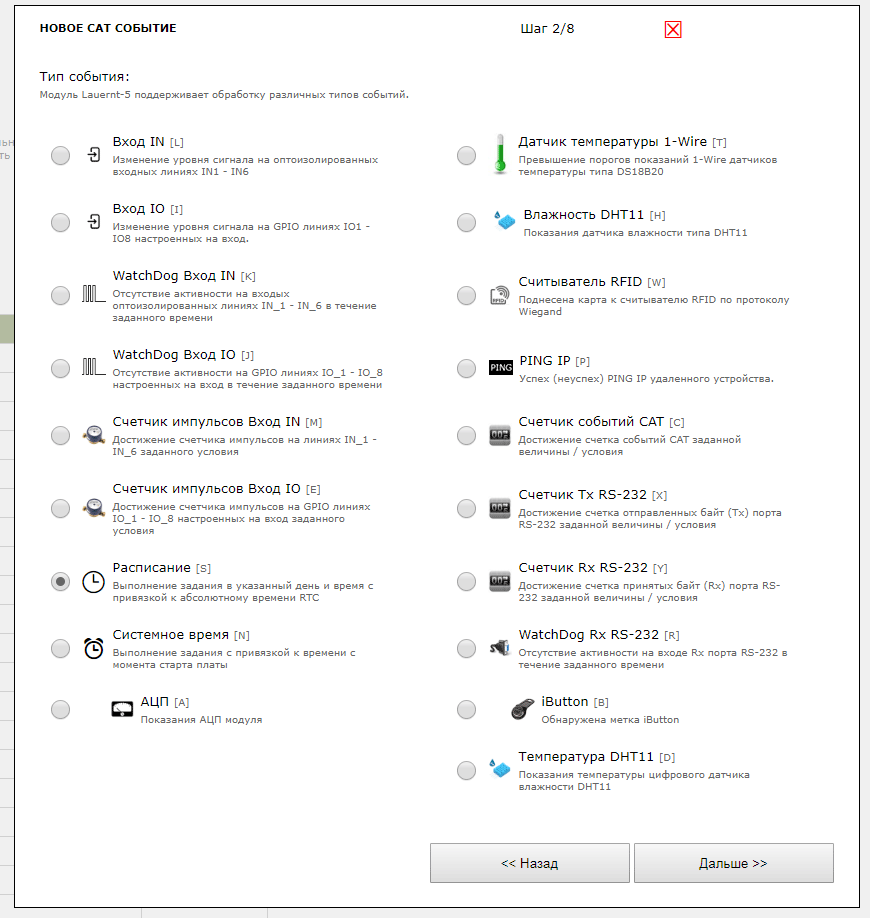
We go into the CAT section and click on the "Create a new event" button. A window will appear in which ID = 1 will be assigned to the new logical rule.
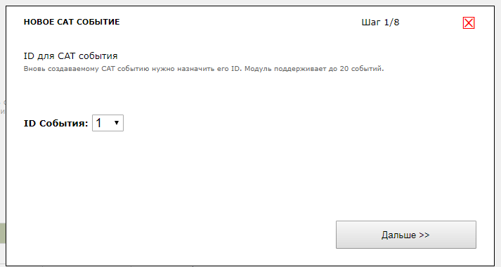
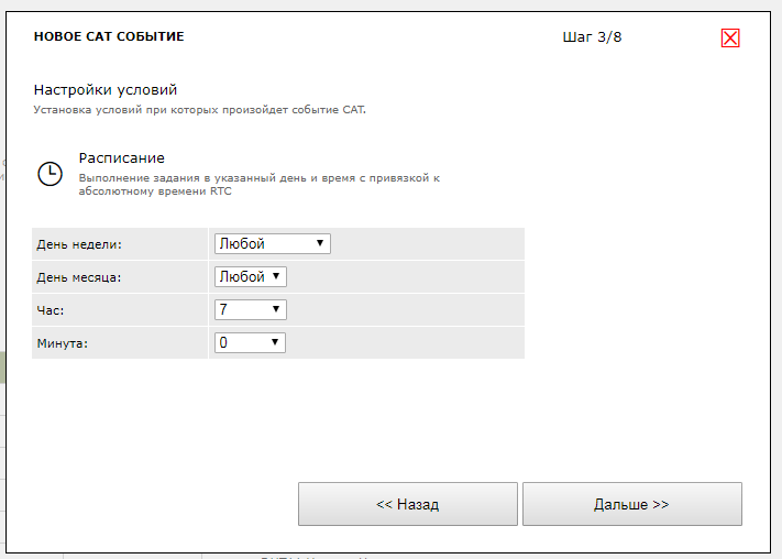
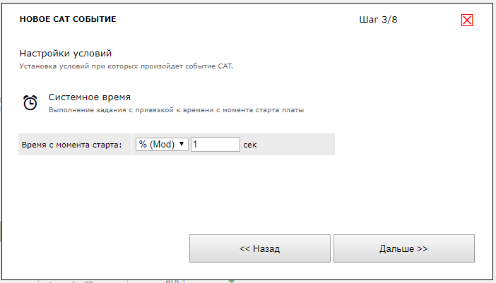
Choose the type of RTC event - the task will be completed at the specified time.
In the event settings, we indicate the response time - every day at 07:00 in the morning.
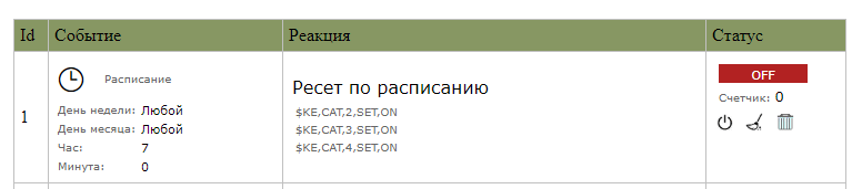
In response to the occurrence of this event using Ke-commands, we enable the operation of CAT events 2,3 and 4, which we will create further. Additional logical rules are needed in order to analyze the signal “readiness” of the device and to avoid power reset if it is not ready for this.

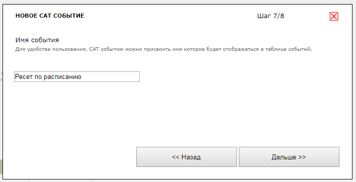
Let's give a symbolic name to this logical rule for clarity.
As a result, a new event with ID = 1 will appear in the list of logical rules:
Add the following logical rule with ID = 2, which will execute on a timer with a frequency of 1 time per second.

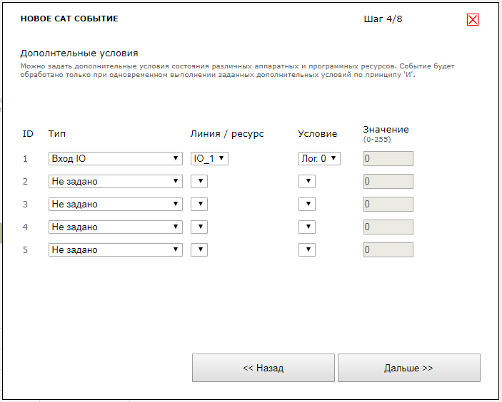
We indicate an additional condition that must be satisfied in order for the logical rule to work, namely, we specify the need for a low logical level at IO_1, thereby signaling that the device is ready for a power reset.
If all conditions are met, then turn off events 2,3 and 4. We will reset the response counter for event 3 (see below) and turn on the relay RELE_1 for 4 seconds after which it will automatically return to its original (off) state.

However, what should I do if the device “freezes” and the alarm sounds all the time? For this, we will use events with ID = 3 and 4 in which we implement a semblance of a watchdog timer with the sending of an alarm message if, within a specified time, the device has not signaled its readiness for a hardware reset.
Let's create an event with ID = 3 according to the usual timer with a response frequency of once every 1 second. This event will not actually do anything, just send an empty $ KE command. However, with each operation, the counter of operations of this event will increase. Using a logical rule with ID = 4, we will monitor this value and if it exceeds a certain threshold (for example, 300 operations, which corresponds to 5 minutes), we will stop the operation and increment the value of the program variable VAR_1 for subsequent analysis of the number of failed operations.
In total, a set of logical rules will look as follows. To start the entire system, it is enough to enable event processing with ID = 1.
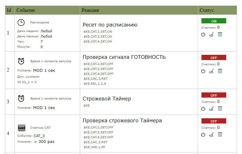
And then there will be the following: every day at 07:00 a logical rule with ID = 1 will be triggered. In this case, event processing with IDs 2, 3 and 4 will be included as a reaction. If the device under test is ready to reset power (logical level 0 to signal line) - within the framework of the rule ID = 2, the processing of events 2-4 will be turned off, the operation counter for the 3rd rule is reset for some reason, and the device is reset by powering the relay for a short time.
In the parallel, we start the guard timer counting down with a clock once per second. By checking the value of the watchdog timer within the framework of the ID = 4 rule, we can crash the wait and signal the failure of the entire operation on that day by incrementing the program variable VAR_1, the value of which can then be requested via TCP / HTTP for subsequent analysis.