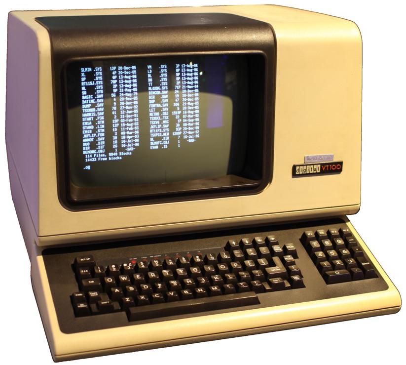
The DEC VT100 terminal, sold in excess of a million units, had a 80 × 24 character display
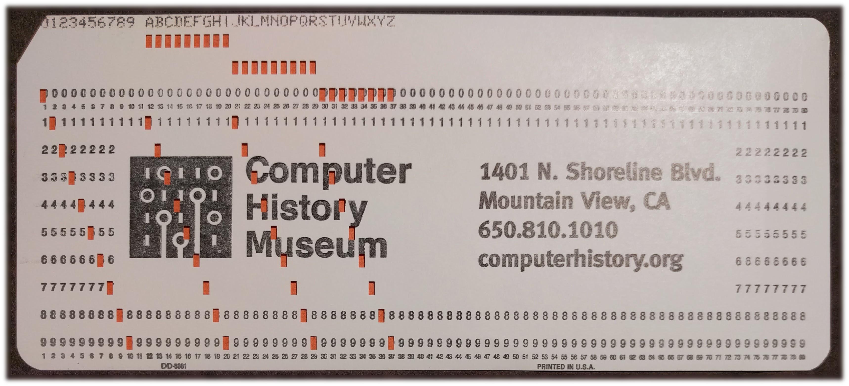
How to explain the popularity of terminals 80 × 24 and 80 × 25 characters? A recent post on another blog inspired me to do a little research. Punched cards are obviously the source of 80-character strings, and they write about this quite often. However, what about 24 or 25 lines on the screen? There are many theories, but I found a simple answer: IBM, and in particular, its dominance in the terminal market. In 1971, IBM introduced a terminal with a display of 80 × 24 characters (model 3270), and soon it became the best-selling terminal, forcing the rest to equal the size of 80 × 24. The display for the IBM PC added another line, and made the size 80 × 25 standard in the PC world. The influence of these systems remains valid even decades later: lines of 80 characters are the standards to this day, as well as terminal windows 80 × 24 and 80 × 25.
In this article, I will discuss this story in detail, including some other systems that played a key role in it. The market for CRT terminals began, in fact, with the release of the IBM 2260 Display Station in 1965, created on the basis of such entertaining technologies as sound delay lines . This led to the emergence of the popular IBM 3270 display, and further, to the common and inexpensive terminals such as the DEC VT100. In 1981, IBM released the DataMaster microcomputer. Now it is almost forgotten, but it has greatly influenced the IBM PC, including its display. The article also explores the terminal market of the 1970s and 1980s; from them it becomes clear that the popularity of display sizes was determined by market rather than technological forces.
Some theories regarding 80 × 24 and 80 × 25 sizes
Arguments about the origin of terminal sizes have been put forward for several decades, but a detailed and interesting theory was presented in the article already mentioned. In short, it says that the 80 × 25 display was used because it was compatible with 80-column punch cards from IBM, it fit well on a TV screen with an aspect ratio of 4: 3, and fit in a 2K RAM. This led to the emergence of 80 × 25 terminals such as the DEC VT100 in 1978. Its immense popularity made it the standard, and spawned an abundance of 80 × 25 terminals. Such, at least, is the theory.
80-column displays really came from punch cards, and the VT100 really became the standard, but then this theory falls apart. The biggest problem is that the VT100 displays were 80 × 24, not 80 × 25. In addition, the instructions describe that the VT100 had 3K memory, of which 2.3 K used the screen, and the 8080 microprocessor used the rest. Each line was stored in memory with three additional bytes at the end, used as pointers for scrolling. Therefore, the video memory of the terminal did not fit in 2K. Finally, until the 1980s, most displays were 80 × 24, not 80 × 25.
Other theories were suggested on the Software Engineering StackExchange and Retrocomputing StackExchange sites, claiming that 80 × 24 terminals appeared for technical reasons such as TV refresh rates, memory sizes, typography, typewriter history, and so on. However, theories that 80 × 24 display is an inevitable consequence of technology have a fundamental problem: in the mid-1970s, the terminals had dozens of different size options, for example, 31 × 11, 42 × 24, 50 × 20, 52 × 48 , 81 × 38, 100 × 50 and 133 × 64. It is clear that no technological limitations forced the terminals to accept a certain size. On the contrary, with the improvement of technology, all of these terminals disappeared, and by the beginning of the 1980s, mainly 80 × 24 terminals remained. This says that standardization, not technology, has become a key factor.
I will briefly summarize why technical factors did not greatly affect the size of the terminal. Televisions in the USA used 525 scan lines and a refresh rate of 60 Hz, and 40% of the terminals used other values (in the 1980s, home computers had to work with NTSC TVs with their own limitations, so they often used strings of 40 or 64 characters) . The frequency and bandwidth did not make displays of a certain size, because the terminals displayed characters with different sizes of matrices.
The raster terminal draws each character from a matrix of points. In 1975, 5x7 and 7x9 matrices were most often used. Often the matrix had fields - Apple II used a 5x7 matrix with fields, which ultimately amounted to a field of 7x8 pixels. Some systems (for example, IBM CGA) used an 8x8 borderless matrix to support graphic characters whose images were in contact with each other. Other systems used larger matrices. IBM Datamaster used a matrix of 7 × 9 dots per field of 10 × 14 dots, while the Quotron 800 had a 16 × 20 matrix. As a result, a terminal with a size of 80 × 24 characters may require a completely different number of pixels in general, depending on the size of the matrix. This is the disadvantage of the statement that the size of the terminals was determined by the number of scan lines and throughput.
Although the cost of memory was significant, DRAM chip volumes grew four times every three years, making memory only a temporary limitation. The aspect ratio of the screen was not a determining factor, since often the proportions of the characters did not coincide with the proportions of the screen. Even on CRTs with 4: 3 aspect ratios, terminals could use text of other proportions, leaving part of the screen blank. The special sizes of the terminals were not uncommon - for example, the Datapoint 2200 screen was unusually elongated to repeat the size of the punch card. The Teletype Model 40 had an unusual aspect ratio of 2: 1. The technology, of course, influenced the process, but it did not stop the early manufacturers from creating different terminals, from 32 × 8 to 133 × 64.

Teletype Model 40
The growing popularity of CRT terminals
Now a small part of the history of CRT terminals can help us. Many readers are familiar with ASCII terminals — such as individual DEC VT100 terminals, serial terminals connecting to a PC, or serial ports on Arduino-type boards. Terminals of this type come from teleprinters - electromechanical keyboards / printers that appeared at the beginning of the 20th century. Teletype, which was popular with newspaper and computer scientists in the 1970s (the Linux / dev / tty device is named after him), is known most of all. Teletypes usually displayed lines of 72 characters on a paper roll.
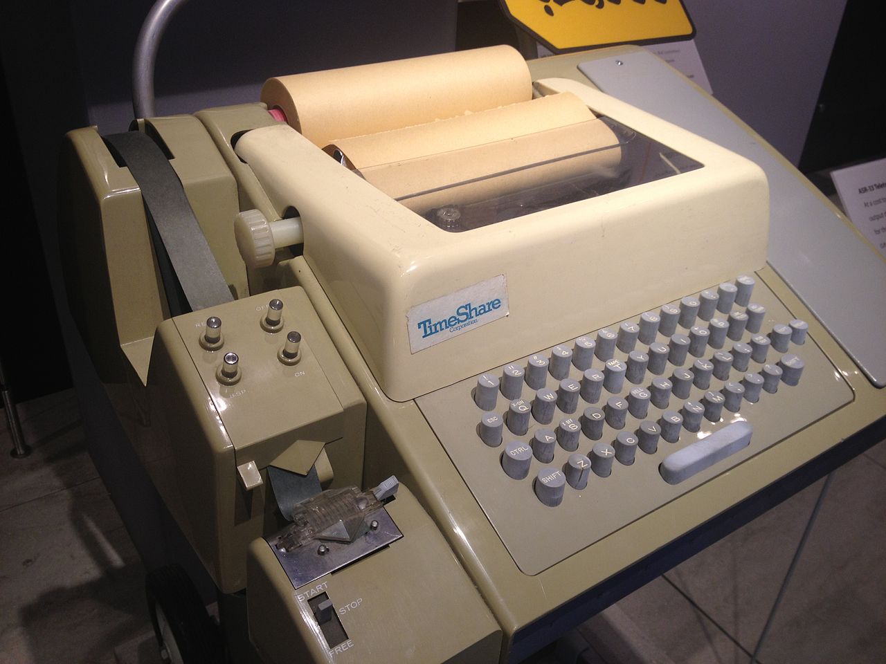
Teletype ASR33 transmitted ASCII characters and printed 72 characters per line. From 1963 to 1981, hundreds of thousands of copies of this model were produced. On the left is a punch tape reader and puncher.
In the 1970s, the market for replacing CRT terminals was large and profitable. AT&T introduced the Teletype Model 40 in 1973, and this CRT terminal displayed 80 x 24 characters. Many other companies introduced competing CRT terminals, and Teletype-compatible devices have become an entire market segment. By 1981, these terminals were used in different roles, and not just as a replacement for teleprinters, and their name changed to “ASCII terminals”. By 1985, CRT terminals had achieved unprecedented success, and about 10 million units were operating in the United States.

A terminal from the IBM 3270 line, specifically, the 3278 model.
However, there is a parallel world of mainframe terminals that may not be familiar to many readers. In 1965, IBM introduced the IBM 2260 Display Terminal, and thereby "approved" the CRT terminals, which were previously considered a "fashionable novelty." This terminal dominated the market until IBM replaced it with the cheaper and more advanced IBM 3270 in 1971. Unlike asynchronous ASCII terminals that transmit single keystrokes, these terminals were set up for block operation, essentially exchanging large blocks of characters with the mainframe. The 3270 terminal was pretty smart: the user could fill in the marked fields on the screen, and then transfer all the data at once by pressing the Enter key (which is why modern keyboards have an Enter key). Sending a data block was a more efficient method than sending individual clicks, and allowed mainframes to support hundreds of terminals at once.
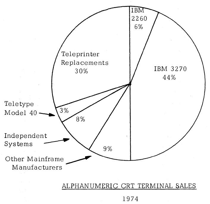
The chart below shows the state of the terminal market for 1974. It was controlled by the IBM 3270, which had supplanted the 2260th by that moment. With 50% of the market, IBM essentially defined the characteristics of a CRT terminal. Replacing teleprinters was a large and influential market; The Teletype Model 40 was a modest model, but with growing importance. Although DEC will soon become a major player, he was in the Independent Systems sector that year.
IBM 2260 video display terminal
The IBM 2260 was introduced in 1965, and it was one of the first video display terminals. Video displays with vector graphics appeared many years before, back in the early 1950s. These were vector terminals that received a picture using arbitrary lines, not pixels. And although they could display letters using lines, they were extremely expensive and were used for plotting.
The IBM 2260 performed three roles: remote data entry instead of punch cards, queries (viewing records in the database), and the system console. This compact terminal weighed 20 kg, and its size allowed it to fit in place of a standard typewriter. See how thick his keyboard is: he used the complex mechanism of an old IBM punch, with levers, discs and electromagnets.

IBM 2260 Display Station
You may be surprised that IBM was able to create such a compact terminal using 1965 technology. The trick is that it was just a CRT display with a keyboard; all control logic, character generation, storage and interfaces were contained in a 450 kg cabinet (photo below). The terminal with the keyboard was called the IBM 2260 Display Station, the cabinet with logic was called the IBM 2848 Display Control, and people called the whole system simply the 2260th. The cabinet contained circuits for controlling several terminals simultaneously, up to 24 pieces. He generated pixels for them and sent video signals to monitors, which could be located at a distance of up to 600 m from it.
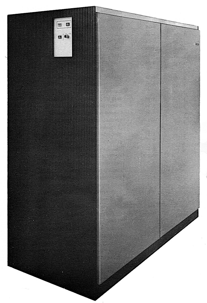
The IBM 2848 Display Control supported up to 24 terminals. The cabinet was one and a half meters wide and weighed 450 kg.
One of the most interesting features of the 2260th is the audio delay lines used to store pixels. The bits were stored in the form of sound pulses sent to a nickel wire about 15 m long. The pulses went through the wire and exited from its other end exactly after 5.5545 ms. Sending a pulse (or not sending it to indicate 0) every 500 ns, the wire could store 11,008 bits in itself. A pair of wires created a buffer that stored pixels for 480 characters.
The delay line produced 1 bit every 500 ns. Two delay lines were connected to the buffer, providing bit output twice as fast: every 250 ns. The data was divided into 256 “slots”, one per vertical scan line (the slots were a clean concept, because the delay line just fed a bit stream). 240 slots contained data, and 16 were empty for horizontal beam return . Each slot contained 86 bits: 7 bits for 12 rows of characters, and two parity bits (each scan line was divided into two displays, so the slot represented 6 characters on an even display and 6 on an odd one). Six slots made up a vertical column of characters: one slot stored a binary decimal value, and five - pixels. Thus, in each buffer, data was stored for 480 characters to support 40x6 displays. Two buffers supported a pair of 40 × 12 displays, and four supported a pair of 80 × 12 displays.
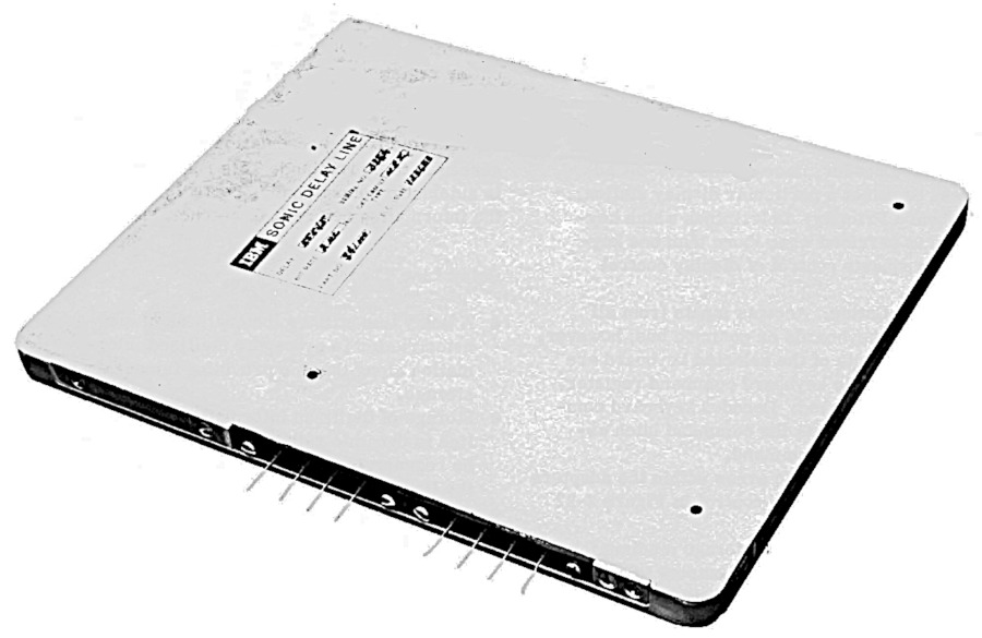
The sound delay module for the IBM 2260 display. It contained about 15 m of nickel wire in coils.
The sound delay lines had several problems. Firstly, it was necessary to constantly update the data: when the bits came out from one end of the wire, it was necessary to send them back to the other end. Secondly, the delay line did not have random access: to update a character, it was necessary to wait a few milliseconds until all the bits went their way. Thirdly, the delay line was sensitive to vibration; Wikipedia says that even heavy steps could disrupt the screen. Fourth, the speed of the delay line depended on temperature changes; before use, she needed to warm up for up to two hours in a row in a temperature-controlled cabinet. Given all these shortcomings, you may wonder why these delay lines were still used. The main reason is that they were much cheaper than memory on stitched cores. The consistent nature of the delay line also worked well with the consistent nature of the raster display.
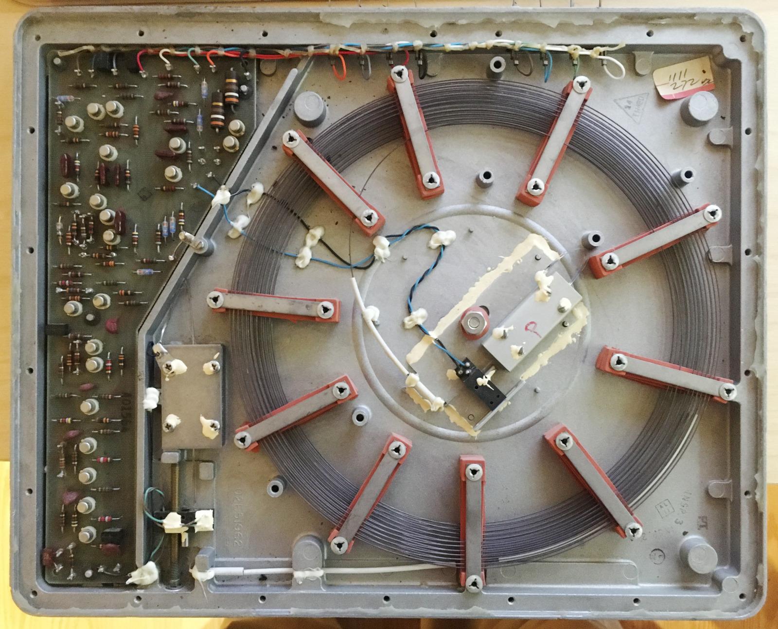
The nickel wire in the coil had converters at both ends (in the center and bottom left, where the twisted wires are connected to them). To adjust the delay, the rod with the wire (bottom left) shifted the position of the converter on the wire. The metal boxes at the ends of the wires are shock absorbers that prevent reflection.
The photo below shows the 2260 Model 2 screen, with 12 lines of 40 characters each (Model 1 had 6 lines of 40 characters each, and Model 3 had 12 lines of 80 characters each). Note the double line spacing; in fact, the control module generated 24 lines of text, but lines through one were sent to two different terminals. A very strange approach, but it shared the high cost of control iron between the two terminals. Another strange characteristic of the 2260th was vertical scan lines, in contrast to the horizontal scan lines of most video displays and televisions.
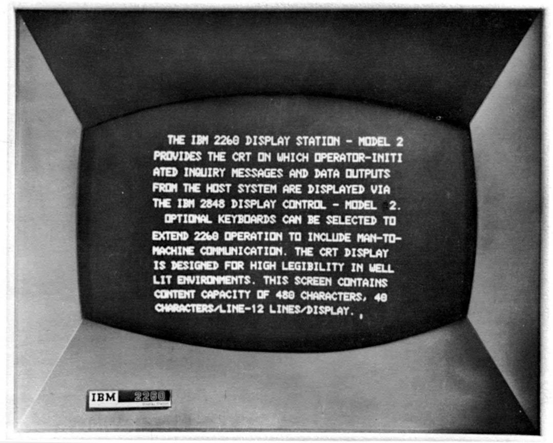
Display IBM 2260
Each character was identified by a 6-bit EBCDIC code , which yielded a set of 64 characters (without lowercase letters). Another strange feature of the 2260th is the conversion of 6-bit characters into a 5x7 pixel block. To do this, we used a special matrix on magnetic cores, in which there were cores only for single bits, but for zero bits it was not, so it worked like a read-only memory. As a result, you could see the symbols on the core matrix. The matrix stores nine 7-bit words for each of 64 characters: the first five words store a block of pixels, and the remaining four are a table for converting the EBCDIC character code to ASCII or vice versa, or codes for controlling the printer.
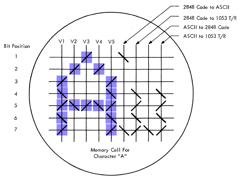
The delay lines stored the pixels that needed to be output, and they also stored EBCDIC codes for each character. The trick was to use an empty column of pixels between characters, providing a horizontal distance between characters. The system used it to store the binary-decimal value of a character, but turned off the display when this column was displayed so that this value was not displayed on the screen in the form of pixels. This made it possible to store the 6-bit value of the symbol almost free then.
The question that interests us is why did the 2260 have a display with 12 lines of 80 characters? A line length of 80 characters allowed the terminals to take the place of 80-column punch cards (for models with 40 characters in a line, the card was divided into 2 lines). As for the 12 lines, this, apparently, is the amount that the delay lines could provide without flickering.
250 ns per pixel and a refresh rate of 30 Hz give a maximum of 133,333 pixels that can be displayed. With 6x7 pixel characters and lines of 80 characters per line, 39.7 lines can be displayed. A vertical update eats away a third of the time due to interaction with the delay lines, which gives us 26.5 lines. Since 2260 separates the pixels between the two displays, this gives 13.25 lines per display, except for the horizontal update. Consequently, iron can support about 12 lines of text (although, perhaps, IBM first decided to support 12 lines, and then tweaked that iron).
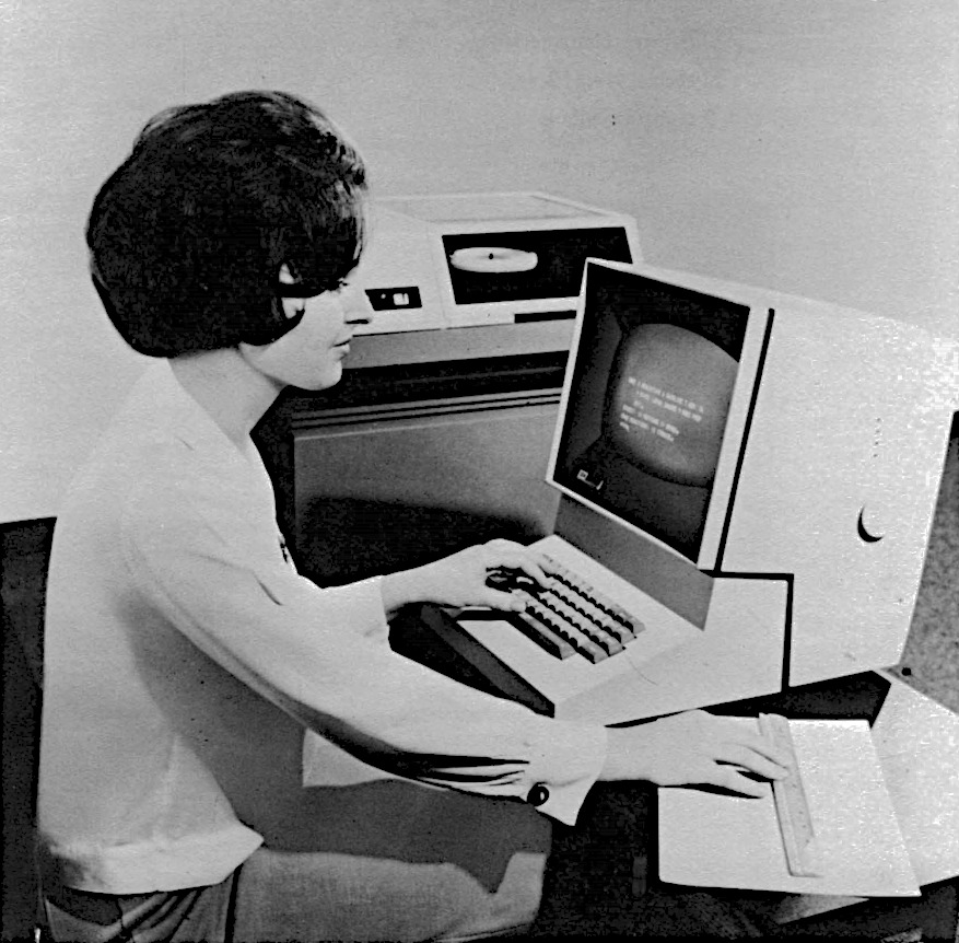
Photo from the operator's manual 2260
The IBM 2260 was a huge success, which led to an increase in the popularity of CRT terminals. The impact of the IBM 2260 is shown in the 1974 terminal report ; it lists about 50 terminals compatible with the IBM 2260. The IBM 2260 did not have an 80 × 24 display (although the machine generated an 80 × 24 matrix inside), but there were 40 × 12 and 80 × 12 displays, which made the 80 × 24 display next logical step.
IBM 3270 Video Display
In 1971, IBM released the IBM 3270 video display, which continued to dominate the CRT market. It supported a 40 × 12 display to allow for a smooth transition from the 2260th, but also supported a larger 80 × 24 display. The 3270th had more features than the 2260th — protected input fields, more efficient data transfer models, and text of adjustable intensity. He was also much cheaper than the 2260th, which ensured his popularity.
A 1974 Datapro report found that an IBM 2260 display cost from $ 1270 to $ 2140, and a controller from $ 15,715 to $ 86,365. In comparison, an IBM 3270 display cost from $ 4,000 to $ 7,435, and a controller from $ 6,500 to $ 15 725. A part of the electricians moved from the control module to the display itself, which affected their cost.
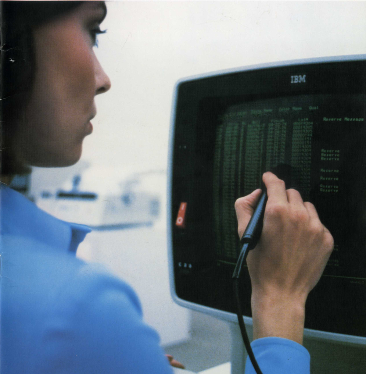
IBM 3270 terminal. A light pen was used to select data fields instead of a mouse. This is a later model in the terminal line, 3278; 43 lines of 80 characters are visible in the photo
The technologies used in the 3270th were from the next generation compared to the 2260th. Electron tubes and transistors were replaced by microelectronic circuits such as SLT , similar to integrated circuits. Instead of sound delay lines, 480-bit MOS shift registers were used. The 40 × 12 model used one bank of shift registers to store 480 characters. In the larger model, four banks of shift registers (1920 characters) were used to support the 80 × 24 display. In other words, in the 3270th storage, it worked in blocks of 480 characters for compatibility with the 2260th, and the use of four blocks gave an 80 × 24 display. 480 bits is a strange size that is not a power of two; but, unlike the matrix RAM chips, the shift registers did not have address bits, their structure was serpentine, so they could be of arbitrary size:
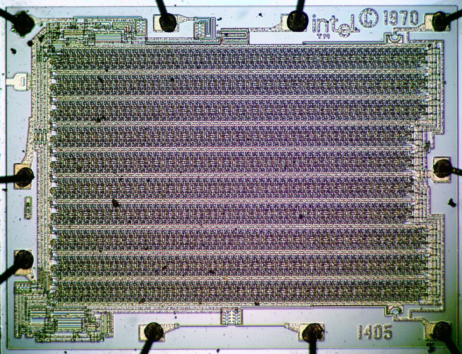
Shift register Intel 1405. It was not used in the IBM 3270, but worked in other terminals, for example, in the Datapoint 2200.
IBM provided comprehensive software support for the 3270 terminal. This had a major impact on the terminal market as it forced other manufacturers who wanted to race to produce compatible terminals. In particular, because of this, compatibility with the 3270th and 80 × 24 character display have become the de facto standard. In 1977, IBM introduced the 3278th, an improved version of the 3270 terminal, supporting 12, 24, 32, and 43 data lines. Also, there was added a status bar, "information area for the operator." New sizes of 32 and 43 lines did not take root, but the status line became a common feature among competitor terminals.
Industry reports show a change in the popular size of the terminal from the 1970s to the 1990s. Although in the 1970s (and maybe even earlier) there were already 80 × 25 displays, an 80 × 24 display was much more common. The widest variety of terminal sizes that existed in 1974 declined over time, and the market eventually settled at 80 × 24. By 1979, the most popular terminal was the DEC VT100 model, which had an 80 × 24 display and sold more than a million copies. The terminals began to support 132 × 24 size for compatibility with printers that print 132 characters per line, especially when larger 15 ”monitors started to get cheaper, but the most popular size was still 80 × 24. Even by 1991, the size was 80 × 25 met very rarely.
IBM PC and the popularity of the size of 80 × 25
Given the historical popularity of 80 × 24 terminals, why do so many modern systems use 80 × 25 windows? And this also happened thanks to IBM: the 80 × 25 display became popular with the advent of the IBM PC in 1981. A standard display card (MDA) produced 80 × 25 monochrome text, while a CGA card produced 40 × 25 and 80 × 25 in color. This size has become the default size for the Windows console, and a typical size for terminal windows on a PC.
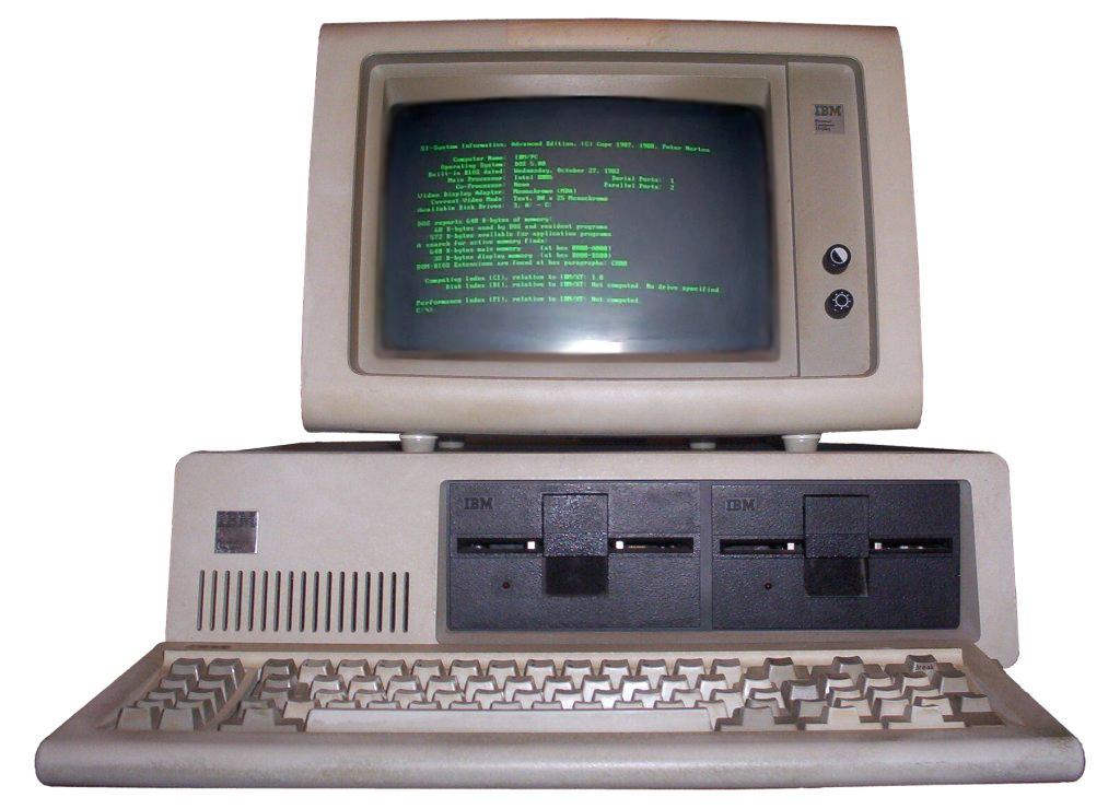
IBM PC with a 80 × 25 display that displays an MDA (Monochrome Display Adapter) card
Other popular computers at that time used 24 lines, for example, Osborne 1 and Apple II, so I was wondering why the IBM PC used 25. To find out, I contacted Dave Bradley and Mark Dean, two engineers who were at the origins of the IBM PC . They explained that the IBM PC was a descendant of the forgotten IBM DataMaster office computer, and many IBM PC design solutions stem from DataMaster. The IBM PC got the keyboard from DataMaster, only it was disconnected from the main module. Both systems used BASIC, however, the decision to order a BASIC interpreter for a PC from a tiny Microsoft company changed both of these companies more than anyone could have imagined. Both systems used Intel processors, an 8-bit 8085 in DataMaster, and a 16-bit 8088 in IBM PC. They had the same interrupt controller, DMA controller, parallel port, and timer chips. The 62-pin PC expansion bus was almost identical to that of the DataMaster.
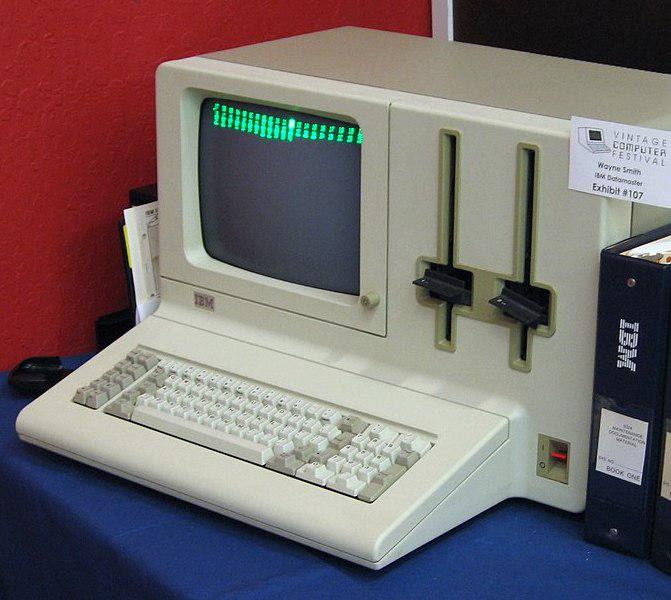
The IBM DataMaster System / 23 is a microcomputer announced in 1981, just a month before the IBM PC
The following is an outline of an early IBM PC project plan. He had to use an 80 × 24 display from DataMaster (which is codenamed LOMA), as well as 40 × 16 and 60 × 16 sizes, more suitable for TVs. Also mentioned in the diagram is a color graphics system with 280 × 192 pixels, the same resolution as Apple II had. But in the end, the IBM PC was not like this plan.

18 kHz is the horizontal scanning frequency used by the MDA card (18.432 kHz), and gives a higher resolution than 15.750 for NTSC)
The IBM PC developers managed to push a little more pixels into the display, and get a size of 320 × 200. When using an 8x8 character matrix, the updated graphics mode supported text of 40 × 25 characters, and the graphics mode with doubled resolution of 640 × 200 pixels supported text of 80 × 25. The monochrome graphic card (MDA) also gave a size of 80 × 25. In other words, the IBM PC eventually began to use an 80 × 25 text display because there were enough pixels on the display, and it also made it different from other systems, but these reasons were not the main motivation. In particular, PC developers were not limited by the need to ensure compatibility with other systems from IBM.
Conclusion
Many theories have proposed various technical reasons why a display size of 80 × 24 (or 80 × 25) is natural. I think that the wide variety of display sizes in the 1970s proves that you should not look for technological motivation for such a choice. The sizes of the displays simply converged to what IBM produced - first they were punch cards, then the IBM 2260 terminal, then the IBM 3270, and then the IBM PC. At first, the 72-column Teletype influenced the size of the terminals, but this size also disappeared in the pursuit of compatibility with IBM. As a result, the current situation arose with the division into sizes 80 × 24 and 80 × 25.