annotation
The MIPI interface is now becoming an increasingly popular interface for connecting cameras and displays. For this reason, more and more FPGA-based debugging kits contain on-board MIPI interface connectors - both for connecting cameras (s) and display (s). In order to start working with new technology or just to see what it is like, developers are trying to find a suitable guide on the Internet, which would describe the relevant nuances of the work. On the one hand, the test case should be easy enough to go up on the debugging kit, and on the other hand, it should give a fairly simple and broad understanding of what is happening in this test case.
The purpose of the article is to show how to start working with the MIPI interface using one of the latest debugging from Xilinx - SP701 , a camera with a MIPI interface from Digilent PCAM-5C and the Vivado + VITIS development environment (SDK) from Xilinx

Equipment list
Starting with the first release of VITIS and Vivado 2019.2, Xilinx gives developers the opportunity to generate a test case for working with the MIPI interface on the SP701 board. Previously, the project was available for the ZCU102 board, however, since the example required a rather specific camera, we did not have the opportunity to run a test project. With the release of the budget SP701 , which also connects the budget camera PCAM-5C, such an opportunity appeared.
PS0: the guide will not tell you what MIPI is, what it consists of, or any other theory that can be found on the Internet. Here we will focus on how to generate a test project. Further, using this project, you yourself can fasten the additional modules and video processing specified in the terms of reference for your project.
PS1: We will not rant, but focus on action. Only pictures, only hardcore.
Let's get started.
Required Software
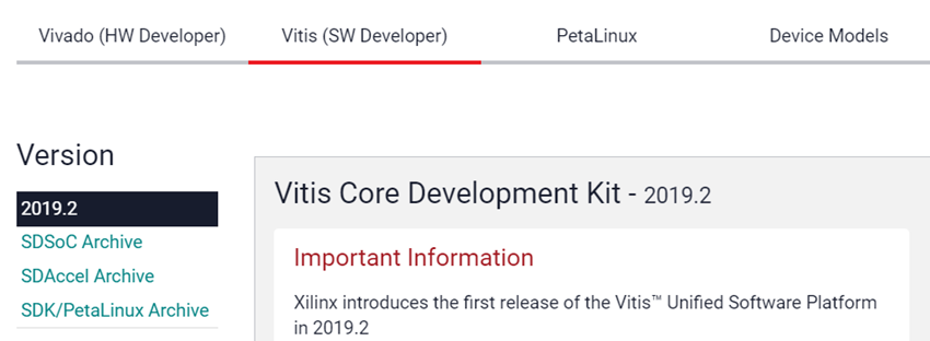
For this tutorial, we need Vivado 2019.2 and VITIS, which are downloaded from the link . VITIS contains Vivado, so there is no need to download both VITIS and Vivado, just download and install VITIS. Vivado will be installed automatically.
Step 1: Create a Vivado Project
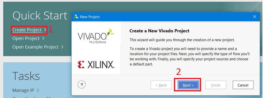
1. Launch Vivado 2019.2
2. Click “Create project” (1) :: Click “Next” (2)
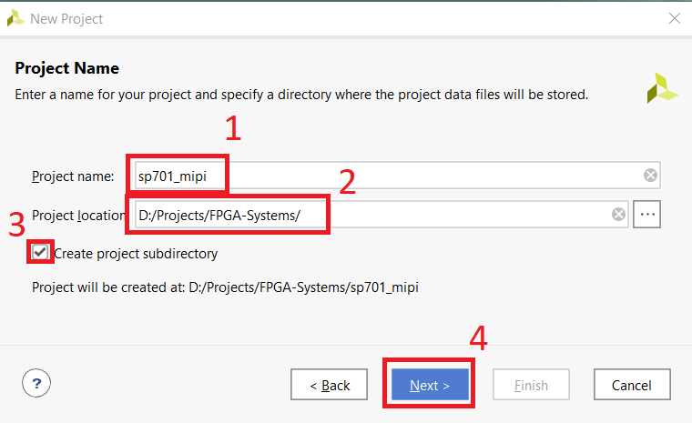
3. Specify “Project name” (1) :: Specify the project directory (2) :: Check the box (3) :: Click “Next” (4)
4. Select the type of project (1) :: Set the checkbox (2) :: Click “Next” (3)

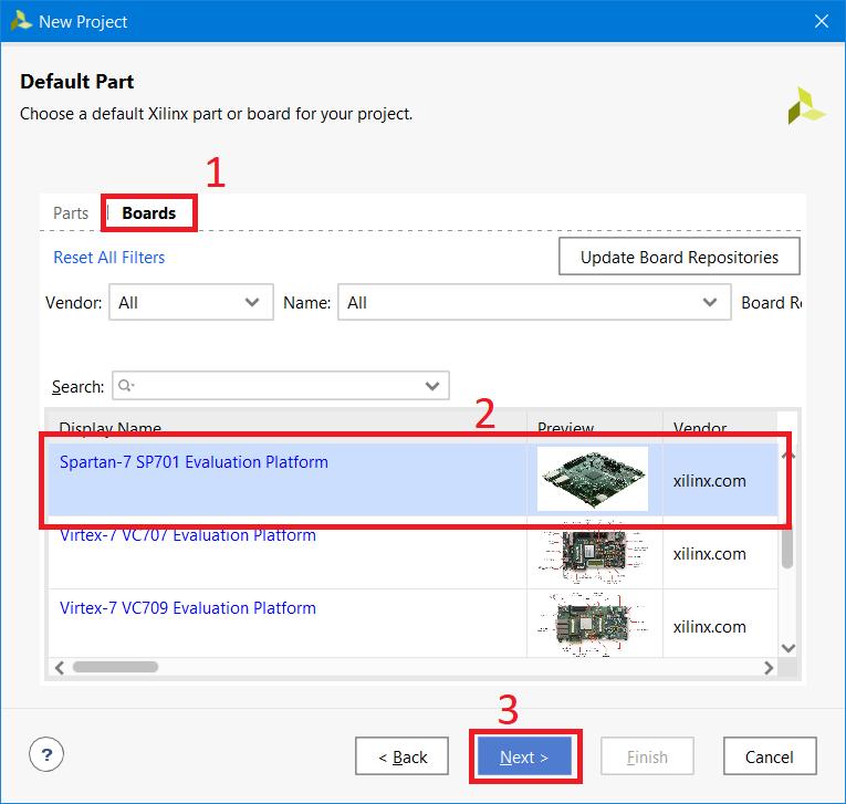
5. Go to the “Boards” tab (1) :: Find and select SP701 (2) :: Click “Next” (3)
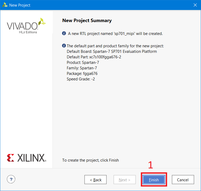
6. Click “Finish” (1)
Step 2: Install Licenses
In view of the fact that we will use IP Core, which require licenses, we need to generate and install them. The test project uses IP to connect both the camera (MIPI CSI-Rx) and the display (MIPI DSI-Tx), for which Xilinx offers a trial license for a period of 120 days.
PS: In the test project, the image output is duplicated to the HDMI interface, the presence of a display with the MIPI interface is not necessary, but a DSI-Tx license is required.
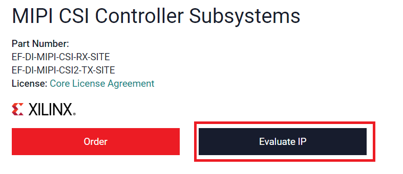
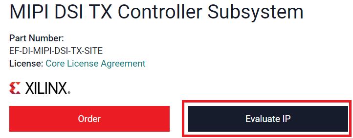
7. Obtain a license for CSI-Rx (camera connection) by clicking on the link and click on “Evaluate IP”. Then follow the instructions.
8. Obtain a license for DSI-Tx (display connection) by clicking on the link and click on “Evaluate IP”. Then follow the instructions.

9. Download the license files.
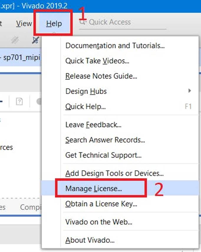
10. In the Vivado window, click “Help” (1) :: Select “Manage License” (2)
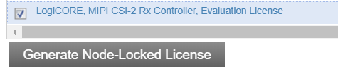
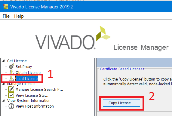
11. In the license manager, select “Load license” (1) :: Then “Copy license” (2). Select downloaded .lic licenses for CSI and DSI IP cores
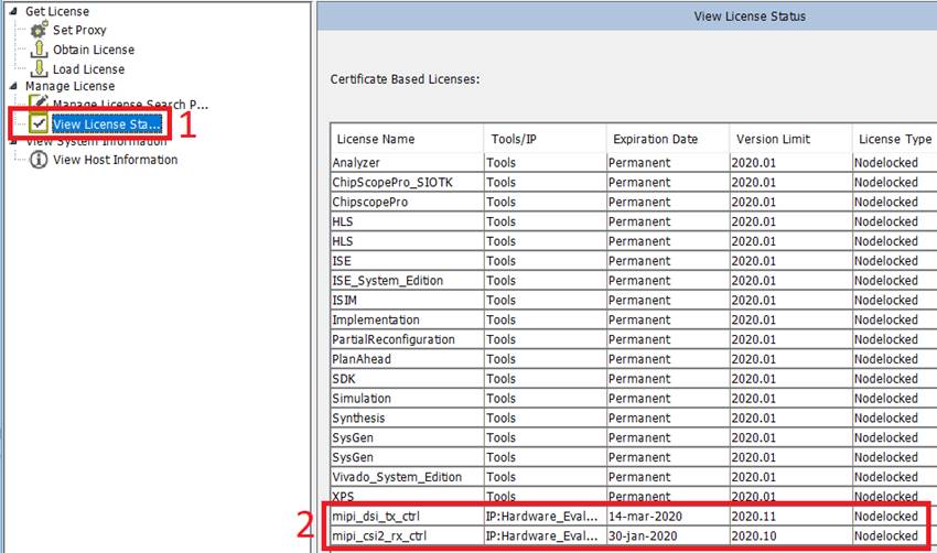
12. In the license manager, select “View License Status” (1) :: Make sure that the licenses are picked up correctly (2)
Step 3: Create a Test Project
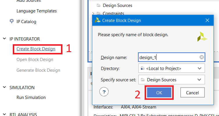
13. In Vivado, click “Create block design” (1) :: Click “OK” (2)
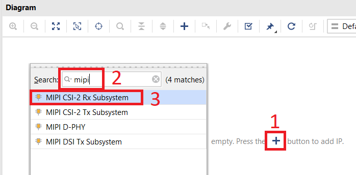
14. On the IP Integrator field, click “+” or “ctrl + i” (1) :: Type “mipi” in the “Search” field (2) :: Double-click on “MIPI CSI-2 Rx Subsystem” (3)
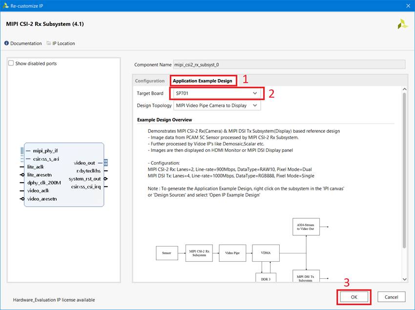
15. Right-click on the created IP (1) :: Select “Customize Block” (2)

16. Go to the tab “Application Example Design” (1) :: Select “SP701” (2) :: Click “OK” (3)
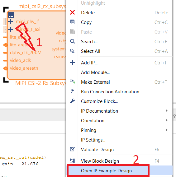
17. Right-click on IP (1) :: Select “Open Example Design” (2)
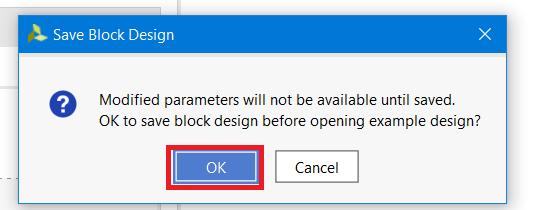
18. Click “OK” to save the project changes.
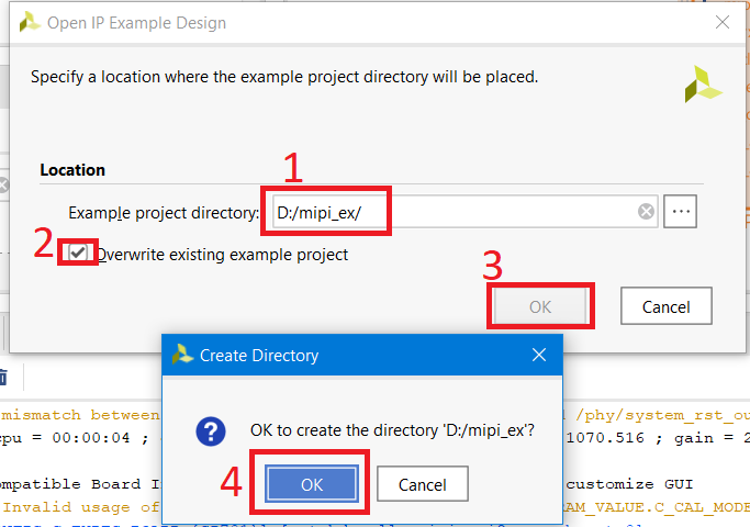
19. Specify the directory where the test project will be located (Note that for Windows users the path to the folder should be as short as possible, otherwise the path to the internal IP kernels of the project may exceed 260 characters, which will cause an error when creating the project) (1) :: Install the checkbox (2) :: Click “OK” (3) :: Click “OK” (4)
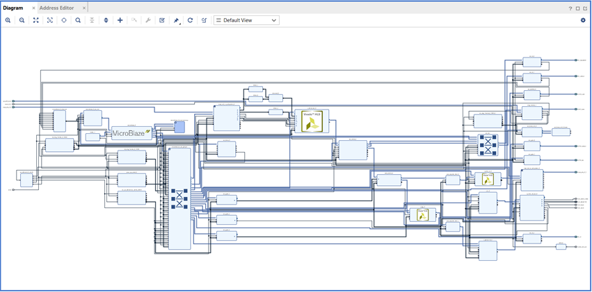
20. The test project will open in a new Vivado window. Wait until the creation of the project. It will take a few minutes.
21. In the test project window, click “Generate bitstream” (1) :: Click “Yes” (2)

22. Select the preferred number of simultaneously synthesized IPs (1) :: Click “OK”

23. Wait until the FPGA firmware file is created (bitstream)
Step 4: Setup and Connection
24. Connect the PCAM-5C camera to the MIPI CSI connector on the SP701 board
25. Connect the HDMI monitor and / or MIPI display to the SP701
26. Connect the uUSB cable to the SP701 board
27. Turn on the power of the SP701
28. Open a terminal application for the serial port (for example, Tera Term). Due to the fact that three different COM ports are recognized in Tera Term, we opened three different Tera Term sessions. The UART speed at which messages will be streamed has a speed of 9600 (check the IP uartlite settings in the test project)
Launch and debugging
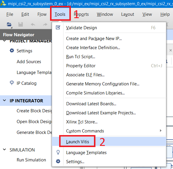
29. Launch VITIS from Vivado. Click “Tools” (1) :: Click “Launch VITIS” (2)
30. Specify the work directory. It is located inside the directory of the test project “mipi_ex :: mipi_csi2_rx_subsystem_0_ex :: SW :: xmipi_app” (1) in our case :: Press “Launch” (2)

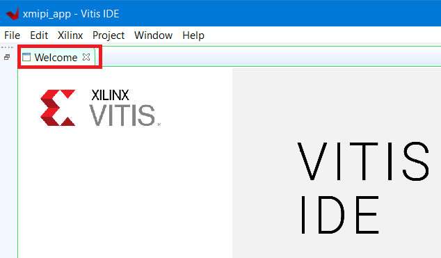
31. Close the “Welcome” tab in VITIS
32. Now we have access to the software component of our project, ie program for MicroBlaze software processor. Examine the code if you wish.

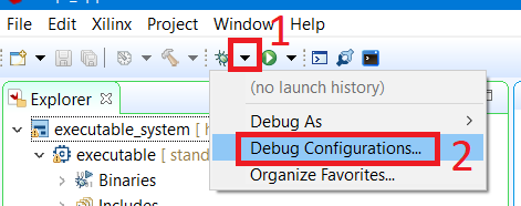
33. Click the arrow next to the bug icon (1) :: Click “Debug Configurations” (2)
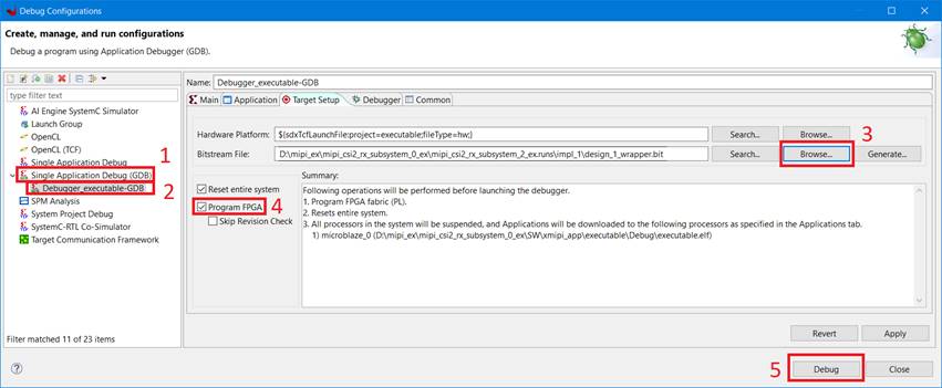
34. Double-click on “Single Application Debug (GDB)” (1) :: Select “Debugger Executable” (2) :: Specify the FPGA firmware file (.bit) created by Vivado (3) :: Install the checkbox (4): : Click Debug (5)
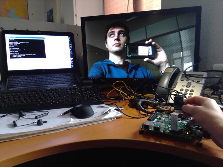
35. Press the start button and follow the instructions that appear in the Tera Term terminal

36. That's all (do not forget to remove the protective cap from the camera;)
Conclusion
As we have seen, creating a test project with a MIPI interface is quite simple. It took only VITIS / Vivado and the availability of appropriate hardware (boards and cameras). Almost all Xilinx IP cores have the ability to generate a test project, and in this article we demonstrated how to do this.