We continue to disassemble the software component of the MIRO platform. I would like to consider more specifically the software under AVR. Therefore, we will devote two parts to the issue. In the first, we describe the general structure of the library, and in the second, the implementation of some key class methods.
Table of Contents: Part 1 , Part 2 , Part 3 , Part 4 .
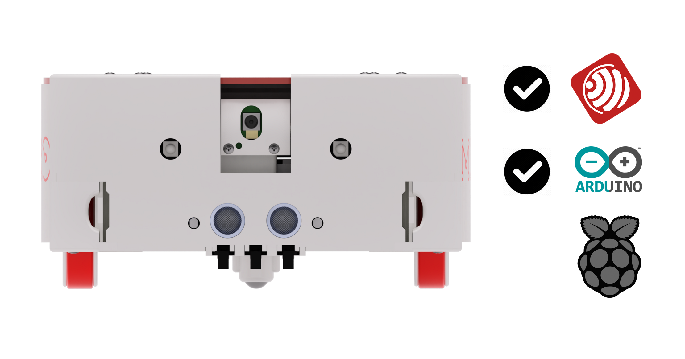
The software under ARDUINO turned out to be the largest of the self-written. In general, almost all the logic of directly working with actuators and sensors of the robot lies with the AVR. And at this level, API is implemented - a quick development software library for MIRO.
The API structure is described in the wiki section of the corresponding repository . So far, only in Russian. And now we will analyze the code in more detail. I will not intentionally give full class declarations, abbreviating it with the ellipsis "...", leaving only things that are significant at the moment.
In our software model, each MIRO robot consists of a chassis and a set of connected devices. When designing, it was assumed that the robot chassis - it will always be some kind of wheeled chassis - walking robots or robots that use some other principles of movement should be considered separately.
class Miro : public Robot { public: Miro(byte *PWM_pins, byte *DIR_pins); #if defined(ENCODERS_ON) Miro(byte *PWM_pins, byte *DIR_pins, byte *ENCODER_pins); #endif ~Miro(); ... };
The Miro class is a top-level class and describes the complete configuration of the robot. This class is the descendant of the Robot class, which describes only the most basic functionality of the robot.
class Robot { public: Robot(byte *PWM_pins, byte *DIR_pins); #if defined(ENCODERS_ON) Robot(byte *PWM_pins, byte *DIR_pins, byte *ENCODER_pins); #endif ~Robot(); Chassis chassis; void Sync(); int attachDevice(Device *dev); int dettachDevice(Device *dev); ... protected: Device* _devices[ROBOT_MAX_DEVICES]; byte _device_count; };
The designer performs the initial setup of the chassis pins and the initial values of the configuration of the robot.
The Sync () method implements the necessary operations for the chassis and for all devices connected to the robot, each step of the main loop () loop of the ARDUINO sketch. The Miro Sync () methods of the Miro class invoke the corresponding Sync () methods of the chassis and all devices connected to the robot.
The Robot class also contains a pointer to an array of devices connected to the robot, methods for working with this array (connect a new device, disconnect, find by index and name). Also, the Robot class contains an object of the Chassis class - the chassis.
But let's start with something simpler - with devices. Each device that can be connected to the robot, be it an LED, a sensor, or an actuator that does not directly relate to the chassis (trolley), is described by its successor class, which is common for all devices in the virtual Device class:
class Device { public: virtual void Sync(); virtual void setParam(byte pnum, byte *pvalue); virtual void getParam(byte pnum, byte *pvalue); virtual byte getPinsCount(); virtual char* getName(); virtual byte getParamCount(); protected: byte *pins[2]; };
The virtual methods setParam, getParam, getParamCount are associated with assigning, receiving, and determining the number of device parameters. The parameter can be any property: the brightness of the LED, the position of the servo drive, etc. The successor class of each device implements these methods in its own way. The purpose of the getName, getPinsCount methods, I think, is clear from the name. The newly encountered Sync method is a special method for non-blocking device control and automation of some device operations that must be performed regularly, each iteration of the main loop.
Let's now look at some more or less general implementation of the descendant class.
class MIROUsonic : virtual public Device { public: void Sync(); void setParam(byte bnum, byte *pvalue); void getParam(byte bnum, byte *pvalue); byte getPinsCount(); char* getName(); byte getParamCount(); void Init(byte trig_pin, byte echo_pin); void On(unsigned int max_dist); void On(); void Off(); int getDist(unsigned int max_dist); unsigned int getMesCount(); private: bool _isOn; unsigned int _mesCount; unsigned int _dist; unsigned int _max_dist; };
In determining the class of an ultrasonic rangefinder (above), in addition to the methods of the parent, there are also methods:
- Init - initialization;
- On and Off - turn on the device (rangefinder);
- getDist - returns the distance measured by the range finder;
- getMesCount - returns the number of measurements taken since the device was turned on.
To store the internal state of the device, the following fields are used:
- _isOn (TRUE - the device is turned on, controlled by the On and Off methods);
- _mesCount (stores the number of dimensions used in the getMesCount method);
- _max_dist - maximum required distance for measurement *;
- _dist is the actual measured distance.
About maximum measuring range
* It is known that the widespread HC-SR04 according to the passport is capable of measuring distances up to 4 meters. However, the measurement method itself involves waiting for the return of the ultrasonic signal, followed by encoding the duration in the signal on the Echo line. And in fact, if the user definitely does not need to measure distances in the range up to 4 meters, but enough, the range, say 1 meter, then you can wait 4 times less for the reflected signal. The rangefinder itself generates a signal on the Echo line as soon as it receives it and performs modulation. Those. this may not affect the length of the period between adjacent measurements, but the duration of a single measurement in this way can be reduced.
And now for the explanation of the Sync method. If the device has the state _isOn == TRUE (on), then the measurement cycle itself will be performed in the Sync method, and the measurement result will be recorded in the _dist field. In this case, when you call getDist, the method will immediately return the value recorded in _dist, there will be no measurement cycle. If _isOn == FALSE (off), the measurement cycle, on the contrary, is performed only during the call to getDist, nothing will be measured in the Sync method. It is assumed that the programmer will call the Sync method of the entire robot, which in turn will call the Sync methods of the same name of all devices connected to the robot and an object of the Chassis class (chassis).
Of the devices in the API, only those things that MIRO has are currently implemented: LED, ultrasonic range finder, photo-resistive light sensor, servo drive, line sensor.
Lightly touch the Chassis. This class implements the "abstract cart" of the robot. It contains methods that allow you to control movers.
class Chassis { public: Chassis(byte *PWM_pins, byte *DIR_pins); #if defined(ENCODERS_ON) Chassis(byte *PWM_pins, byte *DIR_pins, byte *ENCODER_pins); #endif ~Chassis(); void Sync(); float getVoltage(); int wheelRotatePWMTime(int *speedPWM, unsigned long time); int wheelRotatePWM(int *speedPWM); bool wheelIsMoving(byte wheel) {return this->_wheel_move[wheel];} byte getWheelCount() { return WHEEL_COUNT; } #if defined(ENCODERS_ON) int wheelRotateAng(float *speed, float *ang, bool en_break); unsigned long wheelGetEncoder(byte wheel); ... #endif //ENCODERS_ON private: float _vbat; //Battery volgage bool _wheel_move[WHEEL_COUNT]; char _wheelDir[WHEEL_COUNT]; byte _wheel_PWM_pins[WHEEL_COUNT]; byte _wheel_DIR_pins[WHEEL_COUNT]; void _init(byte *PWM_pins, byte *DIR_pins); #if defined(ENCODERS_ON) byte _wheel_ENCODER_pins[WHEEL_COUNT]; bool _wheel_sync_move; float _wheelAngSpeed[WHEEL_COUNT]; float _wheelSetAng[WHEEL_COUNT]; float _wheelSetAngSpeed[WHEEL_COUNT]; ... #endif //ENCODERS_ON };
If we consider a cart without encoders and generally without feedback, then there are simple control methods for this using a PWM signal. If there are encoders in the trolley, the class becomes much more complicated. To simplify the life of the user, methods such as appear in it:
- wheelRotateAng - wheel rotation at predetermined rotation angles with given angular velocities;
- wheelGetPath - returns the length of the path traversed by each wheel;
- wheelGetLinSpeed - returns the current linear speed of each wheel;
- wheelGetAngSpeed - returns the current angular speed of each wheel;
- wheelGetEncoder - returns the number of responses of each wheel encoders.
And a number of auxiliary methods. As well as a method of calibrating propulsors. But in more detail the key methods of the Chassis class will be considered next time.
Looking a little ahead, it is in this place that it will be appropriate to note that this entire Miro library can be easily adapted or supplemented with any other robot with a two-wheeled differential motion scheme. And with a certain effort - and to other propulsion and steering configurations. In the case of the differential circuit, you just need to correctly describe the config.h configuration file. And without any RPi. For example, in less than an hour, we launched everything on such little ones for our regional BlackMirrorCTF-2019 cybersecurity tournament at our university ( link ).
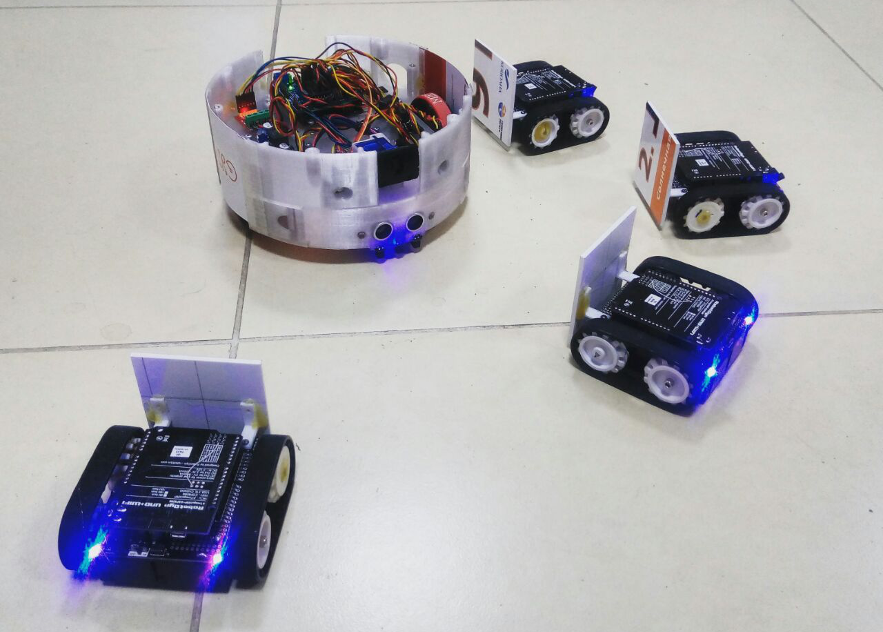
The robots had an interface for access via Telnet and a command system for remote control. The document with the command system was somewhere hidden or encoded. Participants scanned the IP addresses and open ports on the robots themselves. With a successful connection, the robots issued an invitation, and the participants understood that they had "entered." Well, then the teams brought the robots along the highway to the finish line. Initially, they wanted to make the entire track with robots somewhere in an isolated room with an IP camera installed, but the organizers had some problems with the IP camera and lost some of the charm.
That's all for now. It is possible that in the course of development, the program model will undergo changes. By the way, it has recently been slightly modified, after the code looked a little more experienced OOP-box.
Ahead of the fifth part - let's talk about encoders, angles and calibrations.