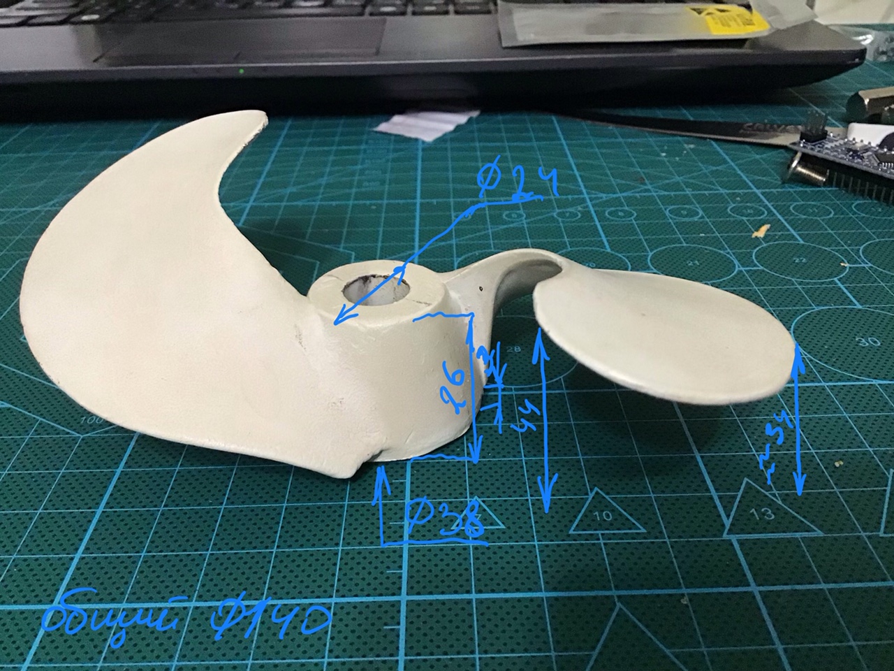
Uncle is already old and far from PC and the Internet, but he loves fishing very much. Of course, the first thing I asked him about buying a screw, but he said that he didn’t find one that he needed (he didn’t find it). He needs a two-bladed, non-hook type propeller. He brought me as an example a screw purchased over the Internet in some remote region. But this screw turned out to be in the opposite direction of the blades and slightly smaller than we would like to put on a new engine.
Well, I didn’t want to upset my uncle, so I had to take on this project ... The task was as follows: to make a two-bladed screw from aluminum, scaled by the outer diameter from 140mm to 180mm, and rotate the direction of the blades in the opposite direction, that is, to make a mirror version relative to the sample.
The implementation was as follows: digitize the sample, make the 3D model mirrored, fit it to the required size and start production on the CNC machine.
Immediately the question arose about digitization, of course, it would be the easiest solution to use a 3D scanner, but the price tag translates this solution into a category of complex ones. There remains the option of doing everything by hand (there was not enough imagination for more).
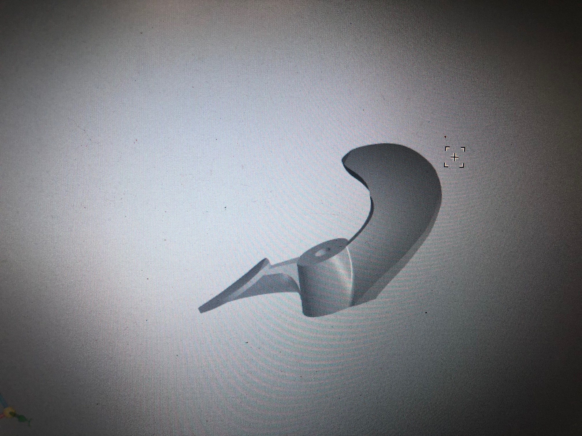
He sat down at one of the programs for 3D modeling and began to create. The model was obtained the first time, quite good, but the profile of the cross section of the blade is straight, not aerodynamic.

At this stage, I decided not to bother with drawing, since this model still somehow needs to be made of aluminum. It is not so easy and cheap to find a billet of an aluminum alloy of the desired diameter and height, and my machine tool is rather weak for metal processing, and there is no desire to process such a bulk billet with 0.1 mm removal.
In general, it was proposed to make a model of wood (or something similar), modify it by hand, if necessary, and then give it to a foundry, where according to our model the final part will be cast from aluminum. The price tag voiced more or less satisfying.
Then he began to think over the manufacture of the model on the machine, since processing was required from two sides. I reduced the scale of the model so that it fits into my workpiece.
In ArtCAM, he created the G-code, and the center of the workpiece was taken as the origin. As a blank, I took a piece of a pine board 50 mm thick, found the center in it and fixed it on the machine, from the sides rested with clamps.

I started roughing with an end mill with a diameter of 6 mm, at the end I changed the mill to a finishing conic with a radius of 1.5 mm. I spent the finishing work, after which some shortcomings appeared on the work of the machine (but there will probably be another post about it).
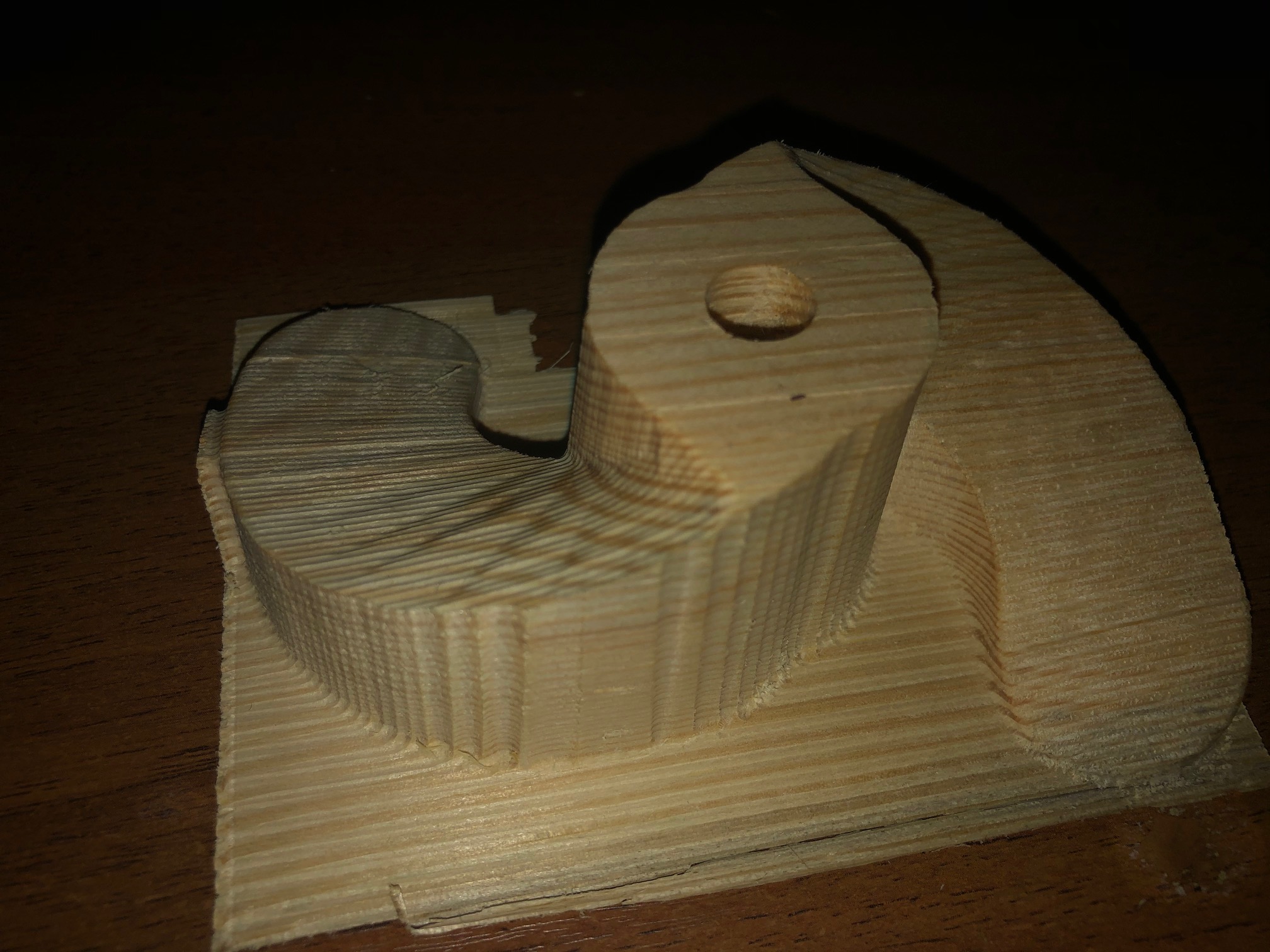
Oddly enough, the first side was surprisingly good. Now he had to turn the workpiece over. To do this, the part glued to the thin plywood with the machined side, and screwed it to the machine in the same hole with the initial coordinates. He pinned the plywood with plastic clips.

Started processing: draft, finishing. Everything went well, the only one slightly bent the blades closer to the tips, since there is the thinnest place. On a large model, this will no longer be, you may even have to glue the racks for greater rigidity.
I summarize: before that I had no experience in double-sided processing, I think that for the first time it turned out to be quite a good craft, not without small shoals of course, but where without them. Next, work on a full-fledged model will be done, but first I want to finish the 3D model and the machine, since some shortcomings were identified during the work.
PS: Each of us is an artist and sees in his own way. I did as I saw. I am sure that there are a lot of options to do it somehow differently.
Thank you all for your attention!