There are at least two approaches to creating 3D models. In one of them, the most popular, objects consist of many polygons. In the other ( freeform surface modeling ) - from NURBS surfaces that are defined by curves (splines).
Each approach has its advantages and disadvantages, which are largely similar to the differences between raster and vector 2D graphics. A lot of articles are devoted to the features of working with polygon modeling software, but as far as NURBS modeling tools are concerned, here, in my opinion, the situation is more complicated. Most of these articles are either tutorials on creating specific objects, or are intended more for software creators than for its users and are full of terms like “weights, T-points, n-th order curves,” etc. I’ll try to go through the middle .
Creating objects from NURBS surfaces is used in areas where accuracy plays an important role - both by itself and its preservation when editing an object. This is especially important in the manufacture of parts on CNC machines, which is why this approach is widely used in CAD.
However, accuracy is not the only reason for rejecting polygons. NURBS modeling is very widely used in industrial design, architecture and jewelry. If you look at well-known modern buildings, you will notice that they are a combination of shapes converging into each other - either recognizable geometric primitives, or complex, clearly mathematically defined, surfaces. The same applies to car bodies, household appliances, as well as various rings, necklaces (especially the “organic” look), etc.
Often these forms are quite recognizable and are due to the typical capabilities of the software for NURBS modeling. In other words, often the design is determined more by the specifics of the software used than by the ideas of the designer.
In this article, I want to use the Rhino 3D package as an example to focus on some features and problems specific to this approach.
Here you must immediately retreat. The fact is that working with NURBS surfaces can also be very different.
We will consider two ways - the standard Rhino functionality and the T-Spline functionality, which is a popular plugin for Rhino and, in fact, is an editor inside the editor - with its own representation of surfaces / bodies and its own ways of editing them.
First, let's look at a few primitives created using three different approaches. Next I will call them “mesh” (polygonal), “rhino” (Rhino NURBS) and “tspline” (T-Spline NURBS). Yes, polygon modeling in Rhino is also possible, albeit in a very stripped-down form.
Three cylinders, spheres, cubes, curved surfaces are depicted here.

Of course, directly comparing one with the other is not entirely correct - in particular because the vertices of the polygons and the points defining the spline are far from the same thing. However, some useful points can be clearly observed here.
For example, in the Rhino variant, a sphere is one curled surface (where the line is thicker - the place of its connection).
Cylinder - three surfaces: a twisted wall and two round “covers”.
The Rhino cube is somewhat similar to mesh - it consists of six flat surfaces (it’s just that the fact that they are flat is just a special case — they could be concave as well).
There is clearly something strange in the T-Spline version - the cylinder looks like a barrel, and the cube looks like a sphere. And the surface, if you look closely, has rounded corners. In fact, it seems that they are trying to pull off the inflated ball with hoops. And in order to get closer to the required clear form, more “hoops” will be needed. But we will come back to this. You can also notice that T-Spline has no seams.
C Mesh is understandable - it is clear that curved surfaces, with a small number of polygons, are not very smooth. Which is not news, of course. But with the cube, everything is great.
Now let's try to distort all the objects in a similar way, if possible, by pulling the corner:
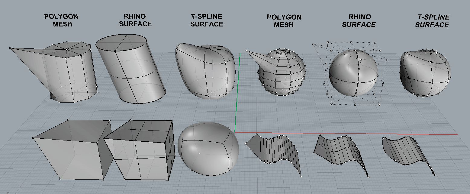
The reaction is clearly different. Mesh objects reacted most sharply than all, Rhino turned out to be more lazy and plastic, well, and T-Spline in general are soft-body samples.
Got a general idea, now let's move on to the specifics.
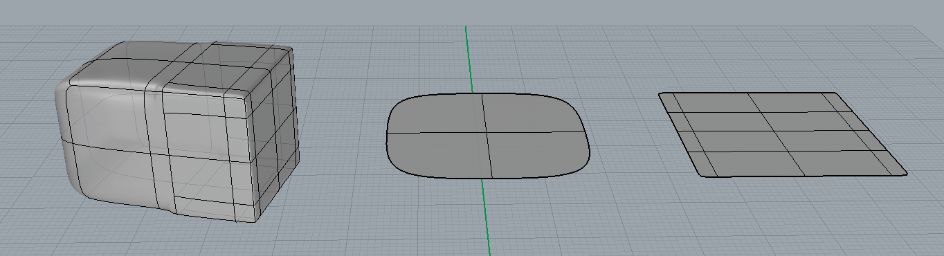
Flat surface in Rhino
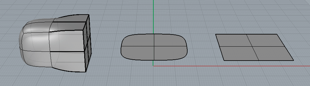
In Rhino, you can draw a curve and use one of the PlanarSrf, ExtrudeCrv, EdgeSrf commands (there are other options) to get a plane bounded by a certain curve:

It seems that the result (with the exception of the form) is everywhere the same. But this is not so - in the first case, the PlanarSrf team actually just took the rectangle and hid everything that goes beyond the curve. This process is called trimming. Below you can see the result of the Untrim command that removes the trim:
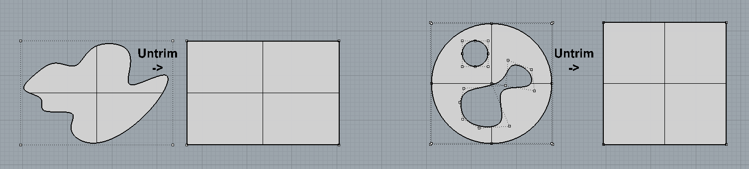
This difference is significant, because often objects (and holes in them) consist of larger cropped surfaces and behave accordingly:
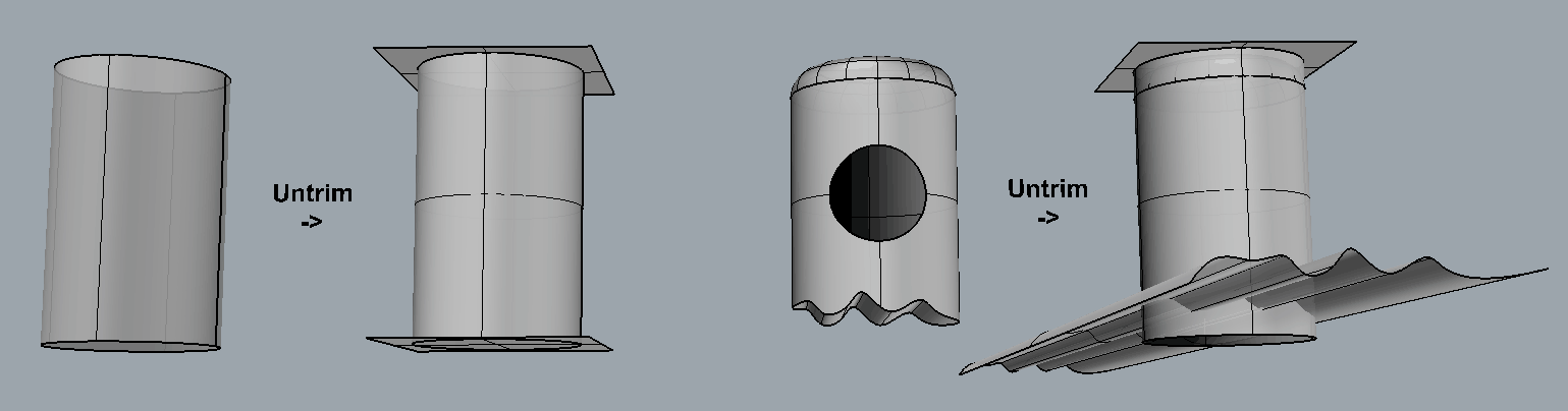
Often when performing operations on such objects, problems arise at the joints of surfaces. For example, here is a fairly typical situation with the formation of holes during the chamfering operation (the so-called “naked edges” are highlighted in color):

And another example:

To eliminate these kinds of problems, you have to do untrim and manually create new curves for cropping, followed by fitting them for joining, because if they are not joined correctly, we won’t get a solid body (by joining with Join).
To avoid unnecessary work, it is necessary to think carefully in advance what will be done and how, for when a problem suddenly arises, it turns out that it was laid many steps back and it is already problematic to return to that stage.
Simply put, in Rhino there is no easy way to edit complex surfaces and their bodies. This is a significant flaw in working with Rhino, which is partially fixed in T-Spline.
Flat surface in T-Spline
Now let's try to draw a flat surface in T-Spline. I must say right away that getting a plane bounded by a particular curve is as simple as in Rhino - you can't. More precisely, you can, but its topology will be so (terrible) that you can use it only in some special cases.
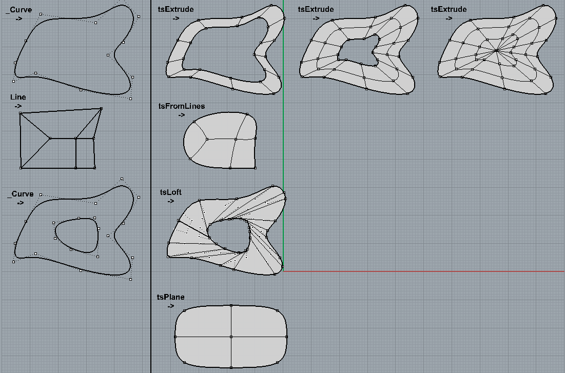
In the first case, the t-spline object is formed by extrusion of the curve. Note that the edges are formed where there were dots on the curve (in other words, not all look-like curves will be equally useful for a particular task).
Also, there is a problem of a hole in the center, about which below. Here, the hole is simply disguised - it has a zero size (the coordinates of all the points that define its edges coincide), but in practice this is a very bad situation. By the way, the regular tspline sphere mentioned in one of the previous pictures was also made - in fact, it is not a solid body and has holes at the poles. But the quadball, although topologically closer to the cube, but looks like a sphere and, moreover, solid. So everything is complicated and mysterious.
In the second case, the framework of the lines is taken as the basis. This method allows you to get a good approximation to the desired form and at the same time, which is very important, gives a sane topology (in fact, you completely specify it yourself). However, the relationship between lines and the resulting surface is very unobvious even in simple cases.
The third case is an analogue of Loft from Rhino.
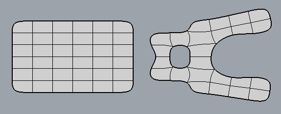
In the fourth case, the plane is created immediately - with the tsPlane command. You can set the number of faces horizontally and vertically. Taking such a plane as a basis, then removing the excess and moving the rest - you can get a rather complex figure with a good topology:
Returning to the issue of holes
There is a _tsFillHole command that automatically closes them. However, the result of her work is poorly predicted and satisfactory only in some very simple cases (such as a hole in the figure above).
In most cases, holes have to be carefully and carefully repaired - either by welding nearby vertices with the tsWeld command, or by creating edges between existing vertices with the _tsAppend command:
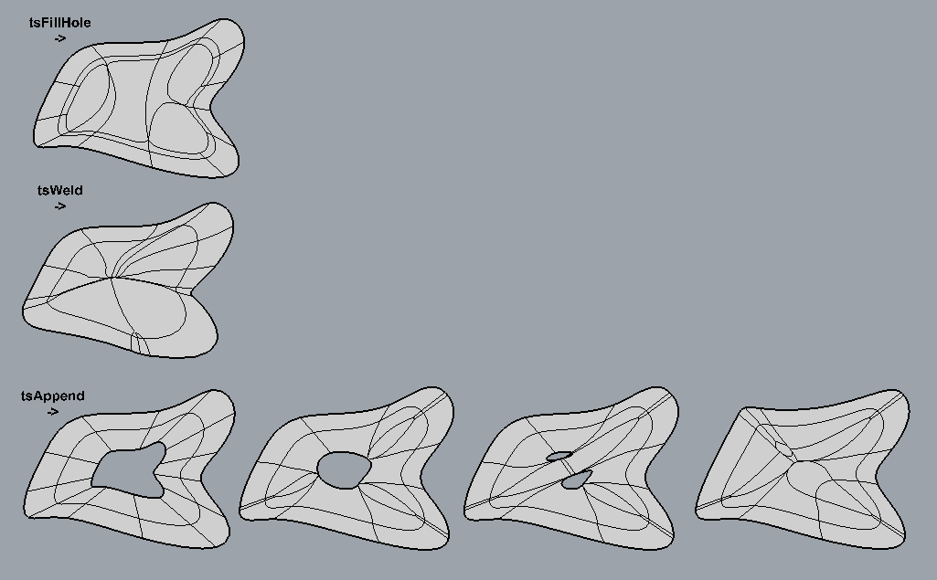
As you can see, if you approach “head on”, in all cases the result is terrible. Not only is the topology such that it has no practical application, but also the shape of the external borders has been distorted. And, although all this can be corrected, the error here is in the very way that the surface was created - it will be more difficult to correct here than to do it again. For this situation, tsFromLines would be much better (by the way, it reminded a famous picture with a web of stoned spider and sober):
Curved surfaces and solid bodies in Rhino
What is the difference between a solid body (solid or closed polysurface) from a surface (surface) or several connected surfaces (open polysurface)? Oddly enough, solid bodies may not differ in appearance from just surfaces. The real difference is the lack of holes. All surfaces forming a solid body should be tightly joined (Join) without any gaps. In this case, the object will be considered closed (rather than open) polysurface. Of course, there is the concept of tolerance and it can be changed by settings so that a clearly visible gap will be considered the absence of a gap. But this is already an emergency situation and you should not go along this path.

A curved surface can be obtained in the same way as a flat one - by extrusion of the curve, as well as in several other ways:

Let's take a simple example - a key cap. This is where Rhino works great. For convenience, we will insert a picture using the PictureFrame to immediately see what, where and what size should be approximately:
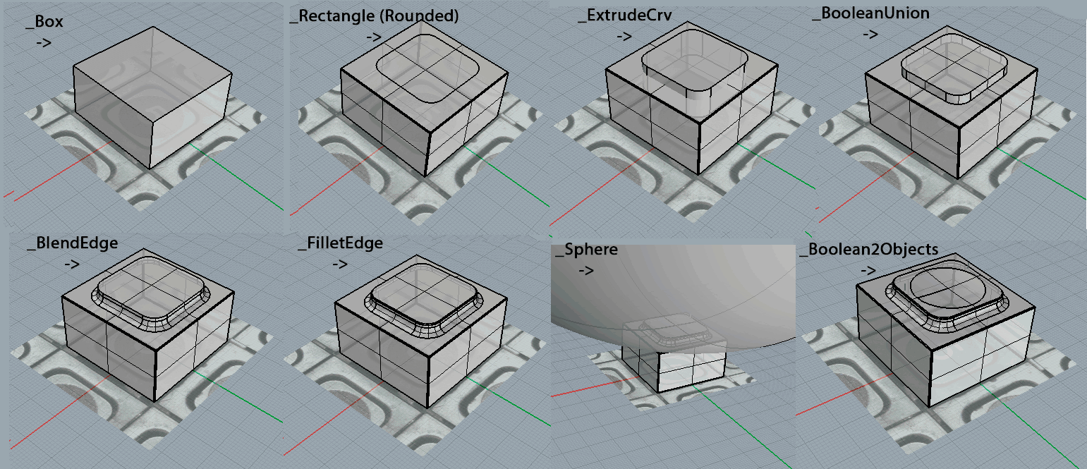
Here, everything that was taken as a basis is standard. Primitive parallelepiped, extruded rectangle with rounded edges on top. As a result, the subtraction of the sphere (to obtain a depression) and all subsequent rounding of the edges worked correctly.
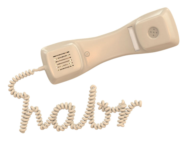
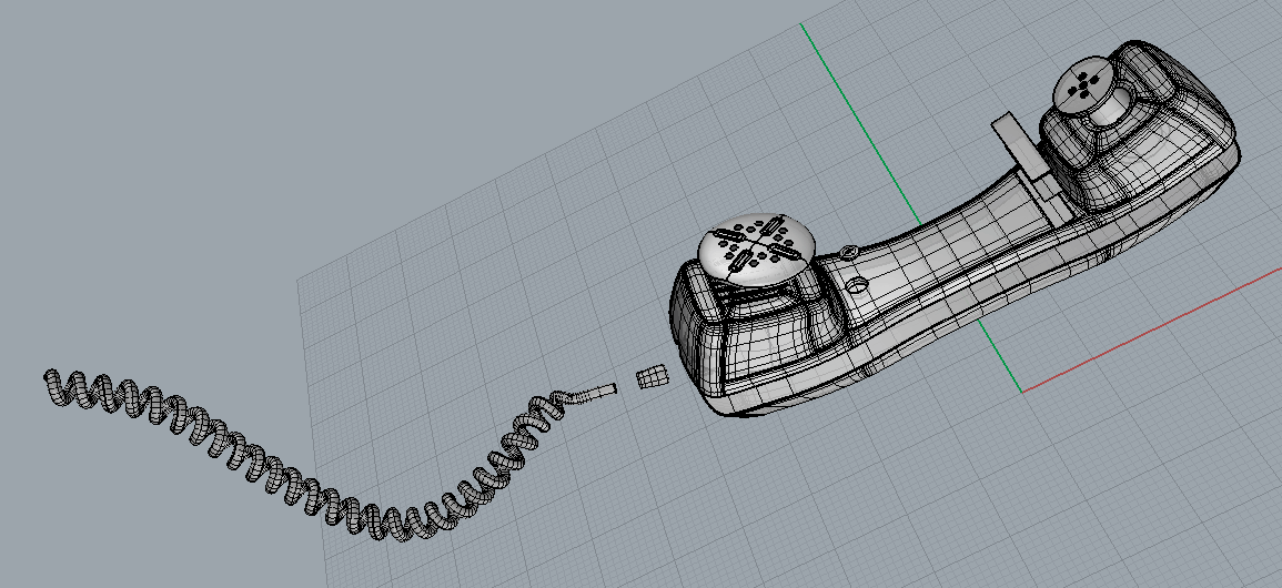
Now let's take a more complicated option - the handset and try to portray it without hesitation (usually at first they do just that, after which they are disappointed in the tool).
Option one, via CreateSolid:

Those. circle the contours with curves, turn them into surfaces by extrusion, then use the CreateSolid command to create a body limited by the intersection of these surfaces.
It seems that at first everything is going well, and most importantly simple. The problems begin when we want to make the tube rounded edges.
There is a Fillet command for this. Firstly, it is quite difficult to make exactly such roundings as needed, but it won’t even go into it. We do it primitively - select the edges and radius. It worked, but on the one hand an obvious artifact is visible (in fact there are more of them, just the others are less noticeable). Upon closer examination, it turns out that in this place the surfaces are far from ideal, but were, as it were, crumpled. Accordingly, Fillet worked inappropriately. Strange, because the original curves were quite smooth and neat in appearance. It turns out that this is far from enough!
The causes of the problems are different. It may turn out that the curve along which the edge of the surface is cut has small loops, kinks and other charms.
As a result, here we will be forced to roll back, make this curve Rebuild / Refit, or even recreate the body again. There are problems caused by the operations themselves, as a result of which new curves and surfaces are formed.
Maybe you can make rounding right away? Well, you can. For example, using Loft and NetworkSurf:
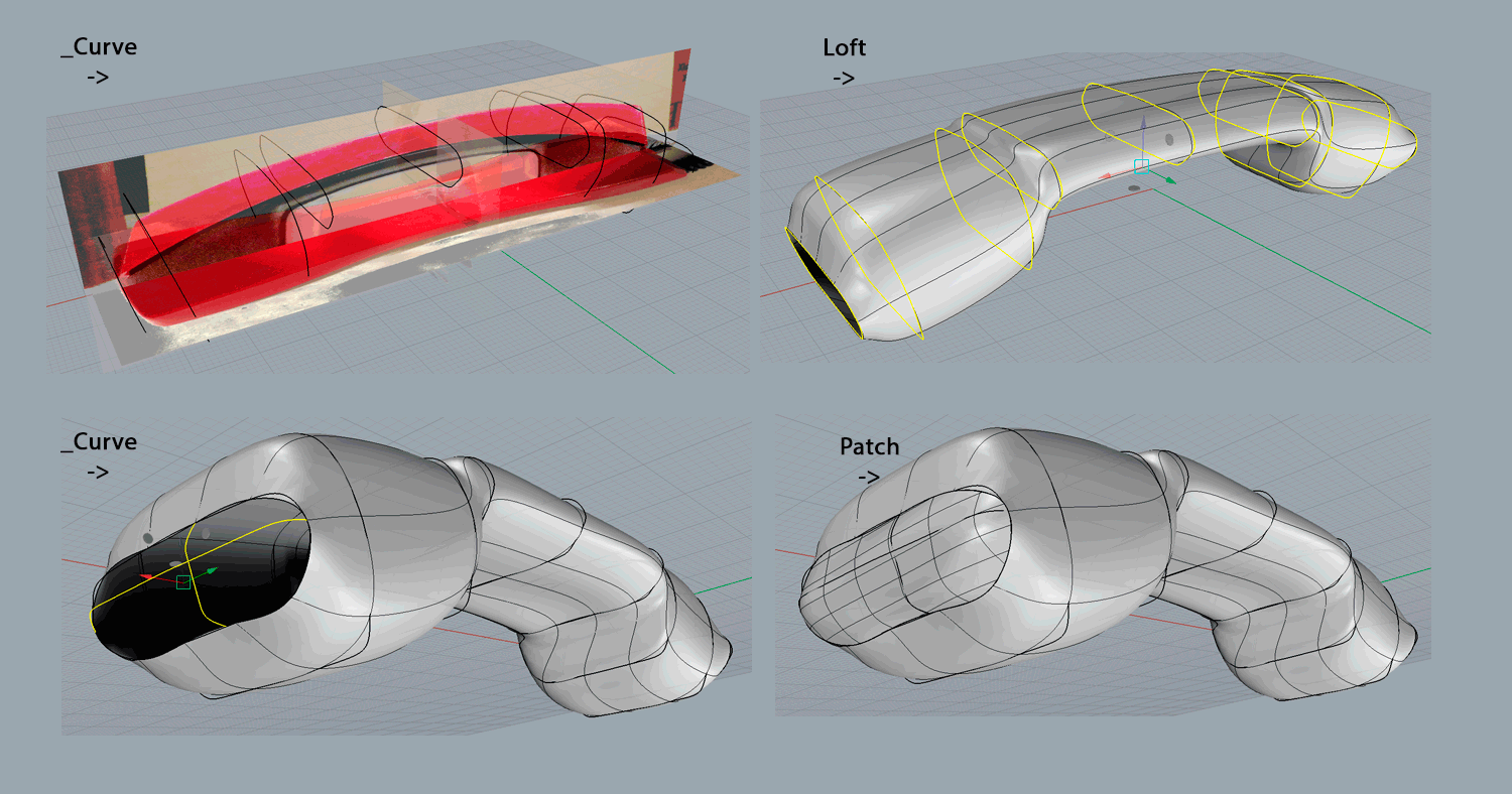
Here, a different approach is used — several curves reflecting the shape of sections in several places of the body. The Loft team immediately builds the body from these curves. Everything would be fine (only the curves, of course, need more to make the surface more accurate), but there is a problem with holes at the ends, which are very difficult to close correctly (in this case, Patch was used).
A more complicated option is the NetworkSurf team.
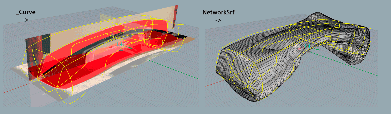
In this case, the curves are taken not in one direction, but in two or three. In theory, everything should turn out great. In practice, all the curves should be located relative to each other in a strictly defined way - somewhere intersect, somewhere not. These rules are very unobvious (and not formally described). Therefore, with a small number of curves, as in this example, the team passes, but a little more - no longer. Moreover, there is no meaningful diagnosis - just the command cannot be executed. What exactly is wrong is very difficult to find out.
Any approach, of course, does not exclude the unification of several bodies into one, cutting off some parts, transformations, etc. But the problems laid down initially, at later stages, rarely can be well fixed.
The general moral is this: in Rhino you can create a complex neat body. But 90% of success is determined at the very beginning of the work - at the stage of choosing the approach that is successful for a given concrete body and when creating the main curves. Reluctance to do this is one of the reasons why T-Spline products have appeared ...
Curved surfaces and bodies in T-Spline
There will be less variety in T-Spline. The reason is that it is easier, in comparison with Rhino, to fix something already done. For this reason, it is convenient to take some kind of primitive and simply edit it to the desired form.
Similar to the situation with the plane, you can use tsFromLines, setting the grid of lines not in the plane, but in 3d. Although, this is even more complicated than in the 2D case.
In some situations, it’s convenient to first make some kind of Rhino surface or even import a Mesh, then convert it to T-Spline, and then edit it. But this is only possible in fairly simple cases. In addition, in such a situation, you cannot influence the final topology, and the prospects for further editing directly depend on this.
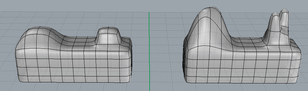
As an example, consider creating the same handset in T-Spline. Take the Box primitive and edit it:

First, bend using the Bend. The next logical idea would be to deform its middle part (as in the crossed out picture), but I must say right away that this is a bad idea. In this particular case, it will not work in such a way to make accurate smooth bends. So let's do it differently - first remove some of the faces, and then close the holes with tsAppend.
You may notice that this particular tube is a symmetrical object. We can greatly simplify our work by pointing this out to T-Spline with the tsSymmetry team. There are two approaches: either designate the axis of symmetry if we already have a symmetrical object (not our case, because the tube just seems symmetrical - for T-Spline the halves will still be slightly different). Or create a symmetrical object. To do this, delete half the tube and indicate that the plane of symmetry passes along the line of removal. From now on, all actions on one half will be reflected on the other (see the third picture):

By the way, note that during the process in some places the extra edges were removed. The smaller they are, the easier it is to make a smooth, even surface. On the other hand, the more ribs, the more detailed changes can be made. In the process, the ribs in the right places are then removed, then added - depending on the situation.
T-Spline: sharp boundaries
Unlike Rhino, in T-Spline it is difficult to make sharp borders or corners. There are two fundamentally different approaches to solving this issue. One is the creation of so-called creases (folds). In this case, T-Spline explicitly make it clear that a particular edge must be sharp
In practice, this approach has many disadvantages. In particular, this sharpness cannot be controlled in any way, which means that in the end, you don’t have to do fillet after converting the surface to Rhino. With a very high probability in the process there will be problems that will be difficult to eliminate.
Another approach is to control the curvature with additional edges and change the distance between them. Here, too, there are difficulties - for example, at an angle where three edges meet, it will be difficult to obtain the required radius of curvature. In addition, a very sharp bend (so that later, when converting to Rhino, one “rib” is obtained) will not be possible at all. And that means that you can do something with it, for example, round it, then you can hardly do it later.
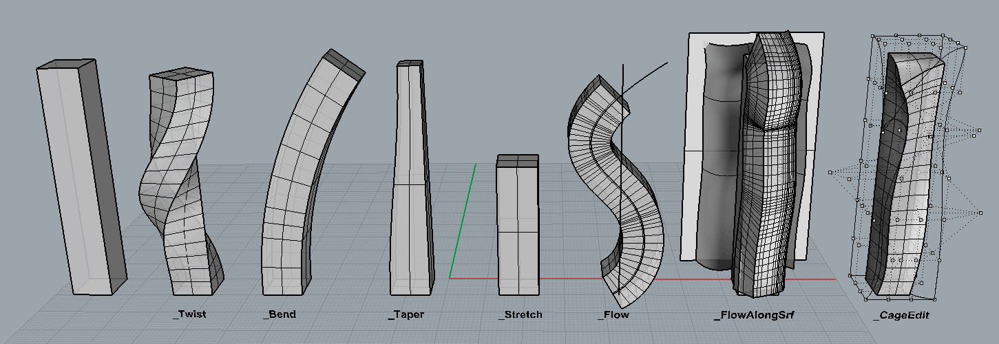
Surface Transformation in Rhino
Rhino has a fairly rich set of commands that allow you to tilt, bend, twist and even distort the surface in a complex way. The only thing to consider here is the poor reversibility of such transformations. If you bend the surface in one direction, and then bend back - most likely you will get another, more complex surface. With multiple and / or complex transformations of bodies consisting of several surfaces, problems will arise at the joints of these surfaces.
Surface Transformation in T-Spline
In T-Spline, everything is much simpler. Most often, you don’t even need to use any special commands - simply selecting and moving / rotating / scaling points, edges or faces, including in combination with radial symmetry, gives you almost everything you need.
There is no problem of irreversibility - the points can always be manually returned back, even if this requires painstaking manual work.
As for the use of the above-mentioned standard commands for Rhino (_Twist, _Bend, etc.), there is an important nuance - the effect depends on the editing mode. If a tspline object is selected as an object, then applying transformation commands to it will lead to premature conversion of the object from tspline to rhino, which is completely unacceptable. But if the mode of control points, edges or faces is selected, then, in fact, the points will undergo transformations:
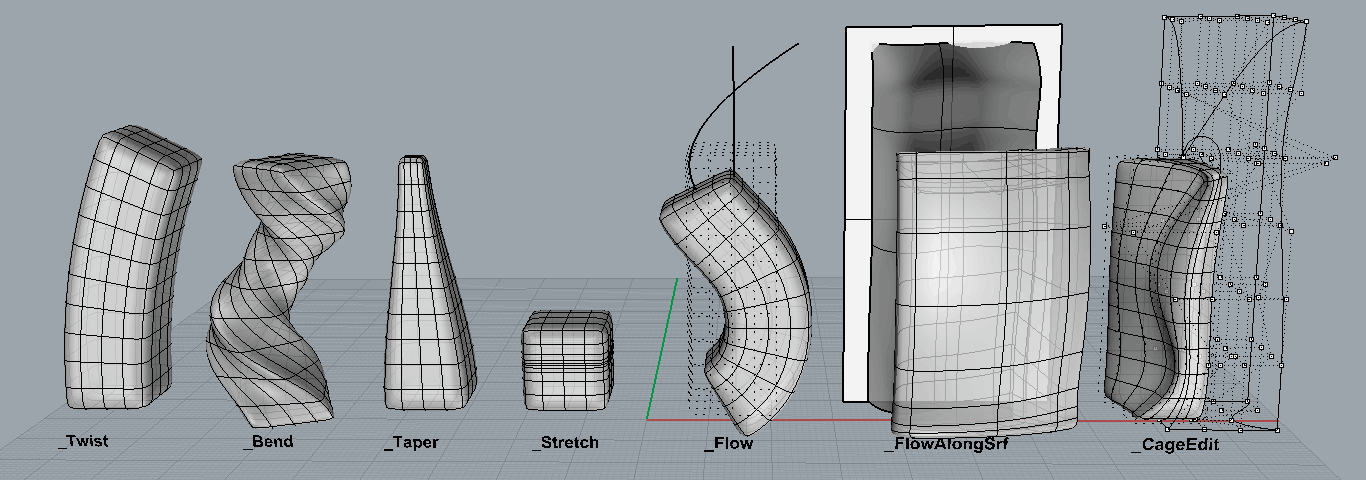
In this case, only part of the object can be selected for transformation:

Features of Rhino: history
Although Rhino does not allow detailed editing of the geometry of finished surfaces, it does have a history mode, from the moment it is turned on, the operations performed are remembered. For example, if you created a surface based on one or more curves with history turned on, subsequent movement of the points of these curves will lead to a change in this surface. This mode, however, has a number of limitations - even a simple movement of the surface turns it off, recalculating complex surfaces at each point shift requires a lot of computing resources, etc.
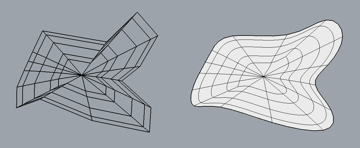
Features of T-Spline: extrusion and stars
Although the Extrude team exists in Rhino, it works differently in T-Spline. Here, the objects are composed of many faces to which extrusion can be applied selectively.
On the left side of the object, four faces are raised up without extrusion. On the right - with extrusion. Please note that during extrusion, special points arise where five edges meet - stars. Similar points (of three edges) can be seen at the corners of the object.
It is difficult to control the curvature in such places - folds, wrinkles, etc. can easily appear there, therefore, stars should be avoided, if possible (and if this was not possible, at least minimize the number of converging edges). Stars can appear on their own - when removing faces, plugging holes, extruding faces, etc.

So T-Spline or Rhino?
In general, the approach is as follows:
Rhino:
- If the simulated object has sharp or sharp edges / edges (for example, a gem after cutting)
- If it has a complex configuration, which must be precisely repeated (for example, it must correspond to the drawing)
- If the object has small (relative to the object itself) parts, especially holes or cylinders of the correct shape, and especially if there are many of them.
- If the object consists of several dense adjacent parts
T-Spline:
- If the simulated object has smooth, including smoothly transitioning into each other shapes without sharp edges and transitions. Usually similar forms are called "organic"
- If you want to simulate imperfections (roughness, inaccuracy) of faces and surfaces. In Rhino, this is very difficult to do - even with additional measures when rendering, the object may seem too right (and therefore not realistic enough).
- If the shape of the object is supposed to change in the future
However, as already mentioned, often the workpiece is made in T-Spline, converted to Rhino surface and finalized already in Rhino.
More on the relationship between Rhino and T-Spline
A fairly typical scheme of work, if we are talking about creating a model according to the model, is as follows (provided that T-Spline is applicable - that is, the forms are smooth):
1. If there is only an image of an object from an incomprehensible angle, then either start by looking at the image right away, create a surface in T-Spline (from primitive or extruded curves) or, if it’s convenient, first create a general shape in Rhino, and then transform the surface in T-Spline and there you continue to edit.
If there is at least one image strictly from above, from below, from the side, then insert it using a pictureFrame and do all of the above along its contours.
If you already have a polygonal mesh model (for example, from a 3d scanner), then first try to convert it immediately to rhino or t-spline model. Most likely will not work. Then you can create a model in T-Spline guided by the vertices of the polygonal model - as if pulling the created tspline surface onto the mesh contours.
Up to the point that you directly create faces on the surface of the polygonal model by tsAppend and then align the points of the resulting T-Spline surface with the polygonal one.
2. Convert the finished T-Spline surface to an Rhino surface. This should be done when you are absolutely sure that it is completely ready and can no longer be improved in T-Spline (there will be no return trip).
3. Thoughtfully look at the surface obtained by Rhino and notice that it actually consists of several surfaces. Stitches are your future pain. Try not to perform any operations close to them, such as holes, cutouts, etc. It is highly likely that subsequent rounding and chamfering at the edges of the cutouts located there will be problematic.Up to the point that you have to modify the original T-Spline surface (which you prudently saved)
4. Do everything that Rhino allows, but not T-Spline. Any sharp recesses, holes, protruding elements, etc. If you take the example of a handset, then after converting to Rhino, you need to cut it into two parts (since it in life consists of two halves), round off at each part of the edge, cut holes in the speaker and a microphone, as well as under the cord and screw.
5. So, you have a ready-made model in Rhino. What can be done with her?
Render. This is a separate long story, with its own nuances. Rhino has a built-in renderer, but it only allows you to get a general idea - there is no need to talk about realism. To obtain realistic images using external packages - Keyshot, V-Ray and the like. Moreover, some are able to work directly with NURBS and, accordingly, curved surfaces there will be smooth at any resolution ...
Some renderers, to a greater or lesser extent, integrate with Rhino. Those.with the click of a button, you can transfer the changed model directly to the renderer, or it will work directly in the Rhino window ...

As for animation, Rhino does not have such functionality at all. There are some minimal features in rendering packages, but they are quite primitive and designed to create something like a presentation of an object (twist, zoom in, play with colors, light, texture), but not for complex scenarios.
Of course, from Rhino there is export to various formats - from CAD-s, such as STEP or IGES, to polygonal (while, accordingly, surfaces are converted to polygons).
Rhino Versions
At the time of writing, Rhino version 6 is current. The problem is that T-Spline does not work with it and will not work. Moreover, there will be no new versions of T-Spline (above 4.x), since Autodesk decided to include it in its rival Rhino product.
There is another plugin with similar functionality - Clayoo. In addition, the author of Rhino stated that he planned similar functionality in Rhino itself. But it will not be soon anyway.
On the other hand, you can absolutely calmly not worry about relatively new versions and work in Rhino 5 + T-Spline (as many do). The ligament is quite stable and functional.