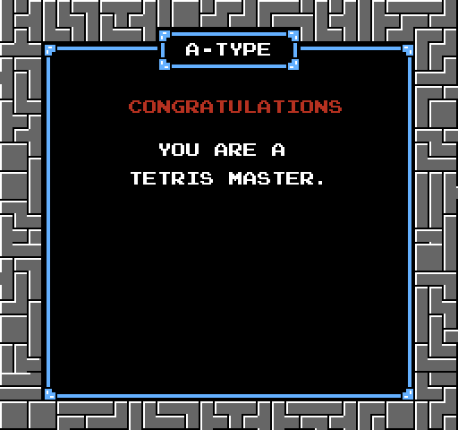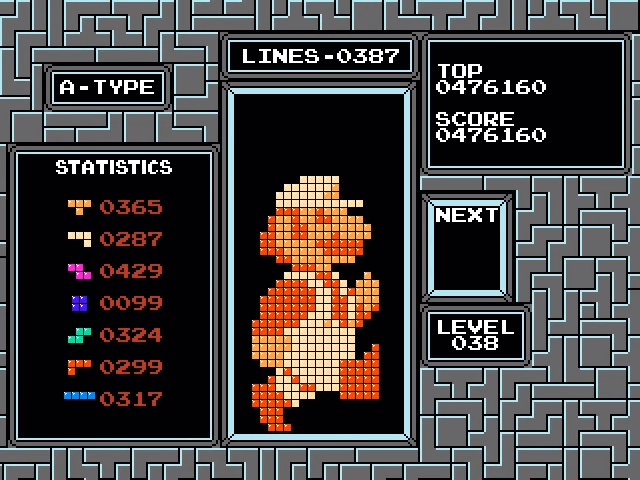
Turning, rearranging, and lowering a predetermined sequence of shapes, Tetris Printer Algorithm uses the Tetris mechanics to generate arbitrary bitmaps.
Algorithm description
The algorithm converts the pixels of the source image into the squares of the Tetris field line by line, moving from bottom to top. To generate a single square, the algorithm assembles a structure consisting of a rectangular area that is completely supported by one square below it. After the assembly of the rectangular region is completed, its lines are cleared, leaving one square under it. Here are three examples of this behavior.


As shown below, the algorithm can also generate several squares with one structure.

In the process of constructing a row, all the squares created in this way must be based on something. In the images shown above, the generated squares are on the floor of the playing field. However, if an arbitrary line contains holes, then it will not be able to provide the support necessary to build a line above it. The algorithm solves this problem by creating a flat platform on top of the hole line. In the animation below, a platform built on top of a line consists of one red square. A platform is a temporary structure, and inserting the last shape removes it.

The row of 5 red squares shown below is on top of the row of 3 red squares. This is realized by building a flat platform on top of the bottom line. The platform provides the support needed to generate 5 red squares. At the end, the platform is deleted by inserting the last shape, and the new line falls into place. Note that if the algorithm needs to generate rows in the reverse order (a row of 3 red squares above a row of 5 red squares), then the platform will not be needed.
One Square Patterns
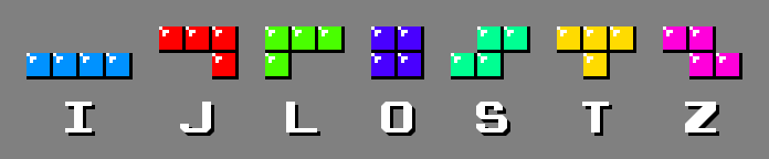
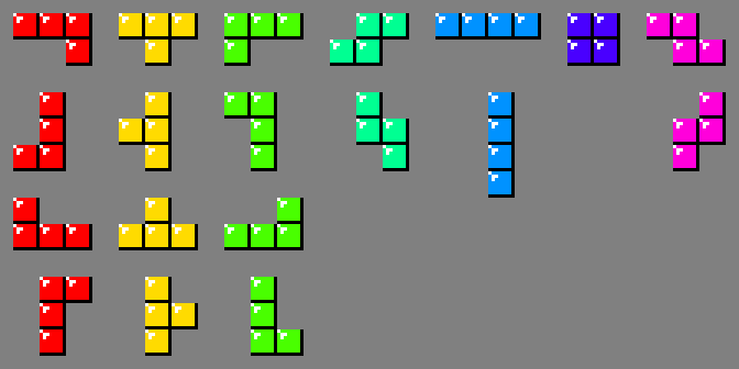
For reference, I will give the names of 7 tetramino (game pieces).
The version of Tetris Printer Algorithm presented in the article is designed specifically for rendering sprites from old video games. These games packed graphics in 8 × 8 tiles, and 2 bytes were allocated for each pixel. Therefore, sprites usually contained only 3 colors plus transparent areas and most often had a size of 16 × 16 or 16 × 32 pixels.
The animation below shows all the patterns used to create individual squares. Each pattern uses interchangeable tetramino J, T, and L, creating a single square at the bottom. The algorithm assigns this tetramino to one of the 3 colors present in the sprite. The rest of the tetramino is assigned arbitrary colors. Throughout the gameplay, all colors remain constant.
Due to the shape of the three tetramino, it is impossible to create a square from all three colors in the first two and last two columns. Therefore, the minimum width of the playing field for rendering a sprite with a width of 16 pixels is 2 + 16 + 2 = 20 squares. However, it turned out that 20 is too little.
As shown below, the area above the single bottom square cannot consist of only one line, because the only figures that can fit in it (tetramino I) have no support.

With two lines, the only way to stretch the whole playing field so that it has support is to use tetramino S and Z. But in this case, holes will remain in the top line.
The minimum number of lines required above the bottom square is 3, and as shown several times above, such patterns exist. 20 squares is the minimum width required to place a sprite with a width of 16 pixels. But 20 × 3 + 1 = 61, and this number is not divisible by 4, which means it cannot be built from tetramino. However, a width of 21 gives us 21 × 3 + 1 = 64, and it can be built from 16 tetramino. In fact, this width allows the algorithm to render sprites up to 17 pixels wide.
The playing field of the original Tetris has a size of 10 × 20 squares (1: 2 ratio). In this version of the algorithm, this ratio is preserved - the playing field has a size of 21 × 42 squares.
Since tetramino J, T, and L are interchangeable when creating one square, and 3 squares of these tetramino are involved in creating a line above it, there are 21 - 3 = 18 patterns for creating a single square. However, due to mirror symmetry, there are actually only 9. There are three lines of cleansing for most of these 9. However, a thorough computer study showed that the two patterns needed more. The next possible option is 7 lines, because 21 × 7 + 1 = 148, which requires 37 tetraminos. As shown in the images below, such patterns exist.
Multiple Square Patterns
Patterns for creating multiple squares are limited to the same three colors created by the patterns of a single square. The resulting squares are created from tetramino J, T and L, each of which occupies 3 squares in a line above the creation line. The maximum number of squares that can potentially be created with a single pattern is 21/3 = 7. However, for sprites with a width of 16 pixels, the rightmost tetramino cannot create a square. Even in the case of sprites with a width of 17 pixels, it can create a square of only one color. Therefore, the pattern of creating from 7 squares is rarely used.

The number of patterns for creating an arbitrary number of squares can be determined using the combinatorics of enumerations. Consider the pattern below, representing a row above a row of three squares. Each block of three adjacent white squares represents a part of tetramino; created squares are not shown.

Three tetramino create 4 voids. There are 21 - 3 × 3 = 12 dark squares that can be arbitrarily inserted into these voids to form a specific pattern. The number of ways to distribute these dark squares can be calculated by placing them on a line in which single white squares are treated as dividers.
So, the task was reduced to calculating the value of the polynomial coefficient. Looking at these white squares, you can understand that this is a question of the number of ways to choose 3 out of 15.
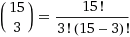 = 455.
In the general case, for n it is equal to
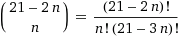 . But due to mirror symmetry, in fact, they are half as much; if the quantity is odd, then dividing by two, we round to the nearest integer to include in it a perfectly symmetric pattern that should exist in this set, as, for example, shown below for the case with 455.

Applying this formula to 7 tetraminos, we will confirm the obvious: there is only one pattern for creating 7 squares.
The pattern of creating 6 squares can be built in two ways: two filled lines (2 × 21 + 6 = 48) and six filled lines (6 × 21 + 6 = 132), which requires 12 and 33 tetraminos. The above formula shows that there are 84 patterns for creating 6 squares, but only 35 of them can be built from 2 full lines. 49 patterns require 6 lines. The numbers are odd due to the symmetrical patterns shown below.
It is also worth noting that 2 lines are possible here, because in contrast to the pattern of creating one square that required tetramino S and Z, 6 figures are used in these patterns.
The table below shows the number of squares created by each type of pattern, the number of complete lines, the number of tetramino used, and the number of patterns.
| Created Squares | Full lines | Tetramino | Patterns |
|---|---|---|---|
| one | 7 and 3 | 37 and 16 | 19 (4 and 15) |
| 2 | 6 | 32 | 136 |
| 3 | 5 | 27 | 455 |
| 4 | 4 | 22 | 715 |
| 5 | 3 | 17 | 462 |
| 6 | 2 and 6 | 12 and 33 | 84 (35 and 49) |
| 7 | one | 7 | one |
Examples of patterns.

Platforms
Before constructing a line, the algorithm examines the line below it. If the bottom row cannot provide support for all the squares above it, then a temporary platform is needed. When the platform is removed, a new line goes down, and due to how gravity is implemented in the original Tetris, some squares remain hanging in the air.
The illustration below shows 10 platform patterns. The construction of the platform begins by lowering the tetramino T over one of the squares of the last generated line. The remaining tetraminos rely on this first T. That is, if the previous generated line contains at least 1 square, such as the red square in the image below, we can create a flat platform above it to generate the next line.
In the middle of building the platform, the bottom line is completed and deleted, leaving three lines above it. The last J or L tetramino that will delete these lines is not inserted until the creation patterns generate the next sprite line on top of the platform. This last figure prevents the creation of squares in the first and last two lines. But, as mentioned above, due to the geometry of the tetramino J, T, and L used in this process, the patterns for creating squares are limited to 17 inner columns.
In addition, out of 19 possible ways to build platforms on top of Tetramino T, there are only 10 shown above.
Packed Matrices
As stated above, one subset of the 6 squares creation patterns involves clearing only two lines. All other patterns require 6 lines. To understand why this is the case, consider the pattern below.

These tetramino are interchangeable with tetramino J and L, and each of them adds 3 adjacent squares to the common row. The rows to be completed are represented by the matrix shown below.
Now it’s all about packing empty space with tetramino. Starting on the left, the only option is to use the tetramino I sequence.
The only way to fill the remaining space is to use J and O or I and L. Both options are shown below.
Unfortunately, tetramino O and L are not supported in the matrices shown above. This 6 squares pattern requires a larger matrix.
A similar problem arises in two patterns of creating one square. Consider the matrix below:
The only way to fill the bottom line on the right is by chaining the sequence Z.
Similarly, the only way to get 3 empty squares in the lower left is tetramino S.
In the middle line there is an empty square between S and Z and the only way to fill it is to use tetramino J, T or L, as shown in the figures below.
Inserting any of these shapes divides the blank space. The empty area on the left contains 5, 6, and 7 voids, respectively. Since none of these values is divisible by 4, it is impossible to continue. A larger matrix is required for this single square pattern.
The same applies to another pattern for creating one square, shown in the matrix below.
After using tetramino S and Z to fill most of the bottom line, there is an empty space between them in the middle line.
As shown in the images below, the hole insert divides the empty space, and the empty area on the left contains 9, 10, or 11 squares, respectively; none of the numbers are divisible by 4.
But packing matrices is not the only way to generate a squares pattern. For example, take a look at the 4 squares creator below.

The following is an attempt to render the pattern as a set of packaged tetraminos.
The last L is skipped because the space for it is formed only after the completion and removal of the third row.
But after a thorough search, it was discovered that this technique does not provide the aforementioned one-square patterns with the ability to work with only 3 lines. In addition, it does not allow it to implement any new 6-square patterns in two lines. There is no need to look for the remaining patterns outside the packed matrices, because they already use the smallest possible amount of tetramino. And limiting ourselves to packed matrices, we will find all the necessary patterns much faster.
Pattern Search
To simplify data output, Tetris Printer Algorithm is limited to creating tetramino at the top center point of the playing field, turning it, moving horizontally and lowering it. He never has to move the figure horizontally after passing some distance. This restriction greatly reduces the search space, because it does not allow the formation of gaps under the figures added to the matrix. For example, let's look at the following 3 squares matrix.
If we throw J in the center of the matrix, as shown above, then we get a gap of 2 empty squares, which cannot be filled with subsequent figures. Therefore, the search will not follow this path.
Since covered gaps are not allowed, each column in the matrix can be considered as a stack of filled squares and the height of these stacks fully describes the contents of the entire matrix. Regardless of the number of rows, a one-dimensional integer array with 21 elements will be sufficient to describe a two-dimensional matrix.
When a figure falls into the matrix, the heights of the stacks of the corresponding columns increase. To accelerate this process, all tetramines are analyzed in advance. There are 19 tetramino turns, and the search considers each of them to be a unique figure.
Tetramino J in the upper left corner of the image occupies 3 columns. When lowering onto a matrix of height, 3 adjacent stacks increase by 1, 1 and 2 squares, respectively. But before you can lower the figure, the lower profile of the figure must correspond to the upper profile of the respective stacks. If this J were lying on the floor of the playing field, under each of these columns there should have been gaps of 1, 1 and 0 empty squares. Since gaps are forbidden, the relative heights of 3 piles will have to fully match the pattern.
Another consequence of the lack of gaps was that when the figures fall into the matrix, the rows are filled from bottom to top. It is not possible to fill a row in the middle of a matrix before or simultaneously not completing all the rows below it. In the process of filling the matrix, its lower boundary actually moves up. Therefore, a matrix column stack can provide support only if its height minus the number of completed rows is greater than 0. When a shape is added to the matrix, at least one of the corresponding columns must provide support.
The search stores a second one-dimensional array containing the number of filled squares in each row. The above J contains in the corresponding lines 3 and 1 a square. When you insert it into the matrix, these values are added to the corresponding elements of the array. The number of completed lines is the number of elements with a value of 21.
As stated in the previous section, if the added figure divides the matrix, then the sizes of the resulting areas should be divided by 4. For example, in the image below, adding I creates 2 areas, each of which contains 46 empty squares. Since 46 is not divisible by 4, there is no longer any way to fill in the remainder of the matrix.
Separation appears when the height of the stack is equal to the height of the matrix. After inserting a figure by incrementing the heights of the respective stacks, the dimensions of all divided areas of empty space can be determined by scanning the array of heights and adding up the space remaining in each stack. This number is checked and reset when a split is detected.
The search used to generate all patterns uses randomized incremental construction, a backtracking algorithm that systematically checks all combinations in random order. Incremental construction of a solution by randomly inserting shapes makes it grow like a crystal. Randomness provides an irregularity containing broken faces that serve as the basis for subsequent added shapes. Most of the matrix is packaged randomly very quickly, and when empty space becomes scarce, backtracking comes into play.
Before performing the search, random permutations of 371 ways of adding a figure to the matrix are performed. The pseudo code of the search function is shown below.
private Result search(Matrix matrix, int remaining) { if (remaining == 0) { return SOLUTION } attempts := attempts + 1 if (attempts >= MAX_ATTEMPTS) { return TIMEOUT } if ( S Z) { S Z if ( ) { Result result := search(matrix, remaining - 1) if (result == SOLUTION) { return SOLUTION } if (result == TIMEOUT) { return TIMEOUT } } } for( , ) { if ( ) { Result result := search(matrix, remaining - 1) if (result == SOLUTION) { return SOLUTION } if (result == TIMEOUT) { return TIMEOUT } } } return NO_SOLUTION }
The original matrix passed to the search function is empty, with the exception of the bottom row containing blocks of 3 adjacent squares. It is transmitted along with the number of remaining figures that need to be added. If
remaining
is 0, then the matrix contains the solution and the function returns. Each recursive call increments the global number of attempts
attempts
. If it exceeds
MAX_ATTEMPTS
, which has a value of 1000, then the search starts again.
The third
if
tries to add tetramino S or Z to the bottom of the matrix if space allows it. The meaning of this is to avoid situations like the one shown below, when the algorithm spends time filling part of the matrix, not being able to fill the rest due to lack of support.
Thanks to the
if
it quickly forms a platform on which to build:

To attempt to add a figure to the matrix, the above checks are required. The algorithm checks if the figure will have support, given the completed lines. It also checks to see if it divides by 4 the size of each individual empty space created by the insertion of the shape.
Image conversion
Tetris Printer Algorithm converts each line of the bitmap into a series of passes. Moving from left to right, each passage in a "greedy" way inserts tetramino J, T and L to where they are placed. For example, the image below shows a row of 16 pixels of a bitmap.
The image below shows the 5 passes required to cover these 16 pixels.
The sequence of shapes that the algorithm is trying to insert is determined by the colors of the pixels. So that the shapes do not overlap, a one-dimensional array of Boolean values is used. To insert a figure, 3 zero elements must be present in the array. Upon successful insertion of figure 3, the corresponding array elements take the value 1.
To track completed pixels between multiple passes, a second one-dimensional array of Boolean values is used. When each item is 1, the line is complete.
At the end of each pass, the image converter searches the table for all patterns for creating one or more squares. To the output, it passes the corresponding pattern with the tetramino J, T and L inserted at the bottom. For example, the first pass shown above is displayed as the following pattern of creating 5 squares:
Real time search
The image converter described in the previous section is extremely fast because it uses a constant table containing all the patterns for creating squares, and does not search them in real time. However, real-time search can use patterns that are not in the table, and therefore, greatly reduce the amount of tetramino needed to generate the image. He uses the squares created in previous passages, using them as additional supports. For example, as mentioned above, the following pattern for creating one square requires 7 full lines.
But one red square created in the previous passage in the lower left corner of the image below provides additional support, reducing the number of filled lines to 3.
In addition, a real-time search can cover 3 adjacent pixels of the same color by flipping tetramino J, T or L.
In fact, it can combine inverted and inverted tetramino, covering a large number of pixels in one pass. For example, the above 5 passes needed to cover 16 pixels can be reduced to the one pass shown below.
To obtain this pattern, the image converter begins by eagerly packing upturned tetramino J, T, and L.
Then he eagerly tries to add the unturned versions, and in this case he manages to add another J.
In principle, a pre-computed lookup table can also be used in this process, but the sheer size of such a table makes it inapplicable in practice.
In this example, 8 squares in a row above the row to be created are added to the bottom row of the empty matrix. For n squares on a 21-square-wide playing field, the height of the matrix h is the smallest positive integer such that 21h - n is divisible by 4. In this case, a matrix of height 4 is required.
Real-time search works in exactly the same way as the search algorithm described above, but has minor improvements. As before, the matrix column stack provides support only if the column height minus the number of completed rows is greater than zero. When the difference is zero, the column stack should not provide support. However, in this version, if it is equal to zero, it checks the squares in the created line generated by previous passes. That is, any squares in the row below the bottom row of the matrix provide support for empty columns.
In addition, since the search is performed in real time, it will be impractical to make it exhaustive. If he did not find a solution after a given number of attempts, then he adds 4 more rows at the top of the matrix, and then tries again. After that, if he still could not find a solution after a given number of attempts, then in the current passage he returns to the methodology with pre-computed search tables and image conversion described in the previous section of the article.
For printing, you must follow the instructions displayed by the image converter on the Tetris playing field. The printer creates a specific tetramino at the top center point of the playing field in a standard orientation. Then the printer rotates it, shifts it horizontally and lowers it. This process is shown in the video:
Source
The source code for the Java 7 project is available here .
Search algorithms for pre-prepared tables and real-time are in the packages
search.precomputed
and
search.realtime
. They use some common classes located in the
search
package. The results of a pre-calculated search are stored in the
patterns
package as a sequence of text files. Text files store packed matrices as ASCII characters, starting with
A
For example, the first 3 matrices in
emitters1.txt
(the set of patterns for creating one square) look like this:
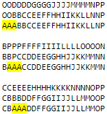
As repeatedly stated in the article, 3 adjacent characters
A
in the above matrices can be replaced with tetramino J, T or L. Characters
B
,
C
,
D
and so on represent the sequence of tetramino that you need to create.
The
imageconverter.ImageConverter
class contains the
main
method, which receives a single command line argument: the name of the image sprite file. An image cannot be larger than 17 × 32 pixels and cannot contain more than 3 opaque colors. All other pixels must be transparent.
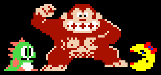
Interestingly, in old video games, developers often used the background to get extra color. For example, pupils and mouth of Bubble from Bubble bobble, pupils of Donkey Kong from Donkey Kong and eyebrow with a mole of Miss Packman from Ms. Pac-Man is actually transparent. Black is obtained from a solid background.
The background of the Tetris playing field can be used in a similar way.
ImageConverter
output looks like this snippet:
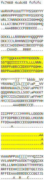
The 3 hex values in the first line are 3 opaque colors extracted from the sprite image file. They correspond to the colors of tetramino J, T and L. The colors of other tetramino do not affect the image. The remaining blocks are packaged patterns executed on the playing field (characters after
Z
and up to
a
see in the table of ASCII characters ). The blocks highlighted in yellow make up the platform. The first block adds the platform, the second removes it.
The
printer.Printer
class receives a text file in this format and generates an image file by playing Tetris.
The printer algorithm used to generate a video resembling the NES version of Tetris defines each type of tetramino in each block of a text file. Then it moves in the opposite order from the starting point and the initial orientation to the rotation angle and the coordinates of the lowering of the figure indicated in the file. Note: due to the extremely high speed of falling figures, it is impossible to go beyond level 30 in the real NES version of Tetris. It is assumed that the printer transmits all its commands to the playing field quickly enough. to compensate for this.
To regenerate pattern files, use
search.precomputed.PatternSearcher
. It can be customized by changing the constants at the beginning of the source code file.
public static final int MATRIX_WIDTH = 21; public static final int MATRIX_HEIGHT = 4; public static final int EMITTED_SQUARES = 4; public static final int RANDOM_SETS = 100000; public static final int MAX_ATTEMPTS = 1000;
RANDOM_SETS
is the number of random permutations of 371 ways to add a figure to the matrix. When set to
100000
, it takes several seconds to initialize permutations at startup. In addition, their storage requires more than a gigabyte of memory.
MAX_ATTEMPTS
controls the execution time of the search. A relatively small value of
1000
allows the search to quickly discard random beginnings that fail to show themselves well. However, in order to prove that for a specific matrix size and the number of created squares there is no solution, it is necessary to fully explore the entire search space. To do this, you can set
MAX_ATTEMPTS
to
Integer.MAX_VALUE
.
Similar constants are found in
search.realtime.RealtimeSearcher
, which is used by the image converter. As mentioned above, a large
RANDOM_SETS
value requires an increase in maximum memory and leads to a longer run.
MAX_RETRIES
controls the number of attempts, after which the real-time search surrenders and returns to the search with a pre-computed table.
Keep in mind that both search algorithms use 100% of the CPU, creating many parallel threads that are equal in size to the number of processors available.