In general, the data loading mechanism in the ECU (electronic control unit) is described in the UDS diagnostic protocol, namely the functions:
34 - Request Download
36 - Transfer Data
But in terms of implementing UDS, automakers are not squeamish to make changes / additions to the protocol, creating a proprietary add-on. In my case, the update process looks something like this:
- Logging into an extended diagnostic session
- Reboot in bootloader
- Obtaining security access to allow a data load operation
- Transfer of the address in memory where the record and data volume will be kept
- Data loading
- Doing what was loaded
- Next is programming the EEPROM with the program that you downloaded before.
Points 1-3 were not difficult, but what to do next? Where to get the address and the maximum amount of data? How after boot to do what was downloaded? Actually, for the sake of this, an article is being written.
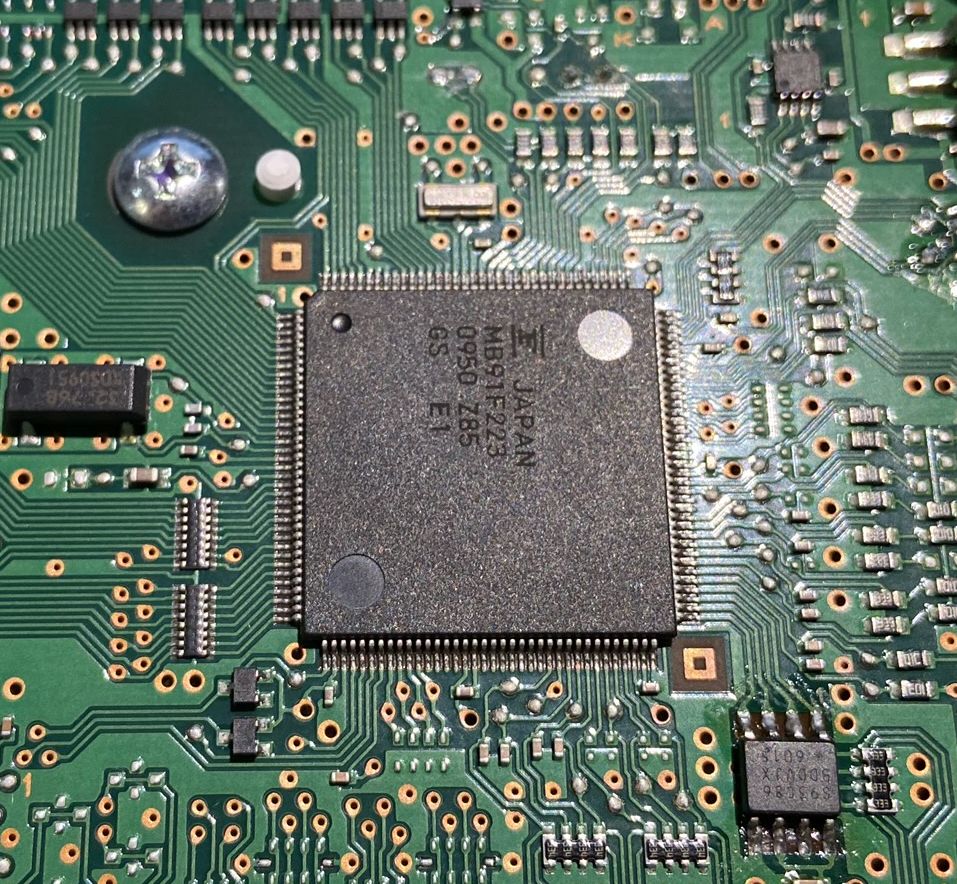
A combination of devices was chosen as a test subject, because, firstly, I have one more in case of an apocalypse, and secondly, its controller can be read with a simple USB-RS232 adapter. Having studied the insides, we have a Fujitsu MB91F223 controller. This is a 32-bit micron with a FR60Lite core, 512 KB of memory and 16 KB of RAM. Datasheet, RM, Assembler manual, a programmer for it are easily searched on the Internet, I will not stop here. Here he is handsome:
Action plan:
- Find Diagnostic Request Handlers
- Find addresses in memory where you can write something
- Find a way to execute recorded code
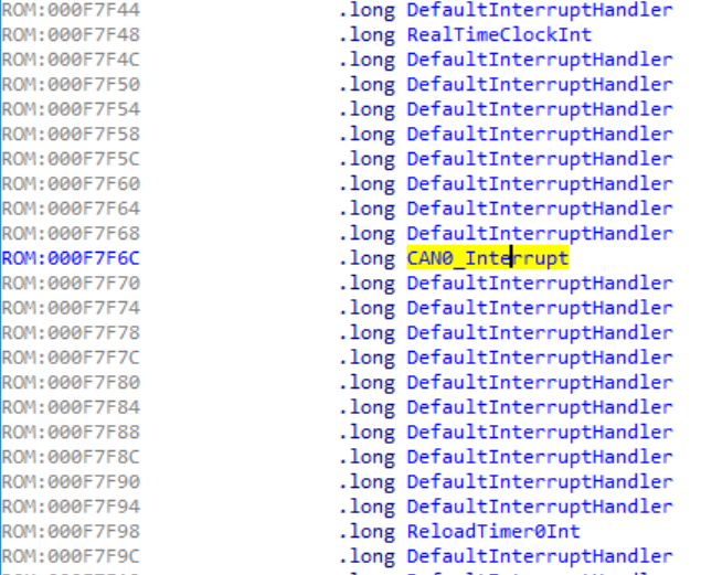
To perform step 1, you need to study the interrupt handler from the CAN bus and understand where the data is stored for further processing. Many controllers have a so-called interrupt vector table, which contains the addresses of the functions responsible for processing them. In the Fujitsu FR family, this table is in its industry, and the pointer to it is stored in the TBR register (Table base register). A simple text search in the IDA gives a positive result and the address of the interrupt table with us.

According to the manual, the CAN interrupt address is at offset 0x370 from the beginning of the TBR. Here he is.
He, but already at full height, is also a message handler using the ISO-TP protocol 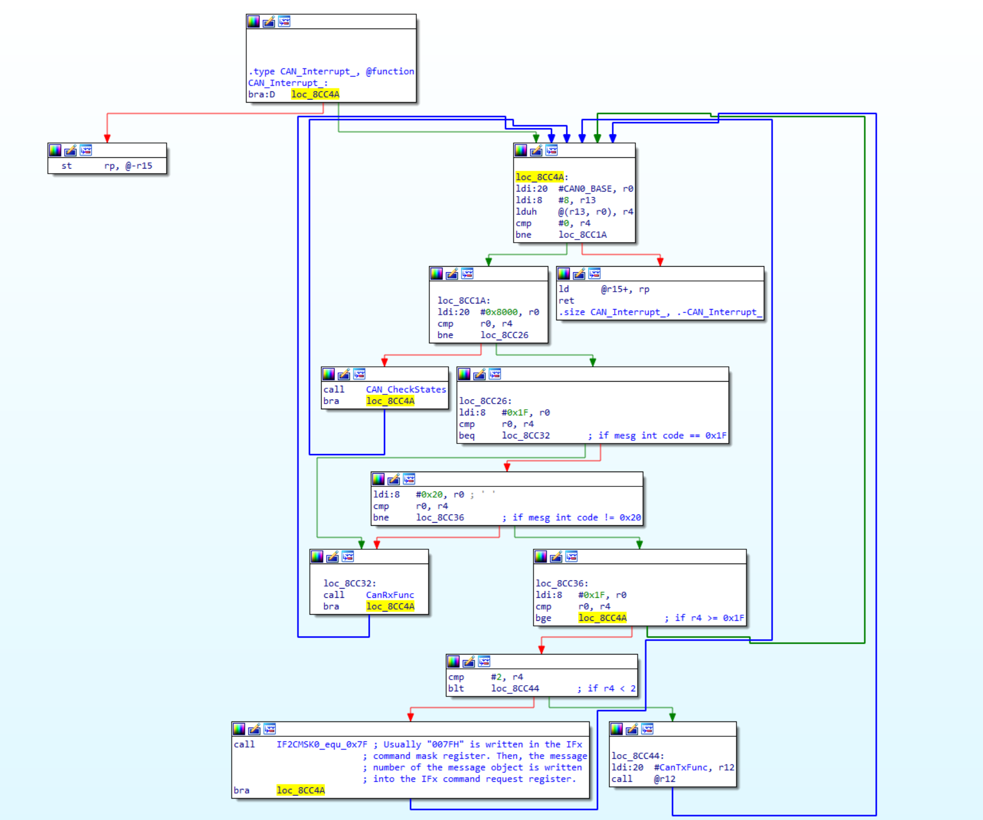
The ISO-TP handler is not complete, but where frames of different types diverge
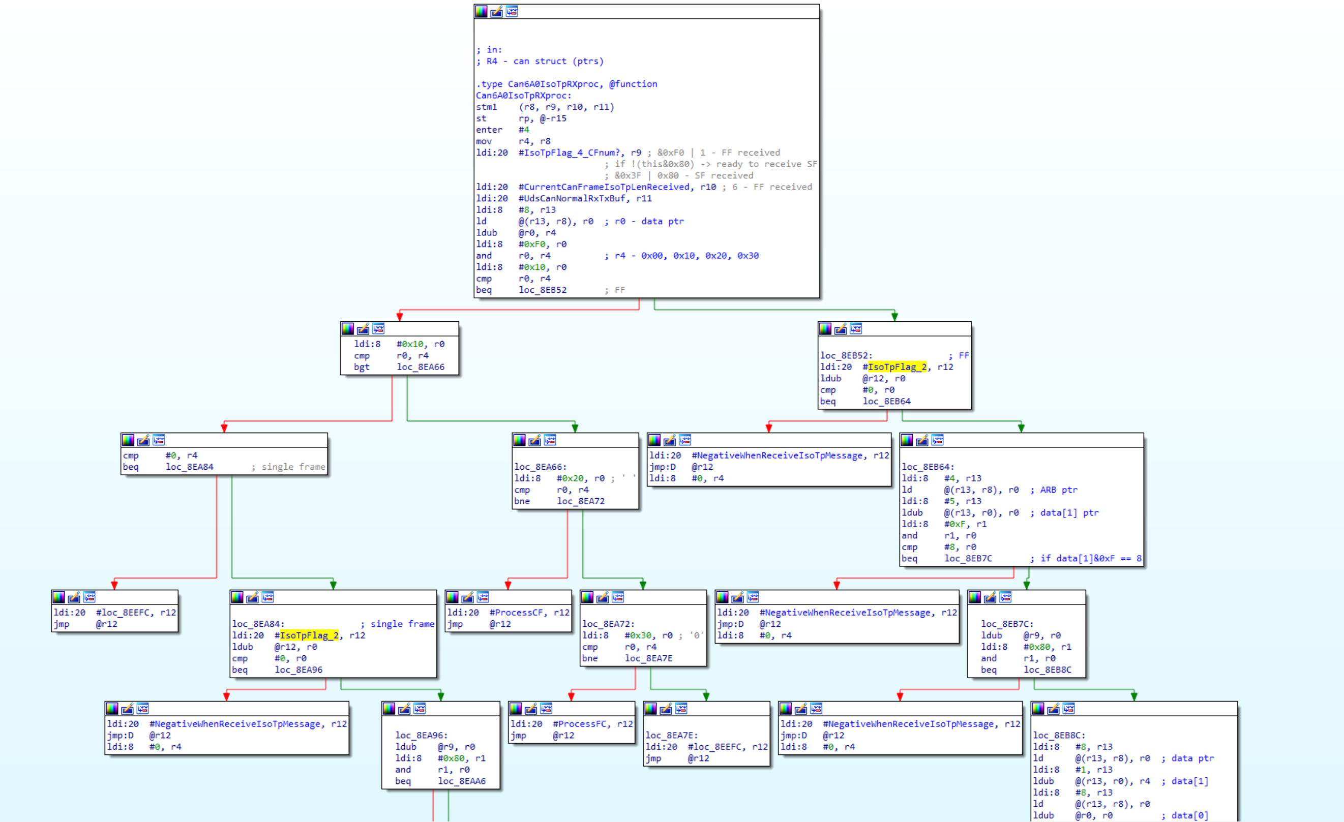
The ISO-TP handler is not complete, but where frames of different types diverge
From the dealer diagnostic software database, I had the SID and LID (31E1) identifiers of the UDS protocol that started the code execution procedure, this simplified the task and allowed me to act from the end to the beginning. In the function handler 31E1, a fragment was found where the address belonging to the RAM area is loaded, and then a call is made to this address. Isn't this what we're looking for?

The search for using the constant 0x3F100 leads us to another place in the firmware, in the UDS 34 function handler - Request download! This is exactly what you need, the address for writing data and the maximum amount (0x700 bytes) in RAM is found.

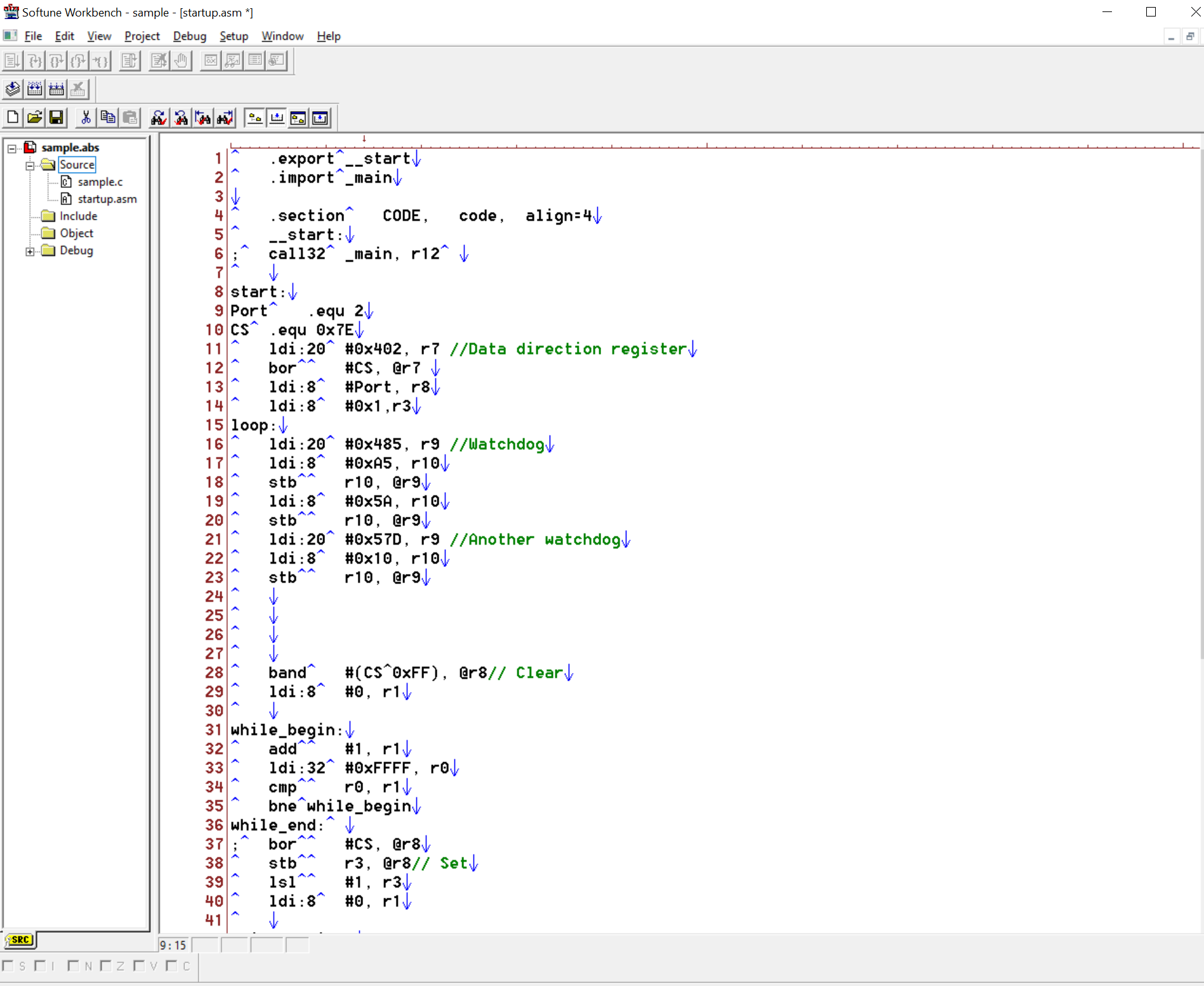
Now, after sending a command to request permission to download data 34 03F100 00 00010C (the address is indicated in italics in bold), the dashboard responds with a good 740401 in response. Next, user data is loaded using the Transfer data function and a command is issued to fulfill. We figured out the loading and execution, but now you need to find what to download. I did not find open source development environment for this microcontroller, but after a month there was a knock on cypress tech support (yes, not fujitsu, they either absorbed them, in general, I don’t know) they gave a link to an IDE called Shaggy Softune Workbench 97 years with which the compiler came under the FR kernel.
That's what it looks like, not a vscode pair.
In the screenshot, a fragment of the program for flashing LEDs (do not kick for the style of writing in assembler, this is my first experience).
The same code, but already in si
void delay(int loops) { while(--loops) { #pragma asm NOP NOP #pragma endasm __asm(" nop"); } } #define DDR2 (*((char*)0x402)) #define PDR2 (*((char*)0x2)) #define WPR (*((char*)0x485)) #define LVRC (*((char*)0x57D)) void wdt_reset(void) { WPR = 0xA5; WPR = 0x5A; LVRC = 0x10; } void main(void) { int current_pin = 2; DDR2 |= 0x7E; while(1) { wdt_reset(); PDR2 |= current_pin; delay(0x7FFF); PDR2 &= ~current_pin; delay(0x7FFF); current_pin <<= 1; if(current_pin >= 0x80) { current_pin = 2; } } }
Well, the result itself
With other nodes, everything looks pretty much the same, with the exception of the controller architecture and the order in which commands are executed. Is it safe to leave such loopholes in automotive equipment? Apparently yes, since the manufacturer does so. Why am I doing this? It was just interesting, well, the assembler was of interest to me for a long time, I met it, so to speak.
Subject - Mitsubishi 8100B197 instrument panel, communication on the CAN bus was carried out by the Tactrix OpenPort 2.0 adapter, software on a computer of its own design.