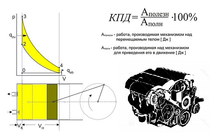
How important is it to have perfect code in the program for its fast and high-quality work? It is equally important for ICE to spend less energy where these costs can be avoided.Due to simplifications, the previous article raised questions of a critical nature among some of the habr-people. In this I’ll try to answer them in more detail as I promised, and also to reveal one of the basic principles of ICE of the last decades mentioned in the article “The evolution of the development of automobile engines from the beginning of the 90s.”
Units with flexible response characteristics in ICE
The first, and probably the most famous example of increasing the flexibility of characteristics in ICEs was hydraulic expansion joints, which ensured the rejection of the thermal gap and smoother valve operation.
Self-regulation and smooth operation of hydraulics was also used in other components and units of the internal combustion engine.
For example , chain tensioners provided the same advantages as pushers, but the Fiat MultiAir system can be considered the most striking example of the triumph of hydraulics.
The engine, as well as the machine where this system is installed, are unique in themselves, so we will dwell only on certain points.
So from the video it can be seen that so far only the inlet valve is opened hydraulically, but then I will show that the release valve also has an effect in another system related to the complete control of the valve closing process. Therefore, in fact, hydraulics today is already able to control almost all processes in the cylinder head. Amazingly, with all the complexity of the system, its operation is an excuse, an example of the prospects for the next stage - electro valves.
There is a truth and a compromise option from koenigseggThe next example - an adjustable oil pump can already be considered a long-awaited completion rather than a technical breakthrough.
As you can see, the complexity of the work here is justified by the optimized range of work.
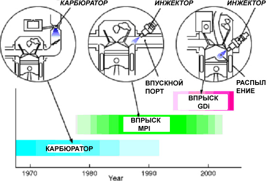
The next “hydraulic” example is the injection system, where truly revolutionary changes took place.
Perhaps we start with the fact that the transition from mono-injection to distributed, and then to direct in gasoline engines affected a number of characteristics.
Such as injection pressure, injection cycle time and the price of this equipment (the latter is probably the most obvious point).
Injection pressure - with different engine operating modes, it can be from 3 to 11 MPa.
The injection cycle time can vary (and sometimes the injection can take place in one working cycle up to several times).
Direct injection can provide six fuel mixing options.
- layered distribution of the mixture;
- homogeneous mixture;
- homogeneous lean mixture;
- homogeneous layer-by-layer distribution of the mixture;
- double injection to protect the engine from detonation;
- double injection to heat the converter.
The price of the last type of injection is considered the highest for gasoline ICEs (therefore, it is not by chance that combined injection systems appear).
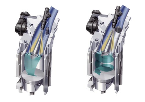
One of the possible options for reducing the cost of direct injection are Orbital injectors.
The principle of operation here is this - the air to the air jets comes in compressed form from a special compressor at a pressure of 0.65 MPa. The fuel pressure is 0.8 MPa. First, the fuel nozzle is triggered, and then at the right time the air jet, so the fuel-air mixture in the form of an aerosol is injected into the cylinder with a powerful torch.
The nozzle installed in the cylinder head next to the spark plug injects a fuel-air jet directly onto the electrodes of the spark plug, which ensures its good ignition.
Ford Sci (Smart Charge injection), Mitsubishi GDI (Gasoline Direct Injection), VW FSI (Fuel Stratified Injection), HPi (High Pressure Injection), Mercedes CGI, Renault IDE, SCC (Saab Combustion Control. A distinctive feature of the system is the integration of candles ignition and injector into a single module (SPI). Using compressed air, fuel flows directly into the cylinder block and immediately ignites.) - all these systems are different direct injection options.For diesel engines, differences in fuel equipment have become less significant, since they were originally direct injection. Here, an increase in injection pressure was a contributing factor, and improved process control was more affected. The mechanical nozzles of a diesel engine are now almost everywhere replaced by electromechanical ones. "Diesels" as well as gasoline engines with direct injection also have a "multi-pulse mode" (injection per cycle from 1 to 7 times).
The main confrontation in diesel injection technology is between the individual pump nozzles and the Common Rail system.
Another significant change in the injection system was an increase in the number and quality of sensors used to correct injection. The engine management system < currently has more data for processing and correction directly, and not in different workarounds, as it was before.
In the early stages of the development of electronic engine control systems, the process of manually setting the injection through the ECM was reminiscent of working with Big Data. And there, and there, in principle, you don’t know exactly the final result at the beginning of the process, but still you hope to find the “gold mine”. When manually setting the injection, one had to rely only on experience and intuition to get the desired result.
In the ignition system, conversions also went in the direction of increasing power and accuracy.
Contact ignition with one coil replaced non-contact (with one, and then with two coils), and the development of individual ignition coils on each cylinder.
a small reference to the previous article - there are also two ignition coils for the entire engine, which, due to the peculiarities of operation, give a spark twice a cycle (moreover, one spark passes in the cylinder not in the ignition cycle).Electric generation also became more economical, so one of the results of the development was a disconnectable generator.
The principle of operation here is the following - when the car slows down, the generator turns on at maximum operating mode. During subsequent acceleration ... it is switched off to certain limits, which depend on a number of parameters. This mode of operation allows you to distribute the load better, since when the engine brakes, the generator provides additional resistance, and when accelerating, on the contrary, it removes the load from the internal combustion engine.
Alternator with INA clutch. Air conditioning using the same with a disconnectable clutch has become more economical. Now he does not load the shaft with “idle” compressor operation.The turbine as an element, initially little susceptible to complication, nevertheless became "more flexible."
But the exhaust gases do not always exit into the “pipe”, sometimes some of them “return” back to the combustion chamber.
The operation of this system allows you to adjust the temperature in the combustion chamber due to exhaust gas recirculation (there are systems with exhaust gas cooling , and without, during recirculation).
The last “impossible” transformation at the moment can be considered the Homogeneous Charge Compression Ignition (HCCI) cycle.
The meaning of this technology is to combine 2 types of fuel combustion in one engine. When applying this cycle, it becomes possible to burn a mixture of gasoline both with a candle and with a "diesel" (using compression).
Units that have lost mechanical connection with ICE
The fuel pump is the first to fall under this definition.
In most modern injection cars, this unit, as a rule, is located in a gas tank, has slight differences in design ... and is completely devoid of any mechanical connection with the internal combustion engine. The truth is now, even as a tuning, they have learned to put an electric gasoline pump even on carburetor cars.
The efficiency of its work has increased, especially after they began to install systems without a "return" (supply of fuel through the return channel to the gas tank).
The next purely electrically “connected” element is the throttle, which traditionally has always been connected to the gas pedal, but now it is an “independent” element from the pedal.
The fact is that from the point of view of the operation of various interconnected systems in the engine, it is not always necessary to directly affect the damper and direct communication is more likely an obstacle than help. Therefore, for many reasons, the separation of the gas pedal (Potentiometer) and the electric damper is quite justified. A certain role in the introduction of the electric throttle also played the norms of toxicity of the exhaust.
The next system that lost its “connection” was the cooling system.
I think everyone knows about the electric cooling fan (although earlier in the 90s there was still such a thing as a drive through a viscous coupling of a cooling fan).
Replacing the viscous coupling with an electric fan is still relevant.
But about the presence of 2 cooling circuits separately for the cylinder head and cylinder block?
All this is “seasoned” with the fact that the thermostats are more “nimble” here, that is, they have also lost a direct physical relationship due to the introduction of an electrical component (therefore, the speed here depends not so much on the effect of temperature on the expanding working element, but on the operation of the heating element inside )

The separation of the circuits on the cylinder head and the cylinder block made it possible to maintain different temperatures of the coolant in them. In contrast to the standard, in the dual-circuit cooling system, the temperature in the cylinder head is ensured in the limit of 87 ° C, in the cylinder block - 105 ° C.
Since a lower temperature must be maintained in the cylinder head circuit, a larger volume of coolant circulates in it (about 2/3 of the total volume). The remaining coolant circulates in the cylinder block circuit.
When the engine starts, both thermostats are closed. Fast engine warming up is provided. The coolant circulates in a small circle of the cylinder head: from the pump through the cylinder head, the heat exchanger of the heater, the oil cooler and further into the expansion tank. This cycle is carried out until the coolant reaches a temperature of 87 ° C.
At a temperature of 87 ° C, the thermostat for the cylinder head circuit opens and the coolant begins to circulate in a large circle: from the pump through the cylinder head, heater heat exchanger, oil cooler, open thermostat, radiator and then through the expansion tank. This cycle is carried out until the coolant in the cylinder block reaches a temperature of 105 ° C.
At a temperature of 105 ° C, the thermostat of the cylinder block circuit opens and fluid begins to circulate in it. In this case, the temperature at 87 ° C is always maintained in the cylinder head circuit.
The last worthy of mention is the BMW electric pump. The decision to “electrify” a water pump is risky, since it requires not a small amount of energy, and this is probably why it has not yet been encountered by most other automakers. An electric pump is used on N52 engines: E60, E61, E63, E64, E65, E66, E87, E90, E91.
In addition to the directly attached equipment associated with the operation of the internal combustion engine, the hydraulic booster lost mechanical connection ... becoming in some cases an electric hydraulic booster , and at a maximum - an electric booster .
"Flexible" depending on the speed ...
In a previous article there was a question - “can a 4-valve ICE work without a part of the valves, or even without them?”
The answer is simple - not only it can, but it works (though there are nuances).
Opel's Twinport technology allows you to manage 3 in partial load mode.
The reason for this partial operation lies in the decrease in the filling of the cylinder with air when the throttle is partially open with a small load on the engine. This problem is partially solved by exhaust gas recirculation (EGR), but German engineers felt that this was not enough. To increase the speed of the air flow, they decided to "plug" one inlet valve with a shutter (in the photo on the right), which allowed them to swirl the air flow and increase its speed.
As a result, the use of Twinport saves 6% of fuel on a 1.6 liter engine. In general, together with EGR, savings can reach up to 10%.
A similar system is used by Opel on engines with direct fuel injection.
On Renault saffron, an air injection nozzle in the combustion chamber was used to create a turbulence in the cylinder.The following system is more radical in its approach to valve deactivation.Air injection improves the combustion process at low speeds, optimizing fuel combustion, which provides fuel savings of 8 to 14%.
Interestingly, the fact that air injection was later used in the exhaust tract to improve the ecology of the cold engine exhaust , and in the Koenigsegg Jesko supercar, compressed air is also injected into the exhaust duct to ... spin the turbine to eliminate the turbolag.
The principle is similar to big.LITTLE .
In one engine, when the valves are completely turned off in several cylinders, it becomes possible to obtain a smaller working volume to save fuel.
Volkswagen cylinder deactivation technology
The Audi A1 Sportback 1.4 TSI with a 4-cylinder engine is capable of “turning” at a speed of 1,400 to 4,000 rpm (partial load) into a two-cylinder using the cylinder shut-off system!Honda Variable Cylinder Management
There was a domestic analogue of such a system.
Professor P.I. Andrusenko in 1967 proposed an easier way to adjust the power of the internal combustion engine - turning off individual work cycles. In 1996, together with AvtoVAZ, this method was advertised at an exhibition in Detroit.
The principle of the professor’s idea is simple, you just need to turn off the fuel supply to different cylinders, which will ensure that you receive the required amount of energy at the moment. This is accomplished with the help of injection control, and the throttle valve remains completely open in the entire range of changes in motor loads! (I remind you that the BMW Valvetronic system also has a throttle valve that is completely open to increase the indicator KPD, but there it is “insurance” in case of system failure).
Advantages of the system:
- In the partial load mode, 20–23% with a decrease in toxicity by 2.5–4 times.
- Idle fuel consumption is halved.
Differences from those used now.
- The number of disconnected cycles can be any. The operation of the internal combustion engine in this mode can be optimized in terms of fuel composition over a wide range of revolutions and loads.
- When power is controlled by turning off the cylinders, their temperature regime changes, since they remain unused for a long time. With the DRC method, missed cycles fall on different cylinders, so they practically do not have time to cool.
- No major structural changes to the ICE are required.
Phase shift.
The next valve manipulation technology is phase shifters. The technology of phase shift has successfully improved the idea of 4 valves, and the design is so simple that they got to the AvtoVAZ engines.
The essence of the process is to change the opening time of the valves in the cylinder depending on the increase in engine speed. The reason here is simple - the combustion of fuel at higher speeds does not occur so quickly, which means that it takes time to “purge-open” the valves earlier. This is achieved by a small shift of the camshaft using a hydraulic clutch.
VVT-i
BMW Vanos
The “grandfather” of the phase shift is considered to be a split gear.Regulation of height of rise of the valve.
Basically, a split gear is used in tuning and ... with the imperfection of some motors, as it allows you to set the "correct" phases of opening and closing valves.
In addition to the shift, another “flexible” technology is used - “valve lift”.
MITSUBISHI MIVEC
Honda VTEC
BMW Valvetronic
Variocam porsche
The latest achievement of ICE at the moment is a variable characteristic of the compression ratio.
Examples of a similar system from the Swedes
and the German counterpart ...
As a result of development, these systems have not found application, but Nissan decided to rectify the situation, and presented its serial version of the system.
Despite the complexity of this engine, he is far from the main leader in "flexibility" - the Toyota Prius hybrid drive.
The combination of the joint work of the engine according to the Atkinson (Miller) cycle with an electric motor gives fuel consumption unattainable for conventional ICEs, the ecology of the exhaust, and efficiency.
Thus, the development of internal combustion engines came to the logical result of electrification, and even the processes started inverse to the whole tendency of the development of engines up to this point.
PS The period from the beginning of the 80s to our time can be safely called the time of cutting off unnecessary costs in the internal combustion engine. About the parallel process - miniaturization of ICE (downsizing) will be in the next article.
PPS If you have examples of analogies from the it sphere for the listed ICE technologies, you can write in the comments below (I’ll add the best to the article).