Introduction
The goal of this project is to create a clone of the DOOM engine using resources released with Ultimate DOOM ( version from Steam ).
It will be presented in the form of a tutorial - I do not want to achieve maximum performance in the code, but just create a working version, and later I will begin to improve and optimize it.
I have no experience in creating games or game engines, and little experience in writing articles, so you can suggest your own changes or even completely rewrite the code.
Here is a list of resources and links.
Book Game Engine Black Book: DOOM Fabien Sanglar . One of the best books on DOOM internals.
Doom wiki
DOOM source code
Source Code Chocolate Doom
Requirements
- Visual Studio: any IDE will do; I will work in Visual Studio 2017.
- SDL2: libraries.
- DOOM: A copy of the Steam version of Ultimate DOOM, we only need a WAD file from it.
Optional
- Slade3: a good tool to test our work.
Thoughts
I don’t know, I can complete this project, but I will do my best for this.
Windows will be my target platform, but since I use SDL, it will just make the engine work under any other platform.
In the meantime, install Visual Studio!
The project was renamed from Handmade DOOM to Do It Yourself Doom with SLD (DIY Doom) so that it would not be confused with other projects called “Handmade”. There are several screenshots in the tutorial where it is still called Handmade DOOM.
WAD Files
Before embarking on coding, let's set goals and think about what we want to achieve.
First, let's check if we can read DOOM resource files. All DOOM resources are in the WAD file.
What is a WAD file?
"Where is All my Data"? ("Where is all my data?") They are in WAD! WAD is an archive of all DOOM resources (and DOOM-based games) located in a single file.
Doom developers came up with this format to simplify the creation of game modifications.
WAD File Anatomy
A WAD file consists of three main parts: a header, lumps, and directories.
- Header - contains basic information about the WAD file and directory offset.
- Lumps - here are stored game resources, data of maps, sprites, music, etc.
- Directories - The organizational structure for finding data in the lump section.
<---- 32 bits ----> /------------------\ ---> 0x00 | ASCII WAD Type | 0X03 | |------------------| Header -| 0x04 | # of directories | 0x07 | |------------------| ---> 0x08 | directory offset | 0x0B -- ---> |------------------| <-- | | 0x0C | Lump Data | | | | |------------------| | | Lumps - | | . | | | | | . | | | | | . | | | ---> | . | | | ---> |------------------| <--|--- | | Lump offset | | | |------------------| | Directory -| | directory offset | --- List | |------------------| | | Lump Name | | |------------------| | | . | | | . | | | . | ---> \------------------/
Header format
| Field size | Data type | Content |
|---|---|---|
| 0x00-0x03 | 4 ASCII characters | ASCII string (with the values "IWAD" or "PWAD"). |
| 0x04-0x07 | unsigned int | Directory item number. |
| 0x08-0x0b | unsigned int | Directory offset value in the WAD file. |
Directory Format
| Field size | Data type | Content |
|---|---|---|
| 0x00-0x03 | unsigned int | The offset value at the beginning of the lump data in the WAD file. |
| 0x04-0x07 | unsigned int | The size of the "piece" (lump) in bytes. |
| 0x08-0x0f | 8 ASCII characters | ASCII containing the name "piece". |
Goals
- Create a project.
- Open the WAD file.
- Read the headline.
- Read all the directories and display them.
Architecture
Let's not complicate anything yet. Create a class that simply opens and loads WAD, and call it WADLoader. Then we write a class that is responsible for reading data depending on their format, and call it WADReader. We also need a simple
main
function that calls these classes.
Note: this architecture may not be optimal, and if necessary we will change it.
Getting to the code
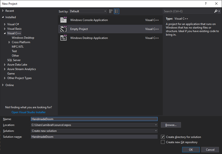
Let's start by creating an empty C ++ project. In Visual Studio, click on File-> New -> Project. Let's call it DIYDoom.
Let's add two new classes: WADLoader and WADReader. Let's start with the implementation of WADLoader.
class WADLoader { public: WADLoader(std::string sWADFilePath); // We always want to make sure a WAD file is passed bool LoadWAD(); // Will call other helper functions to open and load the WAD file ~WADLoader(); // Clean up! protected: bool OpenAndLoad(); // Open the file and load it to memory bool ReadDirectories(); // A function what will iterate though the directory section std::string m_sWADFilePath; // Sore the file name passed to the constructor std::ifstream m_WADFile; // The file stream that will pint to the WAD file. uint8_t *m_WADData; // let's load the file and keep it in memory! It is just a few MBs! std::vector<Directory> m_WADDirectories; //let's store all the directories in this vector. };
Implementing the constructor will be simple: initialize the data pointer and store a copy of the transferred path to the WAD file.
WADLoader::WADLoader(string sWADFilePath) : m_WADData(NULL), m_sWADFilePath(sWADFilePath) { }
Now let's get down to the implementation of the auxiliary function of loading
OpenAndLoad
: we just try to open the file as binary and, in case of failure, display an error.
m_WADFile.open(m_sWADFilePath, ifstream::binary); if (!m_WADFile.is_open()) { cout << "Error: Failed to open WAD file" << m_sWADFilePath << endl; return false; }
If everything goes well, and we can find and open the file, then we need to know the file size in order to allocate memory for copying the file to it.
m_WADFile.seekg(0, m_WADFile.end); size_t length = m_WADFile.tellg();
Now we know how much space a full WAD takes, and we will allocate the necessary amount of memory.
m_WADData = new uint8_t[length];
Copy the contents of the file to this memory.
// remember to know the file size we had to move the file pointer all the way to the end! We need to move it back to the beginning. m_WADFile.seekg(ifstream::beg); m_WADFile.read((char *)m_WADData, length); // read the file and place it in m_WADData m_WADFile.close();
You may have noticed that I used the
m_WADData
type as the data type for
unint8_t
. This means that I need an exact array of 1 byte (1 byte * length). Using unint8_t ensures that the size is equal to a byte (8 bits, which can be understood from the type name). If we wanted to allocate 2 bytes (16 bits), we would use unint16_t, which we will talk about later. By using these types of code, the code becomes platform independent. I will explain: if we use "int", then the exact size of int in memory will depend on the system. If we compile “int” in a 32-bit configuration, we get a memory size of 4 bytes (32 bits), and when compiling the same code in a 64-bit configuration, we get a memory size of 8 bytes (64 bits)! Worse, compiling the code on a 16-bit platform (you are probably a DOS fan) will give us 2 bytes (16 bits)!
Let's check the code briefly and make sure everything works. But first, we need to implement LoadWAD. While LoadWAD will call "OpenAndLoad"
bool WADLoader::LoadWAD() { if (!OpenAndLoad()) { return false; } return true; }
And let's add to the main function code that creates an instance of the class and tries to load WAD
int main() { WADLoader wadloader("D:\\SDKs\\Assets\\Doom\\DOOM.WAD"); wadloader.LoadWAD(); return 0; }
You will need to enter the correct path to your WAD file. Let's run it!
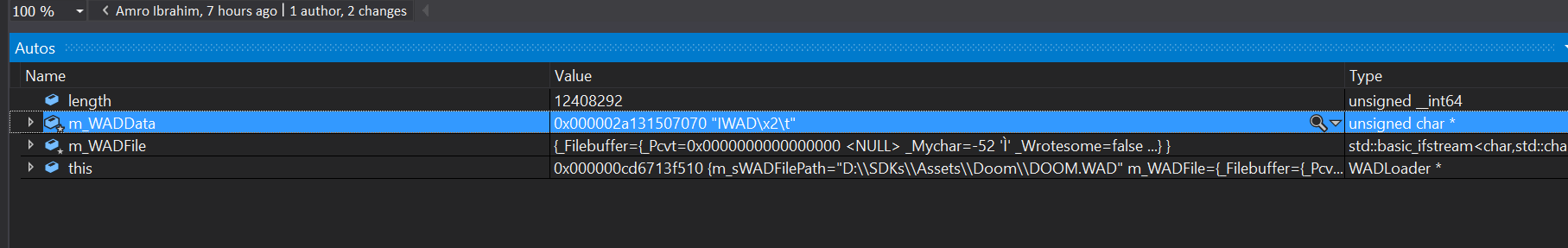
Oh! We got a console window that just opens for a few seconds! Nothing particularly useful ... does the program work? Idea! Let's take a look at the memory and see what is in it! Perhaps there we will find something special! To begin, place a breakpoint by double-clicking to the left of the line number. You should see something like this:
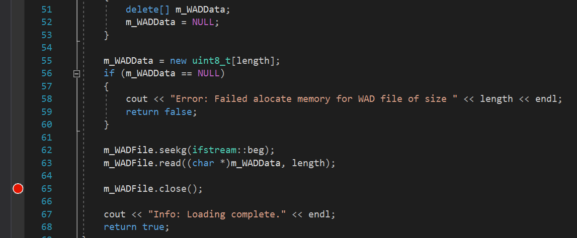
I placed a breakpoint immediately after reading all the data from the file to look at the memory array and see what was loaded into it. Now run the code again! In the automatic window, I see the first few bytes. The first 4 bytes say "IWAD"! Great, it works! I never thought that this day would come! So, okay, you need to calm down, there is still a lot of work ahead!
Read header
The total size of the header is 12 bytes (from 0x00 to 0x0b), these 12 bytes are divided into 3 groups. The first 4 bytes are a type of WAD, usually “IWAD” or “PWAD”. IWAD should be the official WAD released by ID Software, "PWAD" should be used for mods. In other words, this is just a way to determine if a WAD file is an official release, or is released by modders. Note that the string is not NULL terminated, so be careful! The next 4 bytes are unsigned int, which contains the total number of directories at the end of the file. The next 4 bytes indicate the offset of the first directory.
Let's add a structure that will store information. I will add a new header file and name it “DataTypes.h”. In it we will describe all the structs we need.
struct Header { char WADType[5]; // I added an extra character to add the NULL uint32_t DirectoryCount; //uint32_t is 4 bytes (32 bits) uint32_t DirectoryOffset; // The offset where the first directory is located. };
Now we need to implement the WADReader class, which will read data from the loaded WAD byte array. Oh! There is a trick here - WAD files are in big-endian format, that is, we will need to shift the bytes to make them little-endian (today, most systems use little endian). To do this, we will add two functions, one for processing 2 bytes (16 bits), the other for processing 4 bytes (32 bits); if we need to read only 1 byte, then nothing needs to be done.
uint16_t WADReader::bytesToShort(const uint8_t *pWADData, int offset) { return (pWADData[offset + 1] << 8) | pWADData[offset]; } uint32_t WADReader::bytesToInteger(const uint8_t *pWADData, int offset) { return (pWADData[offset + 3] << 24) | (pWADData[offset + 2] << 16) | (pWADData[offset + 1] << 8) | pWADData[offset]; }
Now we are ready to read the header: count the first four bytes as char, and then add NULL to them to simplify our work. In the case of the number of directories and their offset, you can simply use auxiliary functions to convert them to the correct format.
void WADReader::ReadHeaderData(const uint8_t *pWADData, int offset, Header &header) { //0x00 to 0x03 header.WADType[0] = pWADData[offset]; header.WADType[1] = pWADData[offset + 1]; header.WADType[2] = pWADData[offset + 2]; header.WADType[3] = pWADData[offset + 3]; header.WADType[4] = '\0'; //0x04 to 0x07 header.DirectoryCount = bytesToInteger(pWADData, offset + 4); //0x08 to 0x0b header.DirectoryOffset = bytesToInteger(pWADData, offset + 8); }
Let's put it all together, call these functions and print the results
bool WADLoader::ReadDirectories() { WADReader reader; Header header; reader.ReadHeaderData(m_WADData, 0, header); std::cout << header.WADType << std::endl; std::cout << header.DirectoryCount << std::endl; std::cout << header.DirectoryOffset << std::endl; std::cout << std::endl << std::endl; return true; }
Run the program and see if everything works!
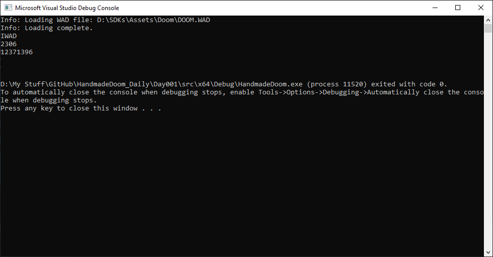
Fine! The IWAD line is clearly visible, but are the other two numbers correct? Let's try to read directories using these offsets and see if it works!
We need to add a new struct to handle the directory corresponding to the above options.
struct Directory { uint32_t LumpOffset; uint32_t LumpSize; char LumpName[9]; };
Now let's add the ReadDirectories function: count the offset and get them out!
In each iteration, we multiply i * 16 to go to the offset increment of the next directory.
Directory directory; for (unsigned int i = 0; i < header.DirectoryCount; ++i) { reader.ReadDirectoryData(m_WADData, header.DirectoryOffset + i * 16, directory); m_WADDirectories.push_back(directory); std::cout << directory.LumpOffset << std::endl; std::cout << directory.LumpSize << std::endl; std::cout << directory.LumpName << std::endl; std::cout << std::endl; }
Run the code and see what happens. Wow! A large list of directories.
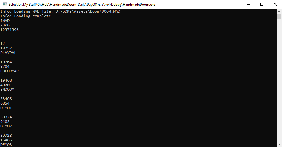
Judging by the name lump, we can assume that we managed to read the data correctly, but maybe there is a better way to check this. We will take a look at WAD Directory entries using Slade3.

It seems that the name and size of lump correspond to the data obtained using our code. Today we did a great job!
Other notes
- At some point, I thought it would be good to use vector for storing directories. Why not use Map? This will be faster than getting data by linear vector search. It is a bad idea. When using map, the order of directory entries will not be tracked, but we need this information to get the correct data.
And one more misconception: Map in C ++ is implemented as red-black trees with O (log N) search time, and iterations over map always give an increasing order of keys. If you need a data structure that gives the average time O (1) and the worst time O (N), then you have to use an unordered map. -
Loading all WAD files into memory is not an optimal implementation method.It would be more logical to simply read the directories into the memory header, and then return to the WAD file and load resources from disk.Hopefully someday we will learn more about caching.
DOOMReboot : completely disagree. 15 MB of RAM these days is a complete trifle, and reading from memory will be much faster than the voluminous fseek, which you will have to use after downloading everything that is necessary for the level. This will increase the download time by no less than one to two seconds (it takes me less than 20 ms to download all the time). fseek use the OS. Which file is most likely in the RAM cache, but it may not. But even if he is there, it is a big waste of resources and these operations will confuse many WAD readings from the point of view of the CPU cache. The best thing is that you can create hybrid boot methods and store WAD data for a level that fits in the L3 cache of modern processors, where the savings will be amazing.
Source
Source code
Basic Card Data
Having learned to read the WAD file, let's try to use the read data. It will be great to learn how to read mission data (world / level) and apply them. The “chunks” of these missions (Mission Lumps) should be something complex and tricky. Therefore, we will need to move and develop knowledge gradually. As a first small step, let's create something like an Automap function: a two-dimensional plan of a map with a top view. First, let's see what is inside the Mission Lump.
Card anatomy
Let's start again: the description of the DOOM levels is very similar to the 2D drawing, on which the walls are marked with lines. However, to obtain 3D coordinates, each wall takes the height of the floor and ceiling (XY is the plane along which we move horizontally, and Z is the height that allows us to move up and down, for example, by lifting on an elevator or jumping down from a platform. These three the coordinate components are used to render the mission as a 3D world, however, to ensure good performance, the engine has certain limitations: there are no rooms located one above the other at the levels and the player cannot look up and down. Another interesting feature: shells and Rock, for example, rockets, ascend vertically to hit a target located on a higher platform.
These curious features have caused endless holivars about whether the DOOM is a 2D or 3D engine. Gradually, a diplomatic compromise was reached, which saved many lives: the parties agreed on the designation “2.5D” acceptable to both.
To simplify the task and return to the topic, let's just try to read this 2D data and see if it can be used somehow. Later we will try to render them in 3D, but for now we need to understand how the individual parts of the engine work together.
After conducting research, I found out that each mission is composed of a set of "pieces". These “Lumps” are always presented in the WAD file of a DOOM game in the same order.
- Vertices (VERTEXES): The endpoints of walls in 2D. Two connected VERTEXs form one LINEDEF. Three connected VERTEX form two walls / LINEDEF, and so on. They can be simply perceived as the connection points of two or more walls. (Yes, most people prefer the plural “Vertices”, but John Carmack did not like it. According to merriam-webster , both options apply.
- LINEDEFS: lines forming joints between vertices and forming walls. Not all lines (walls) behave the same, there are flags that specify the behavior of such lines.
- SIDEDDEFS: in real life, the walls have two sides - we look at one, the second is on the other side. The two sides can have different textures, and SIDEDEFS is the lump containing the texture information for the wall (LINEDEF).
- SECTORS: sectors are the “rooms” obtained by the LINEDEF join. Each sector contains information such as floor and ceiling heights, textures, lighting values, special actions, such as moving floors / platforms / elevators. Some of these parameters also affect the way walls are rendered, for example, the level of illumination and the calculation of texture mapping coordinates.
- SSECTORS: (subsectors) form convex areas within a sector that are used in rendering along with the BSP bypass, and also help determine where a player is at a particular level. They are quite useful and are often used to determine a player’s vertical position. Each SSECTOR consists of connected parts of a sector, for example, of walls forming an angle. Such parts of the walls, or “segments,” are stored in their own Lump called ...
- SEGS: wall parts / LINEDEF; in other words, these are the “segments” of the wall / LINEDEF. The world is rendered bypassing the BSP tree to determine which walls to draw first (the very first are the closest). Although the system works very well, it causes linedefs to often split into two or more SEGs. Such SEGs are then used to render walls instead of LINEDEF. The geometry of each SSECTOR is determined by the segs contained in it.
- NODES: A BSP node is a binary tree structure node that stores subsector data. It is used to quickly determine which SSECTOR (and SEG) are in front of the player. Eliminating SEGs located behind the player, and therefore invisible, allows the engine to focus on potentially visible SEGs, which significantly reduces rendering time.
- THINGS: Lump called THINGS is a list of scenery and mission actors (enemies, weapons, etc.). Each element of this lump contains information about one instance of the actor / set, for example, the type of the object, the point of creation, direction, and so on.
- REJECT: this lump contains data about which sectors are visible from other sectors. It is used to determine when a monster learns about a player’s presence. It is also used to determine the distribution range of sounds created by the player, for example, shots. When such a sound is able to be transmitted to the sector of the monster, he can find out about the player. The REJECT table can also be used to speed up the recognition of collisions of weapon shells.
- BLOCKMAP: player collision recognition information and THING motion. Consists of a grid covering the geometry of the entire mission. Each grid cell contains a list of LINEDEFs that are inside or intersect it. It is used to significantly speed up the recognition of collisions: collision checks are required only for a few LINEDEF per player / THING, which significantly saves computing power.
When generating our 2D map, we will focus on VERTEXES and LINEDEFS. If we can draw the vertices and connect them with the lines given by linedef, then we need to generate a 2D model of the map.
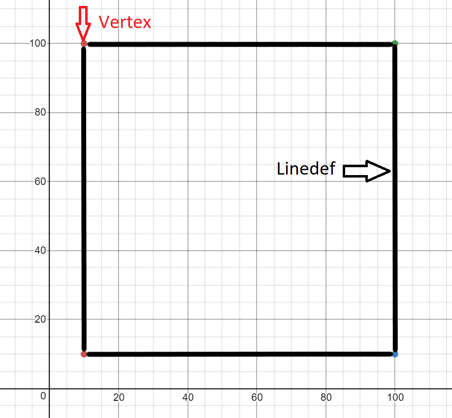
The demo card shown above has the following characteristics:
- 4 peaks
- vertex 1 in (10.10)
- top 2 at (10,100)
- top 3 at (100, 10)
- peak 4 in (100,100)
- 4 lines
- line from top 1 to 2
- line from top 1 to 3
- line from top 2 to 4
- line from top 3 to 4
Vertex format
As you might expect, the vertex data is very simple - just x and y (point) of some coordinates.
| Field size | Data type | Content |
|---|---|---|
| 0x00-0x01 | Signed short | Position X |
| 0x02-0x03 | Signed short | Y position |
Linedef format
Linedef contains more information; it describes the line connecting the two vertices and the properties of this line (which will later become a wall).
| Field size | Data type | Content |
|---|---|---|
| 0x00-0x01 | Unsigned short | Starting peak |
| 0x02-0x03 | Unsigned short | Final peak |
| 0x04-0x05 | Unsigned short | Flags (see below for more details) |
| 0x06-0x07 | Unsigned short | Line Type / Action |
| 0x08-0x09 | Unsigned short | Sector label |
| 0x10-0x11 | Unsigned short | Front sidedef (0xFFFF - no side) |
| 0x12-0x13 | Unsigned short | Rear sidedef (0xFFFF - no side) |
Linedef flag values
Not all lines (walls) are drawn. Some of them have special behavior.
| Bit | Description |
|---|---|
| 0 | Blocks the way for players and monsters |
| one | Block monsters |
| 2 | Double sided |
| 3 | The upper texture is disabled (we'll talk about this later) |
| four | The bottom texture is disabled (we'll talk about this later) |
| 5 | Secret (shown on the map as a one-sided wall) |
| 6 | Obstructs the sound |
| 7 | Never shown on autocard |
| 8 | Always shown on autocard |
Goals
- Create a Map class.
- Read vertex data.
- Read linedef data.
Architecture
First, let's create a class and call it map. In it we will store all the data associated with the card.
For now, I plan to only store vertices and linedefs as a vector, so that I can apply them later.
Also, let's complement WADLoader and WADReader so that we can read these two new pieces of information.
Coding
The code will be similar to the WAD reading code, we will only add a few more structures, and then fill them with data from WAD. Let's start by adding a new class and passing the map name.
class Map { public: Map(std::string sName); ~Map(); std::string GetName(); // Incase someone need to know the map name void AddVertex(Vertex &v); // Wrapper class to append to the vertexes vector void AddLinedef(Linedef &l); // Wrapper class to append to the linedef vector protected: std::string m_sName; std::vector<Vertex> m_Vertexes; std::vector<Linedef> m_Linedef; };
Now add structures to read these new fields. Since we have already done this several times, just add them all at once.
struct Vertex { int16_t XPosition; int16_t YPosition; }; struct Linedef { uint16_t StartVertex; uint16_t EndVertex; uint16_t Flags; uint16_t LineType; uint16_t SectorTag; uint16_t FrontSidedef; uint16_t BackSidedef; };
Next, we need a function to read them from WADReader, it will be close to what we did earlier.
void WADReader::ReadVertexData(const uint8_t *pWADData, int offset, Vertex &vertex) { vertex.XPosition = Read2Bytes(pWADData, offset); vertex.YPosition = Read2Bytes(pWADData, offset + 2); } void WADReader::ReadLinedefData(const uint8_t *pWADData, int offset, Linedef &linedef) { linedef.StartVertex = Read2Bytes(pWADData, offset); linedef.EndVertex = Read2Bytes(pWADData, offset + 2); linedef.Flags = Read2Bytes(pWADData, offset + 4); linedef.LineType = Read2Bytes(pWADData, offset + 6); linedef.SectorTag = Read2Bytes(pWADData, offset + 8); linedef.FrontSidedef = Read2Bytes(pWADData, offset + 10); linedef.BackSidedef = Read2Bytes(pWADData, offset + 12); }
I think there is nothing new for you here. And now we need to call these functions from the WADLoader class. Let me state the facts: the sequence of lumps is important here, we will find the name of the map in the lump directory, followed by all the lumps associated with the maps in the given order. To simplify our task and not to track the lumps indices separately, we will add an enumeration that allows us to get rid of magic numbers.
enum EMAPLUMPSINDEX { eTHINGS = 1, eLINEDEFS, eSIDEDDEFS, eVERTEXES, eSEAGS, eSSECTORS, eNODES, eSECTORS, eREJECT, eBLOCKMAP, eCOUNT };
I will also add a function to search for a map by its name in the directory list. Later, we are likely to increase the performance of this step by using the map data structure, because there are a significant number of records here, and we will have to go through them quite often, especially at the beginning of loading resources such as textures, sprites, sounds, etc.
int WADLoader::FindMapIndex(Map &map) { for (int i = 0; i < m_WADDirectories.size(); ++i) { if (m_WADDirectories[i].LumpName == map.GetName()) { return i; } } return -1; }
Wow, we're almost done! Now, let's just count VERTEXES! I repeat, we have already done this before, now you must understand this.
bool WADLoader::ReadMapVertex(Map &map) { int iMapIndex = FindMapIndex(map); if (iMapIndex == -1) { return false; } iMapIndex += EMAPLUMPSINDEX::eVERTEXES; if (strcmp(m_WADDirectories[iMapIndex].LumpName, "VERTEXES") != 0) { return false; } int iVertexSizeInBytes = sizeof(Vertex); int iVertexesCount = m_WADDirectories[iMapIndex].LumpSize / iVertexSizeInBytes; Vertex vertex; for (int i = 0; i < iVertexesCount; ++i) { m_Reader.ReadVertexData(m_WADData, m_WADDirectories[iMapIndex].LumpOffset + i * iVertexSizeInBytes, vertex); map.AddVertex(vertex); cout << vertex.XPosition << endl; cout << vertex.YPosition << endl; std::cout << std::endl; } return true; }
Hmm, it looks like we are constantly copying the same code; it may be necessary to optimize it in the future, but for now you will implement ReadMapLinedef yourself (or look at the source code from the link).
Final touches - we need to call this function and pass the map object to it.
bool WADLoader::LoadMapData(Map &map) { if (!ReadMapVertex(map)) { cout << "Error: Failed to load map vertex data MAP: " << map.GetName() << endl; return false; } if (!ReadMapLinedef(map)) { cout << "Error: Failed to load map linedef data MAP: " << map.GetName() << endl; return false; } return true; }
Now let's change the main function and see if everything works. I want to load the E1M1 map, which I will transfer to the map object.
Map map("E1M1"); wadloader.LoadMapData(map);
Now let's run it all. Wow, a bunch of interesting numbers, but are they true? Let's check!
Let's see if slade can help us with this.
We can find the map in the slade menu and look at the details of lumps. Let's compare the numbers.
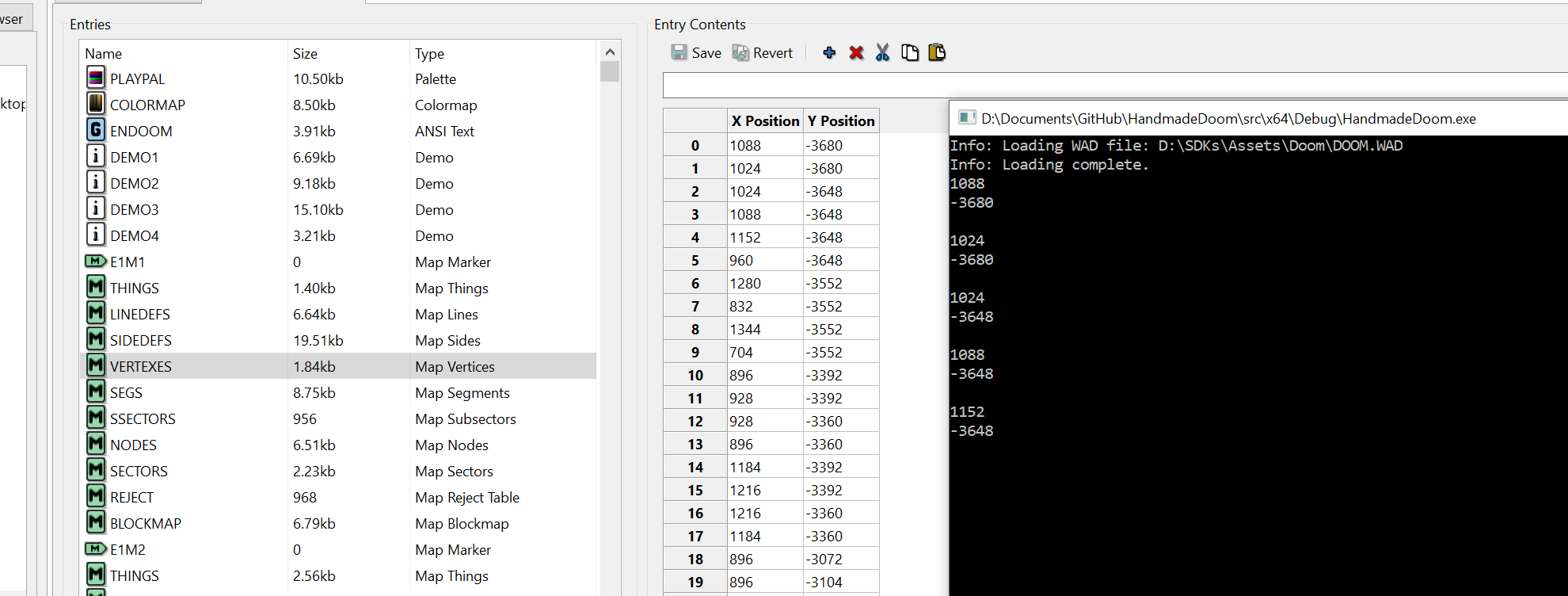
Fine!
What about Linedef?

I also added this enumeration, which we will try to use when rendering the map.
enum ELINEDEFFLAGS { eBLOCKING = 0, eBLOCKMONSTERS = 1, eTWOSIDED = 2, eDONTPEGTOP = 4, eDONTPEGBOTTOM = 8, eSECRET = 16, eSOUNDBLOCK = 32, eDONTDRAW = 64, eDRAW = 128 };
Other notes
In the process of writing the code, I mistakenly read more bytes than necessary, and received incorrect values. For debugging, I started looking at the WAD offset in memory to see if I was at the right offset. This can be done using the Visual Studio memory window, which is a very useful tool for tracking bytes or memory (you can also set breakpoints in this window).
If you do not see the memory window, go to Debug> Memory> Memory.
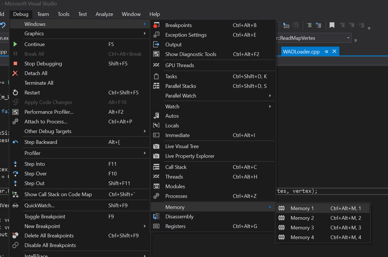
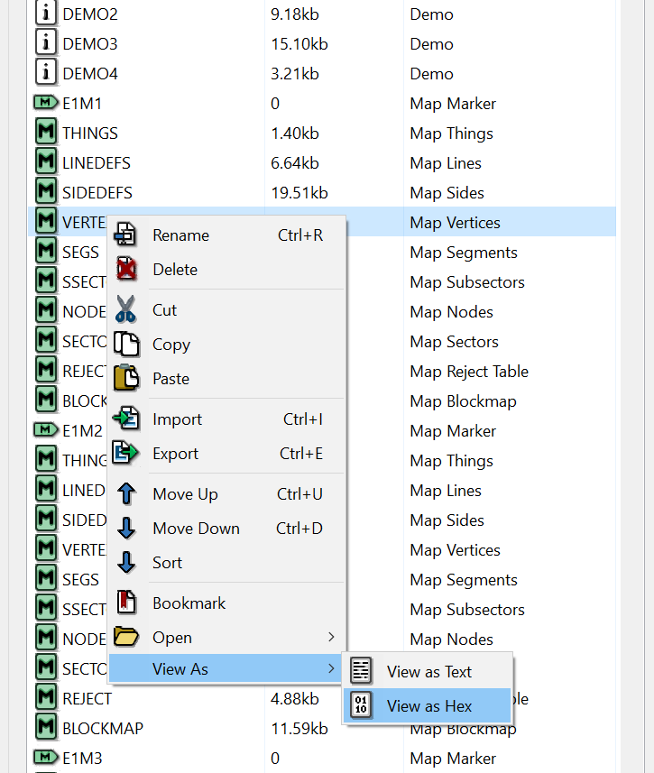
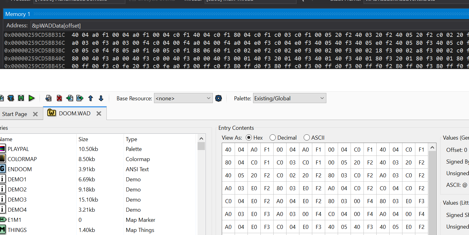
Now we see the values in memory in hexadecimal. These values can be compared with the hex display in slade by right-clicking on any lump and displaying it as hex.
Compare them with the address of the WAD loaded into memory.
And the last thing for today: we saw all these vertex values, but is there an easy way to visualize them without writing code? I do not want to waste time on this, just to find out that we are moving in the wrong direction.
Surely someone already created a plotter. I googled “draw points on a graph” and the first result was the Plot Points website - Desmos . On it you can paste numbers from the clipboard, and he will draw them. They must be in the format "(x, y)". To get it, just change the display function a little.
cout << "(" << vertex.XPosition << "," << vertex.YPosition << ")" << endl;
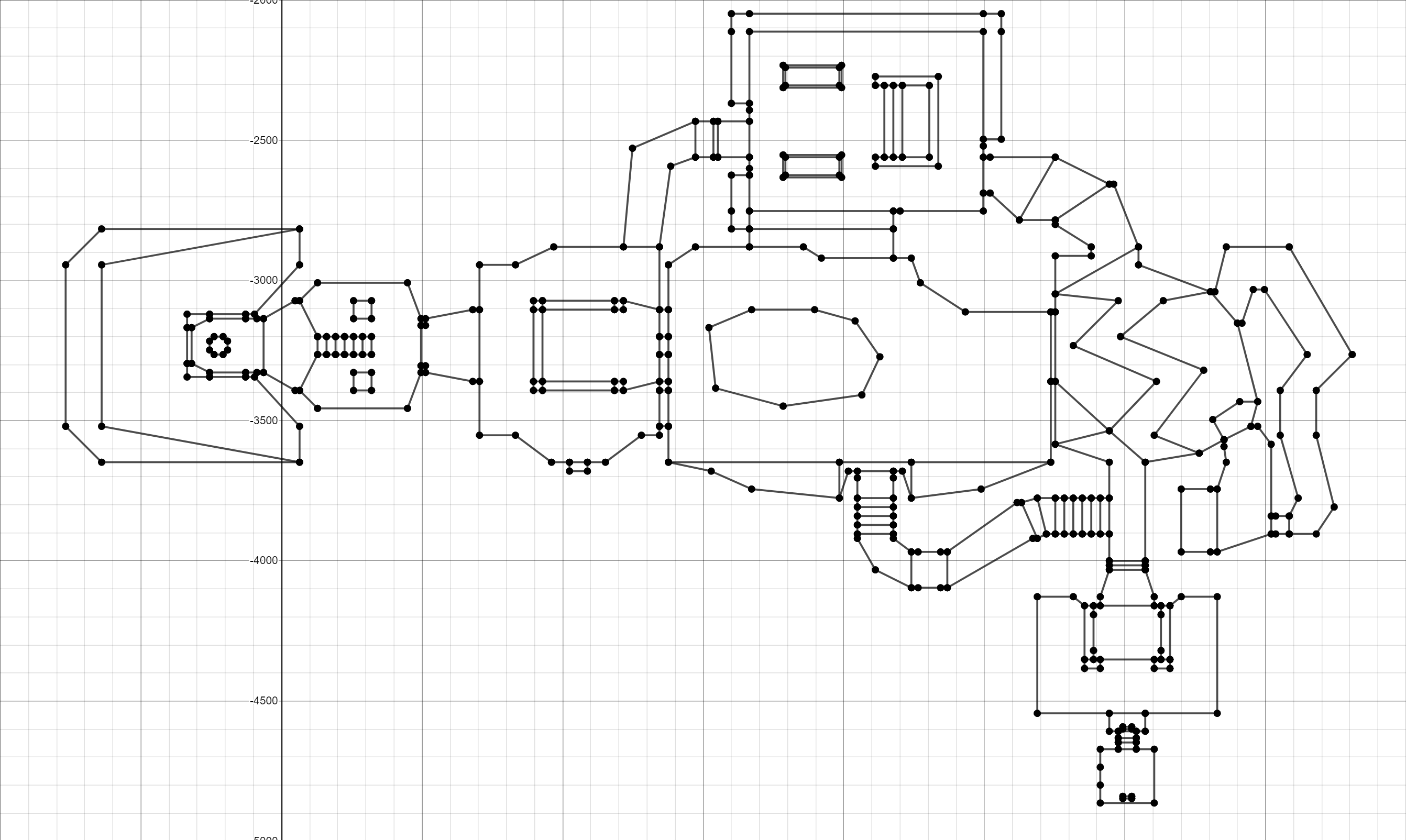
Wow! It already looks like an E1M1! We have achieved something!
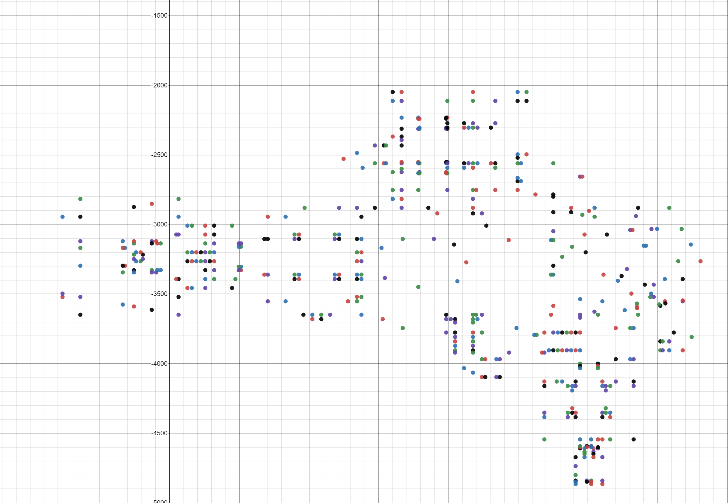
If you are lazy to do this, here is a link to a dotted chart: Plot Vertex .
But let's take one more step: after a bit of work, we can connect these points based on linedefs.
Here is the link: E1M1 Plot Vertex
Source
Source code
Reference materials
Doom Wiki
ZDoom Wiki