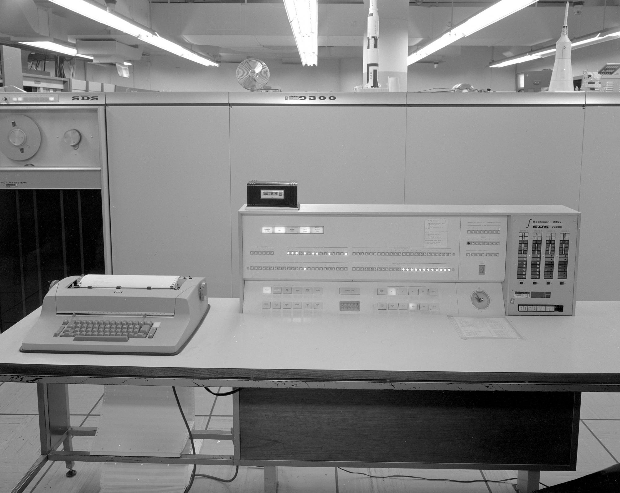
Hybrid Simulation Lab Equipment. The photo shows the SDS 9300 control panel, which, together with several analog computers, worked out simulations of the command module and the lunar module.
Years before Apollo 11, when the control system was being developed, they thought of the embedded software as something that could be done last: “Hal will do it,” they said. In fact, dozens of people, and hundreds of support staff did this, but Hal Laning first had to figure out how to organize the numerous software functions so that they could be performed almost simultaneously in real time on the on-board computer of the spacecraft, which has limited size and speed .
Hal's architecture avoided the pitfalls of the operating system, in which calculations should be clearly divided between time periods. Such systems are rather difficult to implement, because tasks can change arbitrarily. When tasks are added or changed during the development process, a change in task planning may be required. The worst thing is that the existing operating system of the on-board computer is very fragile, in the sense that it completely fails if the task takes more time than was allocated.
Instead, Leining developed a system in which program functions are distributed in the form of “tasks,” which can be any size that will be required to perform these functions. Each task is assigned a priority. The operating system always performs the task with the highest priority. If a task with a low priority is performed, and a task with a high priority is assigned at this time, then a task with a low priority will be suspended until the task with a high priority is completed. Such a system gives us the illusion that tasks are performed simultaneously, although in reality, of course, tasks are performed in turn. Such a system is not deterministic, but its functions are understandable and can be verified, and it increases reliability, security, flexibility in use, and, in particular, ease of development.
Executive ( the real-time operating system AGC and LGC. Approx. Transl. ) Organized the execution of tasks in such a way that each task retained its state in the form of a set of registers, and the state was maintained while the task was being performed with high priority. LGC contains an array of eight sets of 12 registers each, 15 bits in a register. A set of registers of this size is sufficient to perform many tasks, but tasks that use the interpreter (a built-in interpreting language for tasks that operate with double precision numbers. Approx. Transl. ) To perform vector and matrix calculations require more space. For such tasks, a separate array of 43 registers is allocated. LGC contains five such arrays (Vector Accumulator, VAC).
With such a limited set of arrays to maintain the context of tasks, launching tasks for execution should be done very carefully. Functions that are performed sequentially one after the other were combined into one task. The big task of SERVICER was active during the entire landing phase and other phases of the flight with the engine turned on, and it included navigation using accelerometers, equations of motion, throttle control of the engine, data on the position of the ship, other data on the display, and each the function used the output of the previous ones.
The number of available register arrays and VAC limits the number of tasks that can be queued for execution by eight, of which up to five can use VAC arrays. During normal operation, the number of running tasks remains constant, although tasks launched for a single execution, or asynchronously, can cause fluctuations in system load.
However, if the number of started tasks is more than completed, the number of used register arrays and VAC increases. If this situation lasts long enough, their number runs out, and the request to launch the next task cannot be satisfied.
We’ll come back a year earlier, before the launch of Apollo 11, when we, the software engineers, thought that we already had enough things to do, and we were required to write software for landing on the Moon in such a way that it could literally be turned off and back on without interrupting the landing process and other vital maneuvers! This was called "restart protection." In addition to power interference, other factors can cause the system to restart. Restart occurs if the hardware thinks that the program crashed in an infinite loop, or if a parity error occurred while reading the ROM, or for several other reasons.
Protection against restart was implemented by registering “waypoints” at suitable points in the program, arranged in such a way that returning to the last “waypoint” did not cause an error, as shown in the following example:
NEW_X = X + 1
X = NEW_X
Obviously, without registering the waypoint, executing this code a second time will cause the X increment again.
After the restart, such a program resumes its work. Each task starts with the last registered waypoint. if several copies of the same task were in the queue, only the last one is resumed. Some tasks do not have vital status, and are not protected from restart. They just disappear.
Restart protection worked very well. There was a button on the control panel of our hybrid simulator in Cambridge that caused the restart of the AGC. When testing software, we sometimes pressed this button at random times, almost hoping that the failure would lead us to another bug. Invariably, each time the protection against restart was triggered, and the work continued without stopping.
(The hybrid simulator contained an SDS 9300 digital computer and a Beckmann analog computer, a real AGC computer, and realistic models of the command and moon module cockpits.)
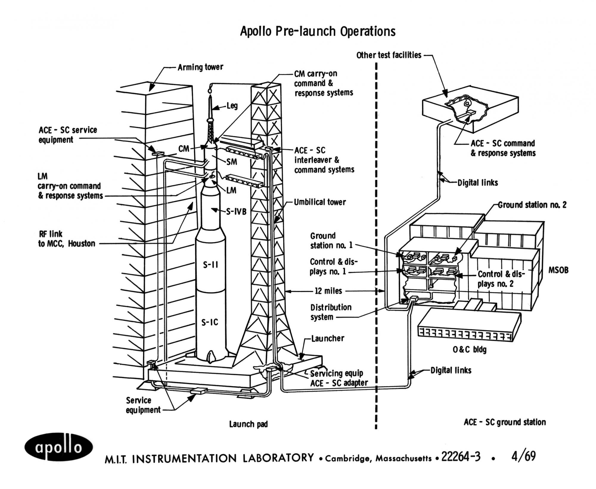
Prelaunch preparation of Apollo.
Not only iron could cause a restart, it could be called programmatically if the program reached a point at which the computer did not know how to continue executing the program. This happened when transferring control under the BAILOUT tag in the Alarms and Aborts module. The call was accompanied by an error code.
These actions were performed by the Executive system, if resources were exhausted. If the task cannot be set due to the fact that there are no free arrays to save registers, Executive called BAILOUT with error code 1202. If there was no free VAC, then BAILOUT with code 1201 was called.
Not all functions performed by LGC were performed as "tasks." In addition to them, there were hardware interrupts that could occur at any time (if they were not explicitly prohibited) that performed high-priority functions, interrupts were assigned to certain devices, including digital autopilot, “uplink” and “downlink” ( transmission and reception device) data on the radio channel with the Earth. approx. transl. ) and the keyboard.
Other interrupts could be used to execute pieces of code that must be executed at a specific time. Such functions were called tasks, and they were scheduled in a subroutine called WAITLIST. "Tasks" were supposed to have a very short lead time.
While “tasks” were planned for execution with a certain priority, “tasks” were planned for launch at a certain time. Tasks and tasks were often shared. The task could be launched to read the sensor readings, which should be read at a strictly defined time, and the task, in turn, launched a task with a certain priority for processing these readings.
When Hal Lane designed Executive and Waitlist in the mid-1960s, he did everything from scratch, without relying on any examples. And his principles are true today. The distribution of functions by a limited number of asynchronous processes, under the control of an executive environment with preemptive multitasking based on time intervals and priorities, all this still underlies modern real-time computer systems for space applications.
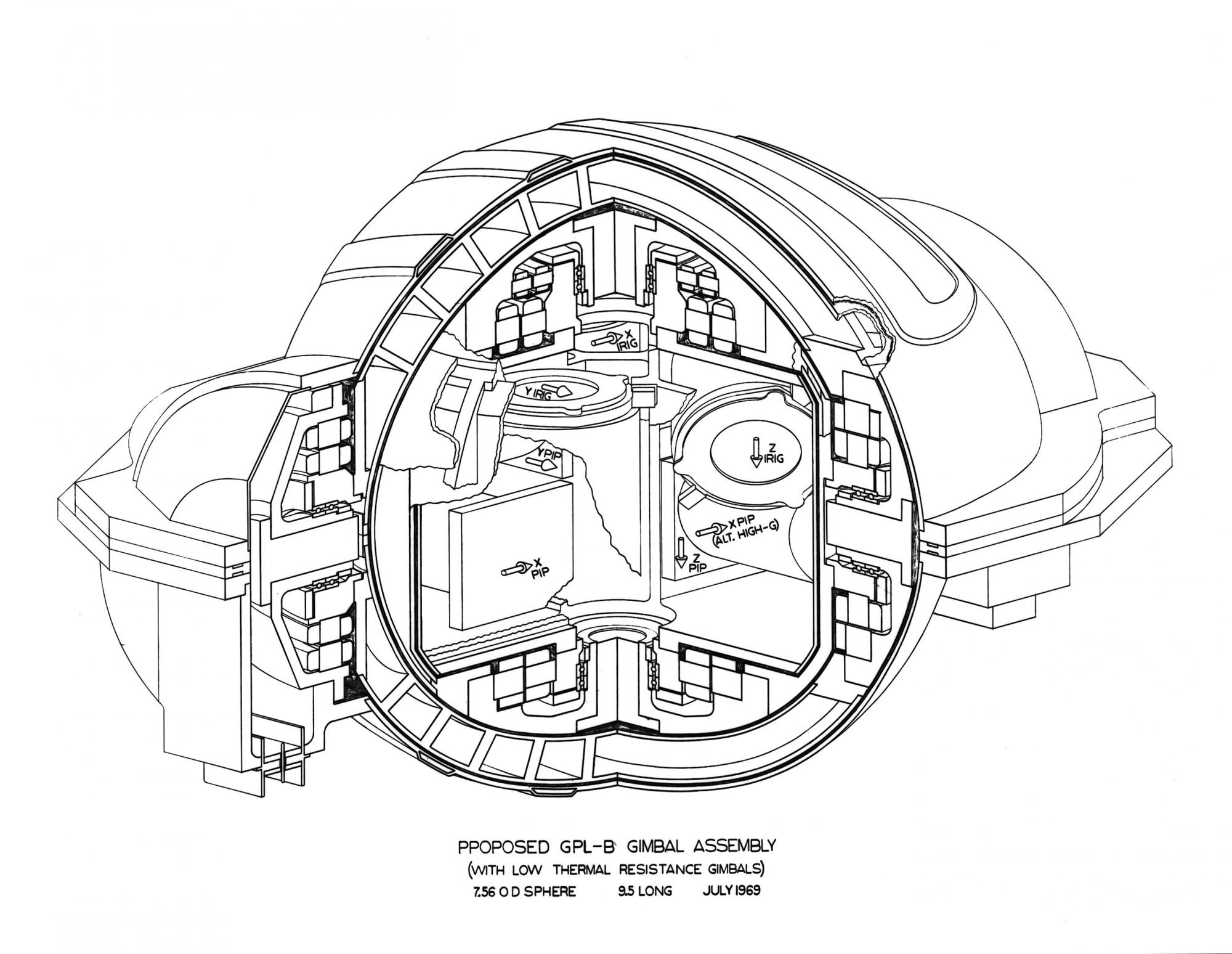
Assembly of gyroscopes.
* * *
To understand the root cause of the alarms on Apollo 11 during the descent, it is necessary to consider the approach procedure to the command module, which follows after the rise of the lunar module from the lunar surface to the lunar orbit. Just as we use a landing radar to measure altitude and speed relative to the lunar surface when landing on the moon, approaching the command module in lunar orbit requires measuring distance, speed and direction relative to the second ship using the approach radar.
The proximity radar has several operating modes that are set by the mode switch. These modes are as follows: SLEW, AUTO, and LGC. In SLEW and AUTO modes, the radar operates under command control, regardless of LGC. This mode of operation could be used during take-off and approach in the event of a failure of the main navigation system. In SLEW mode, the radar antenna is manually guided, the rest of the time it is stationary. When the antenna is aimed at the target, you can switch the mode to AUTO (auto tracking) and it will track the target. The proximity radar measures distance and speed, and the angles of rotation of the shafts at which the antenna rotates are displayed on the cockpit displays and on the indicators in the form of vertical scales. Also, distance and speed data came into the abort guidance system (AGS), a computer with only 6144 words of memory, which duplicated the main PGNS system when landing on the moon and taking off from the moon.
(The names of the three rapprochement radar operating modes were a source of embarrassment for some commentators. At the request of the crew, the designations were changed after the mission LM-1 and before the mission landing on the moon. The mode that Apollo 11 called LGC was formerly called AUTO. The mode that it was called AUTO on Apollo 11, formerly called MANUAL. The name of the SLEW mode remained unchanged. Although this in no way contributed to the problem on Apollo 11, the internal LUMINARY documentation in the section relating to discrete channel 33, at that time still called re LGC benchmark with the proximity radar turned on by RR AUTO-POWER ON.)
If the PGNS system worked (as it actually was), the LGC controlled the radar, in which case the proximity radar mode switch was set to LGC. The electronics of the radar interface allowed the software to obtain data on the distance and speed measured by the radar, as well as the angles of the antenna shaft, from which the direction to the target can be found. The LGC program used this information to drive the LGC closer to the command module.
It turned out that the approach radar can also work during the descent, and this was done during the descent of Apollo 11. Crew instructions required that the radar be turned on immediately before the start of the P63 phase and remain in SLEW or AUTO mode for the entire landing maneuver.
Many explanations were given as to why the radar was set up in this way to land on the moon. For example, some people in Houston may have considered a fancy landing monitoring scheme by comparing radar data with a graph of expected readings. However, there is a simpler explanation: the radar was turned on before landing only in order to stay warm in case of an accident during interruption, and was in AUTO mode (if the lunar module was in a position that allows you to track the command module) or SLEW (at other times), just to prevent useless movement of the antenna.
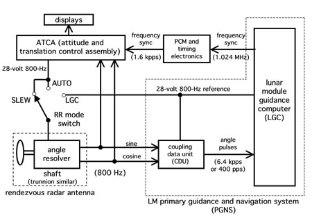
Figure 7. PGNS, ATCA, and Proximity Radar Interfaces
This problem was often attributed (including by the author earlier) simply as an error in the checklist. This is an inaccurate wording, just as it is inaccurate to call a premature monitor shutdown
delta-V engine of the lunar module is a "computer error", while in fact the error was in the documentation. In fact, the position of the Apollo 11 proximity radar switch should not have caused any problems. But from here you can trace another case of errors in the documentation.
Years before, documentation was written on the interface control document (ICD), which defines the electrical interface between the PGNS and the ATCA (attitude and translation control assembly), which was supplied by Grumman Aerospace, the company that built the landing module. ICD determined that the 28V power supply circuits with a frequency of 800 Hz in two systems should be aligned in frequency, but it is not written that they should be synchronized in phase. In fact, the two systems were frequency aligned with the “frequency sync” signal sent by LGC. They had a constant phase relationship. However, the phase between the two voltages was a completely random variable, depending on the moment at which the LGC, which was always powered after ACTA, began to send a synchronization signal. These interfaces are shown in fig. 7.
A problem with the 800 Hz phase was detected when testing the LM-3's landing module and is documented, but has never been fixed. As a result, when the radar mode switch was in the AUTO or SLEW position, the rotary mechanism of the radar was excited by a 800 Hz signal from the ATCA, which with high probability does not coincide in phase with the 800 Hz signal, which is used as a reference in CDUs that convert signals from a mechanism for turning into data for the computer, and decrementing (or decrementing) the counters in the computer that tell the program how the antenna is rotated.
On Apollo 11, however, CDUs worked differently. Since they took a separately generated voltage as a reference signal, the signals of the antenna angle sensors received by the CDU showed an unknown angle. The error was greatest if the phase difference was close to 90 or 270 degrees, and Apollo 11, obviously, hit one of these interesting points. In response, the CDU began to increment or decrement LGC counters at an almost constant speed, about 6400 pulses per second for each of the corners. This happened every time the switch was in SLEW or AUTO mode, regardless of whether the proximity radar was turned on.
The counters of the CDU interface in LGC were incremented or decremented by external signals that were processed in the computer. This was time consuming, in this case one memory cycle of 11.7 μs each. If the counters incremented at maximum speed, it took about 15% of the total time (this stray time is called TLOSS). We currently provide a conservative estimate of the time spent 13%, which is consistent with the observed behavior.
After the flight of Apollo 11, Grumman engineers conducted tests in an attempt to reproduce the computer behavior observed in flight. They confirmed that even in the worst case, CDUs could not send pulses at maximum speed. They came to the conclusion that the maximum computer load with these meters (TLOSS) could be 13.36%. During the simulation, errors similar to those that occurred in flight were reproduced. Thus, the quoted TLOSS value is the best documented estimate of Apollo 11 computer load. [Clint Tillman, “Simulating the RR-CDU Interface When the RR is in the SLEW or AUTO (not LGC) Mode in the FMES / FCI Laboratory,” August 9 , 1969]
I am indebted to the lunar module guidance system expert George Silver for his patient explanations of the lunar module rendezvous radar interface. He played a central role in the Apollo 11 mission. At the time of launch, he was at Cape Canaveral, then flew to Boston, to Cambridge, to take on duty to monitor take-off from the Moon. He watched the moon landing at home on TV on July 20. He heard the sounds of alarms, guessed that something was taking up the computer’s time, and recalled a case he had seen while testing LM-3 systems, when the proximity radar caused frantic activity of the counters. After some further analysis by the Cambridge mission monitoring team, Silver finally contacted the MIT in Houston on the morning of July 21, less than an hour before take-off from the moon.
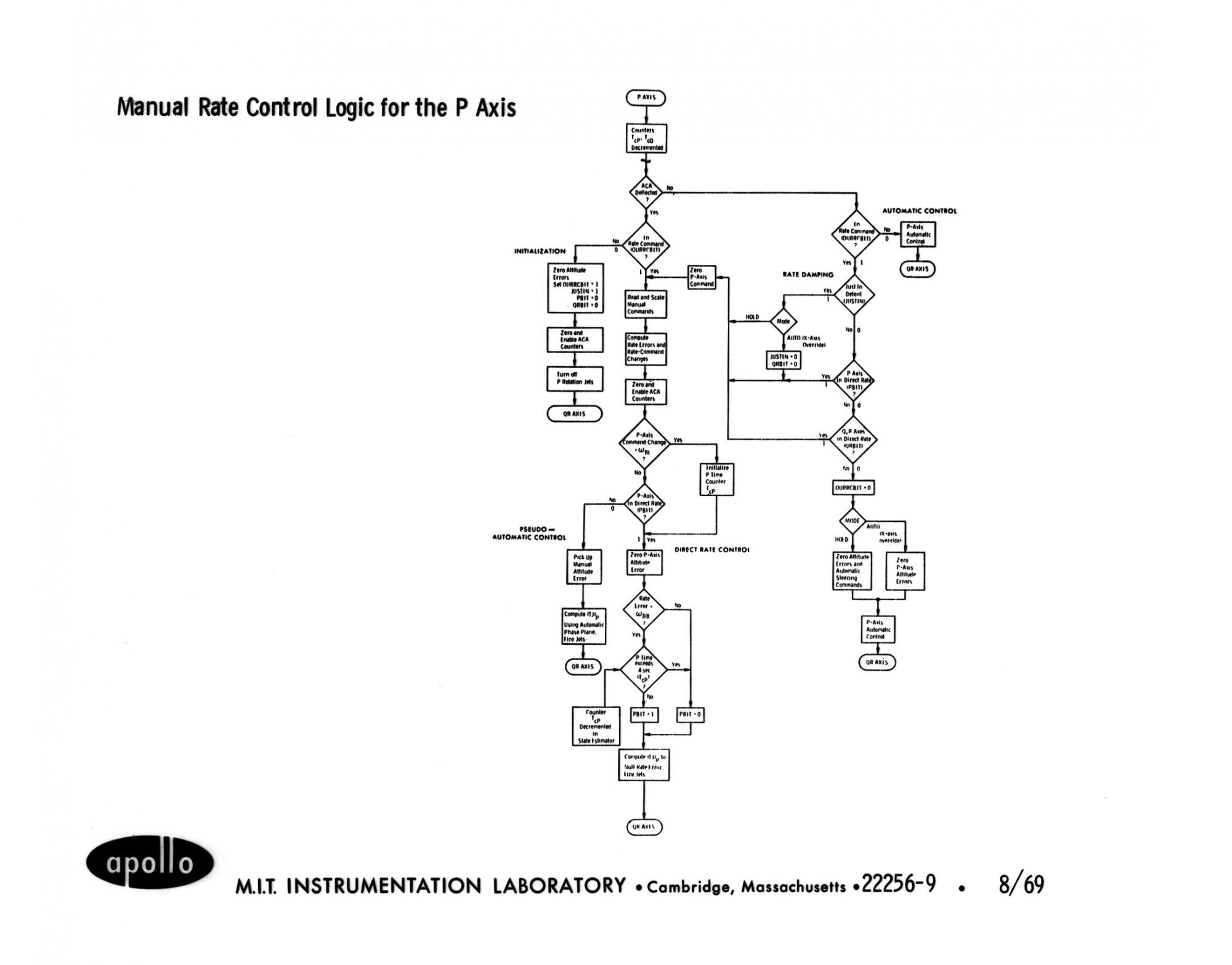
Manual control fragment
* * *
Landing on the moon was the most intense phase of flight. The landing control system had to achieve a goal with certain coordinates, having a certain speed, acceleration, degree of jerking (degree of change / acceleration). Klumpp called the jerk change rate “snap,” and the next two derivatives were called crackle and pop. In the phase of visibility ( that is, when the surface of the moon was visible in porthole of the ship. approx. transl. ) the program allowed the crew to change the landing site. The throttle was controlled continuously. Navigation included measurements using the landing radar. Fig. 8. shows a typical load profile between the choice of phase P63 and touching the surface of the moon.

Fig. 8: Load during landing (simulator data)
Even under these conditions, we tried to make our programs fast enough to have enough time in case of a large TLOSS. The main limitation was the two-second period, which was built into the “average-G” program used during the flight phase.This was the period during which the READACCS task read the readings of the accelerometers and launched the SERVICER task, which used these values as initial data for a new iteration of the trajectory calculations, throttling the engine, determining the position of the ship and displaying it on the display. During the landing, the degree of computer load simply showed how much time was spent on tasks and interruptions during each two-second period.
During the braking phase, until the landing radar saw the surface, the reserve time was at least 15%. After the radar is put into operation, additional calculations begin, associated with the transfer of coordinates from the radar reference system to the coordinate system for navigation, which reduce the margin by 13%. When the display starts (verb 16, noun 68), the margin decreases to 10% or lower. Baz Aldrin was perceptive when he said after signal 1202, "it seems he appeared when we entered 1668" [16].
When the margin is 10%, and 13% is taken away, LGC does not have enough processor time to perform all the required functions. Thanks to the flexibility of Executive design, and unlike what would happen with rigid architecture, there was no disaster.
Table 1. Tasks active when landing on the moon.
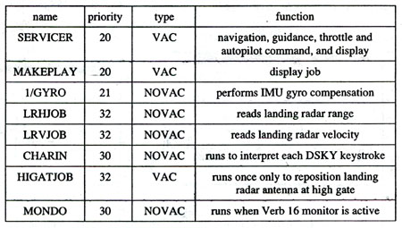
Table 1 lists the tasks that are active when landing Apollo 11. SERVICER has the lowest priority, and runs the longest. High priority tasks can stop the SERVICER, but they have a relatively short lead time.
Since SERVICER had a low priority due to its large size, it broke down due to lack of computing time. With a negative margin in time, SERVICER did not manage to give an answer when the READACCS, which started according to the schedule, started again and started SERVICER again. Since the previous copy of SERVICER did not finish the calculation, it did not free the register and VAC arrays, and READACCS called FINDVAC so that Executive allocated a new register and VAC array and started SERVICER. This SERVICER did not finish work on time either. After a short cycle of such operations, the register and VAC arrays ended. When the following request came to Executive, BAILOUT was called with the code 1201 or 1202.
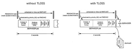
Fig. 9: SERVICER operation without and with TLOSS
Fig.Figure 9 shows how SERVICER behaves with a strong TLOSS, and in fig. Figure 10 shows a comparison of the registers and VAC usage graphs during normal operation and with strong TLOSS, at which a restart occurs.
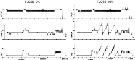
Fig.10. The effect produced by TLOSS on Executive and Waitlist resources during the landing on the Moon (simulator data begins with phase P63 before receiving speed data from the radar and ends with landing [17].)
An interesting effect of this sequence of events during phase P63 , was that the problem eliminated itself. A software restart restored only the most recent copy of the SERVICER task, and deleted all incomplete copies of SERVICER. In addition, he completed all functions that do not have restart protection because they are not critical, including the DELTAH monitor (verb 16, noun 68). This caused the display to switch from “noun 68” to “noun 63” after two alarms in P63.
The restart protection system was originally developed due to possible hardware failures and provided a reduction in computational load with a large TLOSS. The real-time system developed by us turned out to be fault tolerant in certain conditions.
During the P64 phase, the situation was different. In addition to the usual equations of motion, additional processing was added that included the ability to reassign the landing site. Additional software features leave a margin of time less than 10%. Alarms continued to arise. Three alarms of 1201 and 1202 occurred within 40 seconds. Each time, the software restarted, clearing the task queue, but could not reduce the load.
Mission time 102: 43: 08, anticipating the next alarm, Armstrong switched the autopilot from AUTO to ATT HOLD mode, weakening the computational load, and then entered the semi-manual P66 mode, in which the computer load was low. After 2 minutes and 20 seconds of maneuvering in phase P66, the lunar module sat down.