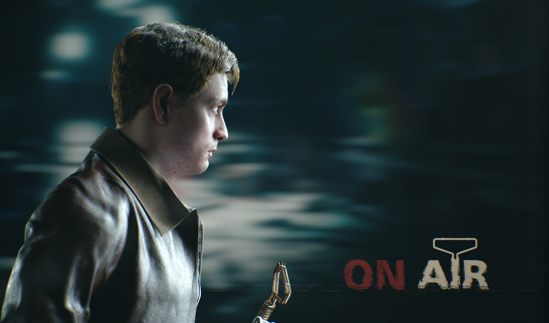
The game tells about the mysterious events that happened with the main character, who accidentally stayed at the American hotel Algol. This incident will completely change his life and make him face the unknown.
This is our first game project and in it we try to achieve the maximum realism of the characters, convey their emotions and character. Therefore, to create them, it was decided to use face scanning technology. As part of the objectives of the project, we need two degrees of detail for the characters: for rendering - for cinematics and low poly - for use in the game itself.
The game On Air is developed on the Unreal Engine 4. We plan to write several articles in which we will describe in detail the stages of character preparation.
At the moment, we are creating a demo version of the game, which will soon appear in Steam. In this article I will talk about the initial stage of creating the face of the main character of our game.

Part 1
The image below shows some of the emotions that we received after processing the scans.

Basically they are exaggerated and do not seem realistic. This was done on purpose. The fact is that the principle of blending the “Blend shapes” forms the basis of this method of creating a face. That is, each of these emotions will be applied not in a “pure” form, but in combination with others. I will tell you more about this at the very end of the article. First, you need to figure out what to do with the scanned head and how we can use it. Obviously, the topology of the scan does not allow it to be used as a model, but by baking the normal map we get the main features of the face, wrinkles, pores, bumps or scars. Also from the scan we can extract the texture of the base color.
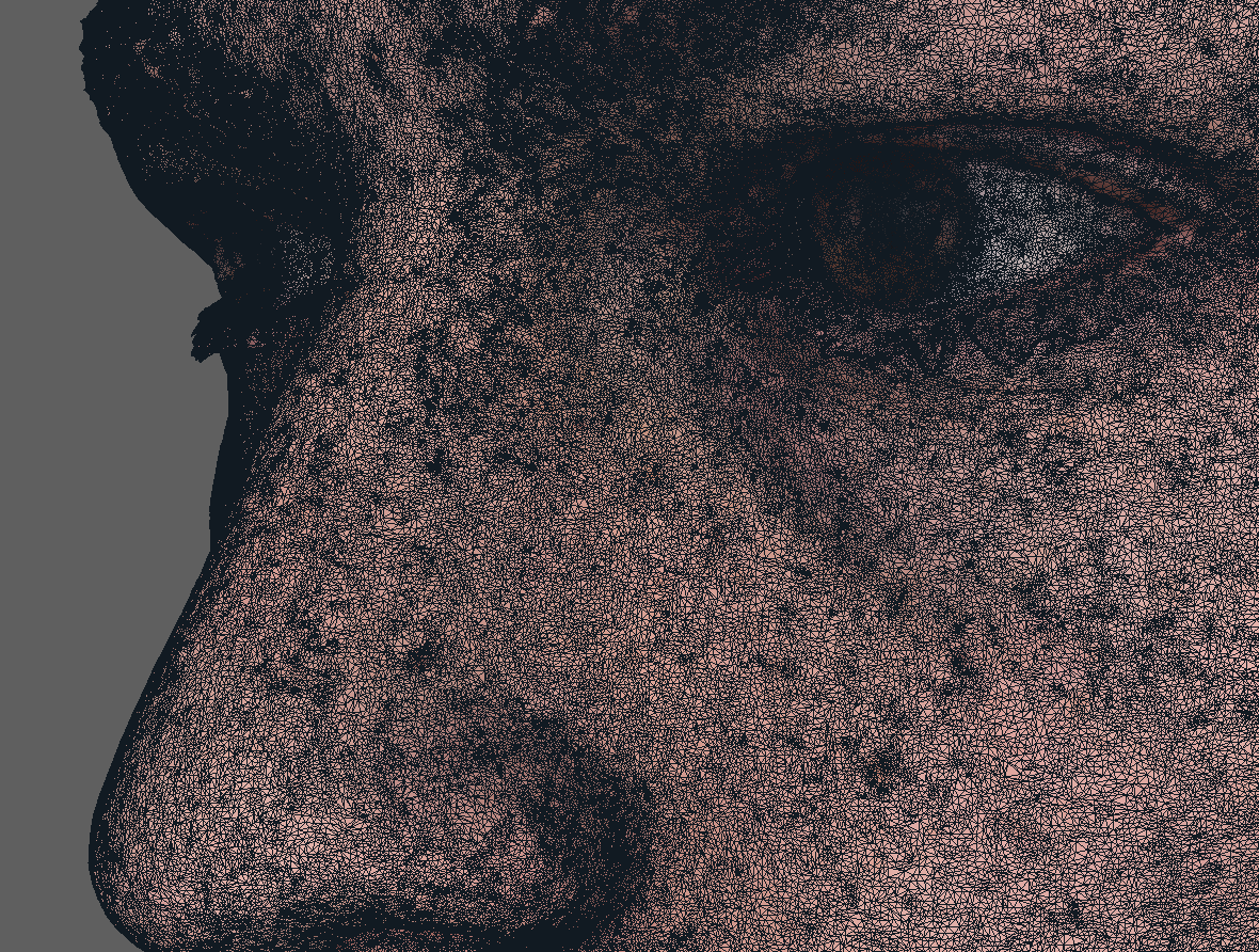
The Wrap 3.3 program will help us with this. It is widely used to process scanned models. With its help, we will project our future model of the head on the scans.
Part 2
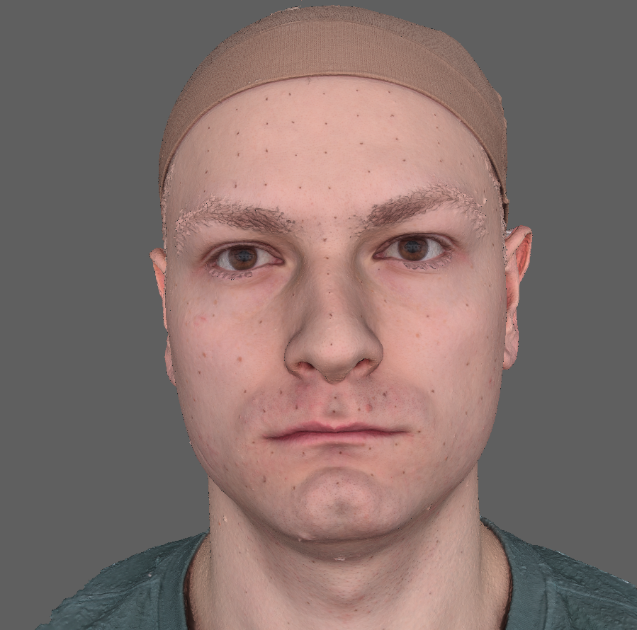
First you need to create the so-called base mesh. That is, a neutral facial expression that will underlie all emotions. Our neutral emotion scan looks like this:
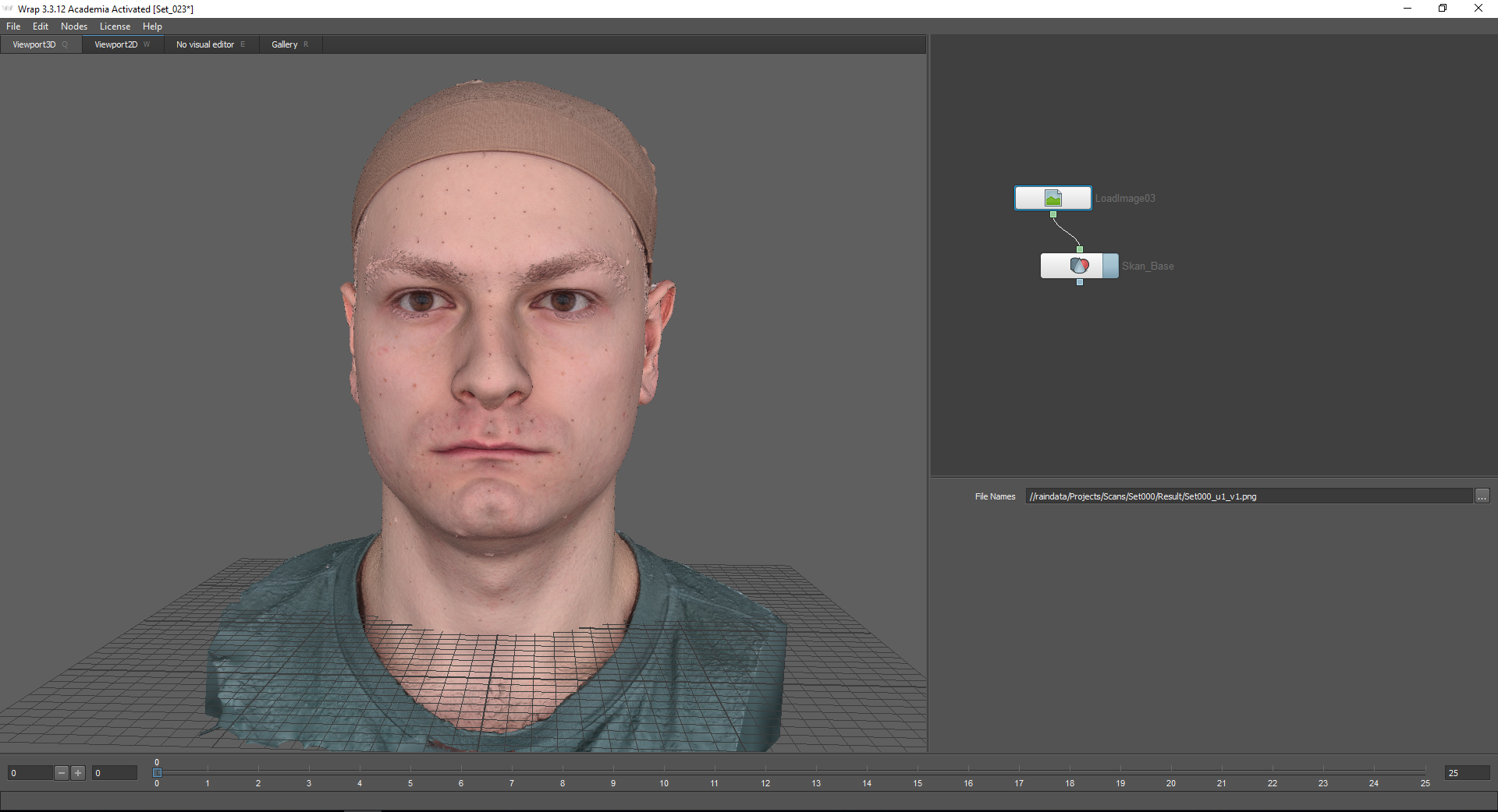
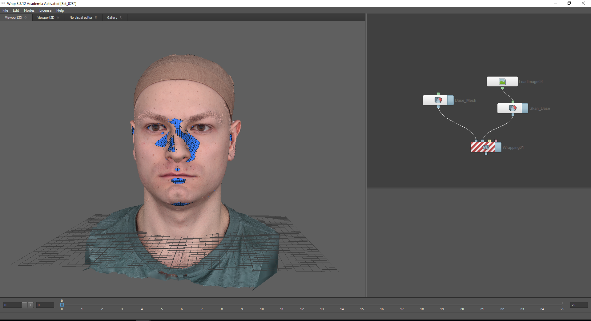
The Wrap 3.3 program has a node system, that is, all functions are presented in the form of nodes (nodes) that are connected to each other by a chain.
The selection of nodes is carried out using the Tab key. Using the LoadGeom and LoadImage nodes, a scan with a neutral emotion and its corresponding texture are loaded. To do this, specify the path in the File Names window. In the settings of the “LoadGeom” node, you can choose various modes of displaying the geometry (the wireframe function is disabled in the image below). Here you can also change the color of the geometry (does not work if the texture is connected), coordinates and scale.
Next, you need to load the base mesh, which will be projected onto this scan. You can find it on the “Gallery” tab. Here are many ready-made emotions. In this case, I choose Basemesh.

Basemesh should be roughly matched with a scan. To do this, you can use the coordinate axis.
To project the base mesh onto the scan, I use the Wrapping node. When you hover the mouse over the nodes of the node, a hint is displayed: the first node, Floating geometry — for the projected geometry, the second node, Fixet geometry — for the fixed object over which the geometry will be projected (in our case, this is a scan with a neutral emotion).
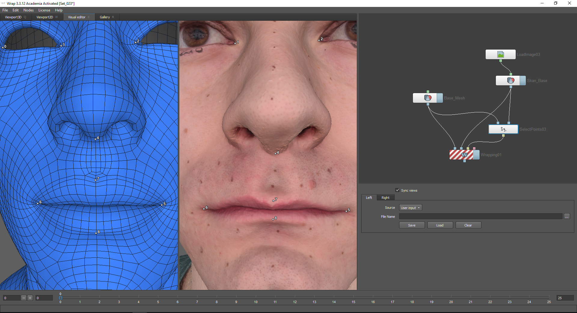
To start the calculation, it is necessary to mark the points on both models that will correspond to each other. For this, the Select points node is used, which is connected to the corresponding nodes of the models. After selecting this node, go to the Visual Editor tab. The included Sync views function allows you to synchronize cameras for the left and right windows.
If the projected model contains polygons that must remain in place, you must select them using the Select Polygons function. Otherwise, artifacts may occur associated with the internal details of the mesh.

To use the Select Polygons node, use the Visual Editor tab. Here you can select those polygons that Models from the gallery are divided into polygroups, this simplifies the task: they can be selected or deselected on the top panel.
I highlight the internal details of the throat, nostrils, extreme loupe of the eyelids and the lower part of the neck.

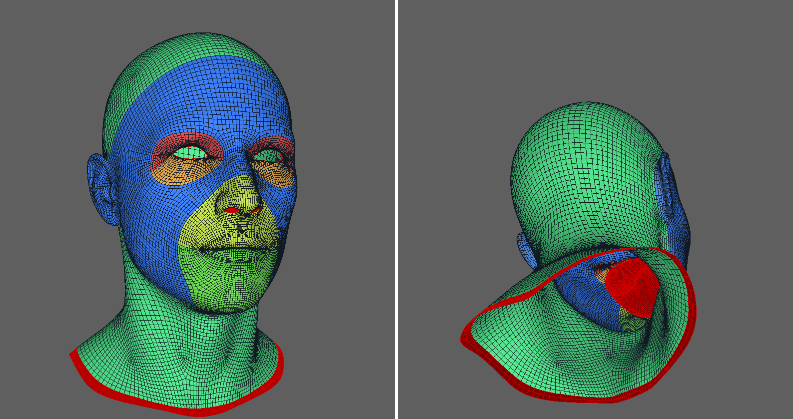
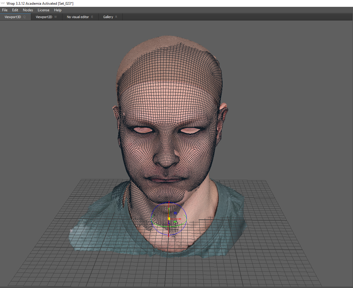
After that, the model will be projected correctly.
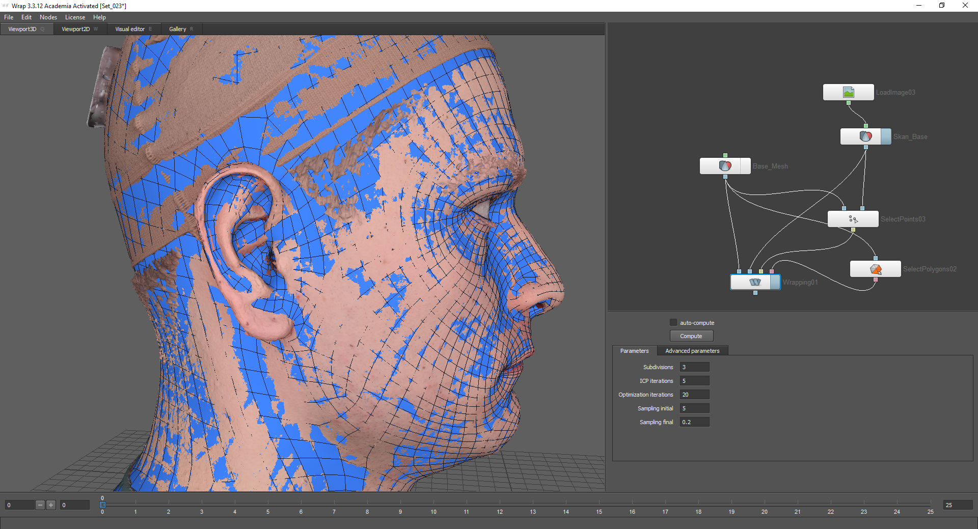
Also, for more granularity, you can use the Subdivide node. It connects to the base mesh and all the nodes below are connected to its lower node (Output).

Next, bake the texture from the scan to the base mesh. For this, the Transfer Texture node is used. The Source geometry node connects to the model with which the texture will bake. In our case, this is a scan. The Target geometry node is connected to the base mesh, but not to the LoadGeom node, but to the Wrapping node, since we will use the already modified, projected geometry.
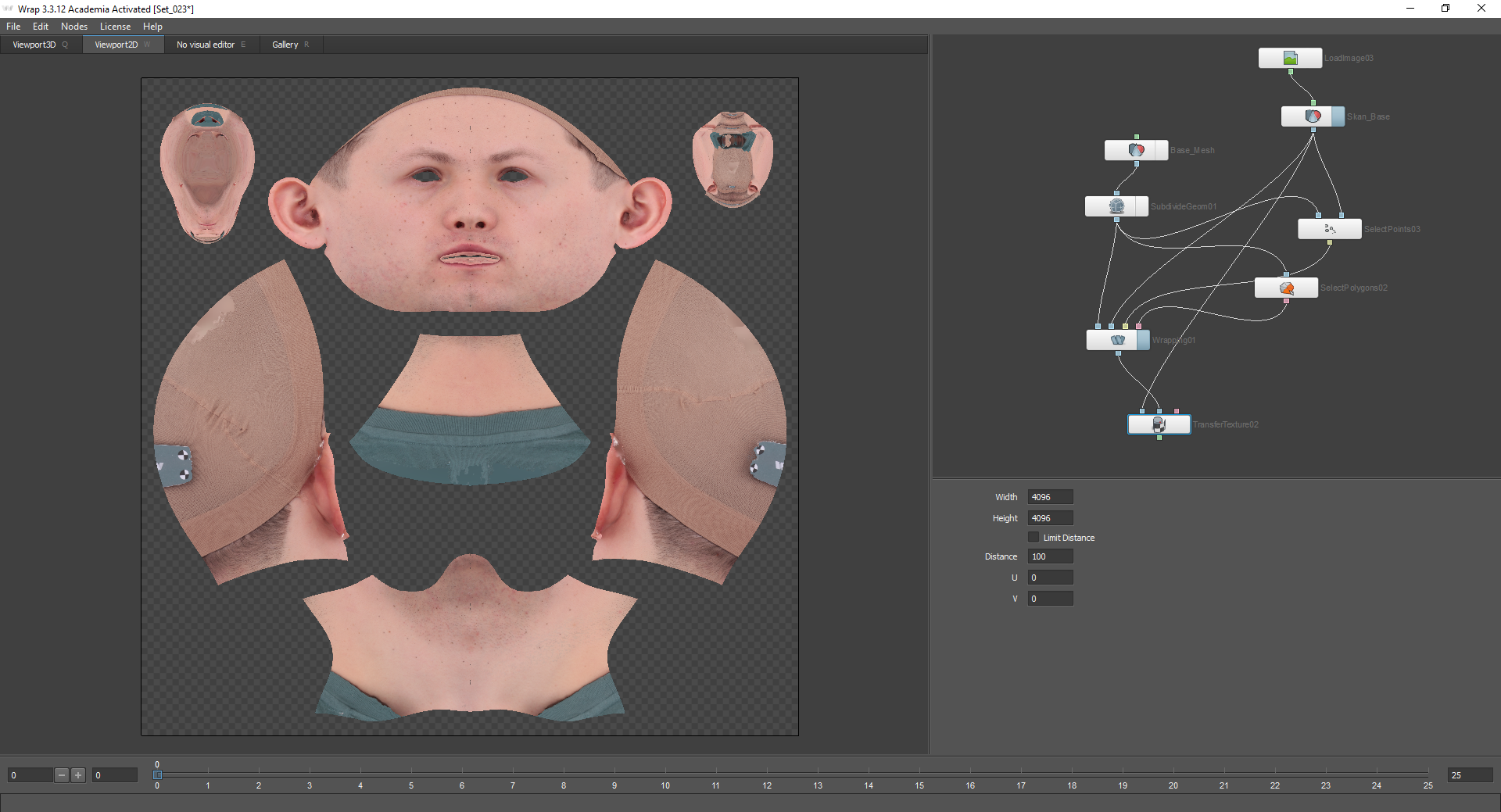
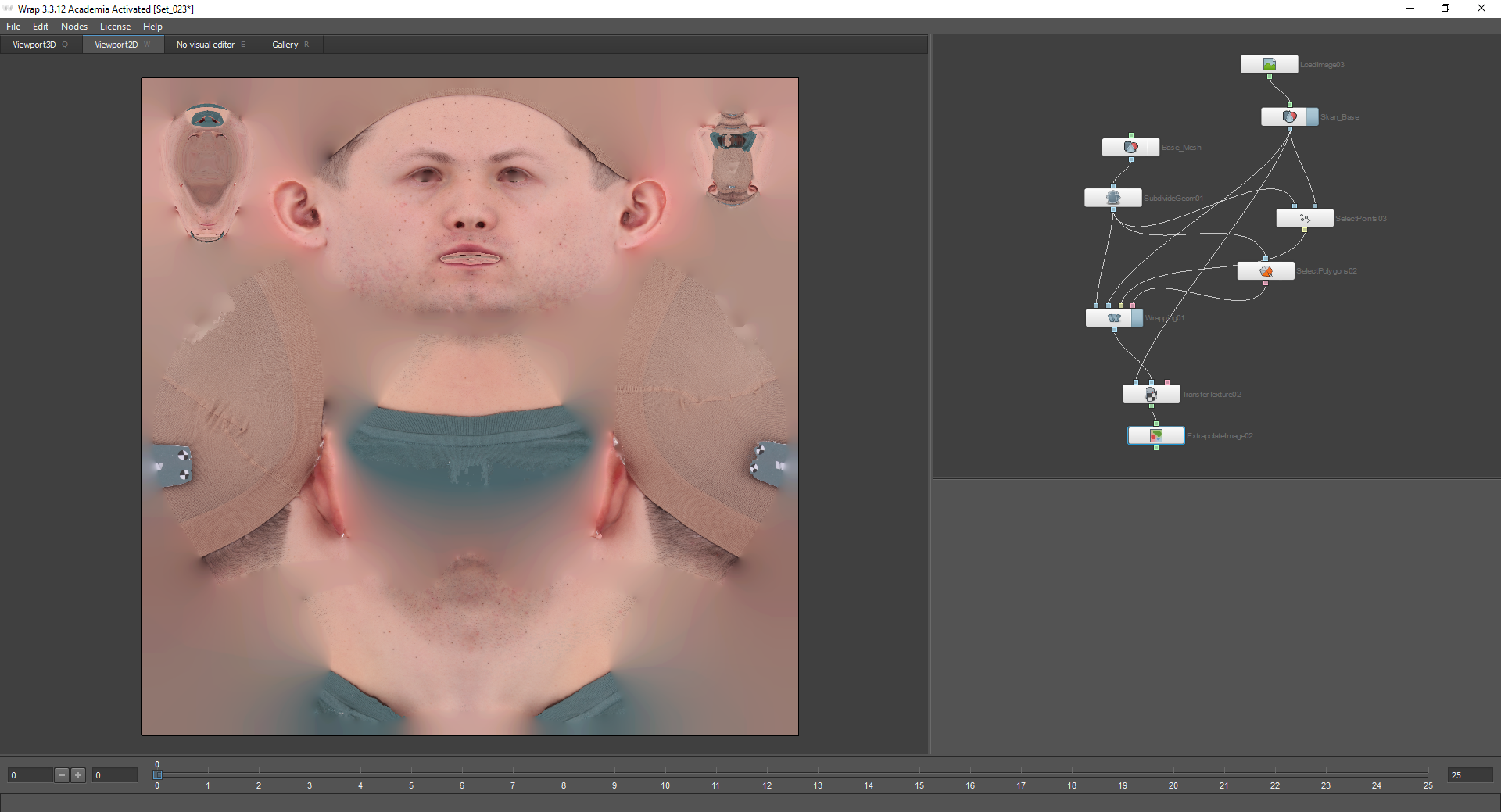
In the settings of this node, you can select the quality of the baked texture. After that, it is worth adding the Extrapolate Image node to fill in the transparent places, and save the resulting texture using the Save Image node and pressing the Compute current frame button. The geometry is saved in the same way using the Save Geom node.
Part 3
After we get a neutral emotion and texture for it, we can move on to obtaining geometry for other emotions. To do this, load the scan model and Basemesh with textures.

Next, you need to align Basemesh according to the scan. For starters, you can compare models approximately using coordinate axes.
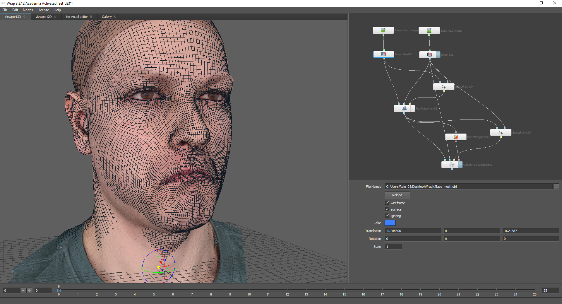
A node that allows you to more accurately align the models relative to each other - Rigid Alignment. The Floating geometry node connects the geometry that needs to be aligned. In the Fixed geometry node, respectively, there will be static geometry (in our case, this is a scan).
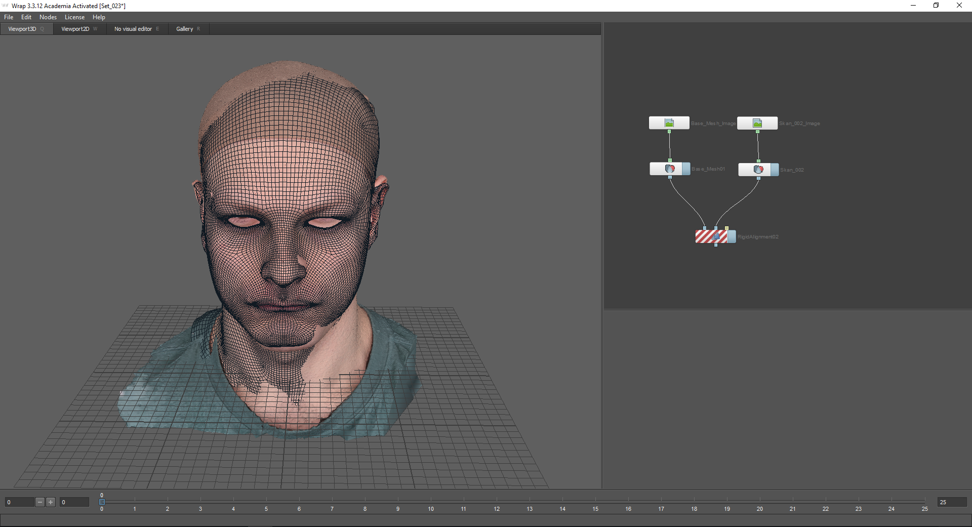
When using the Rigid Alignment node, you must use the Select Points node:

My model has control markers that simplify the task of selecting points. To align the models with respect to each other, points must be placed on those parts of the face that change slightly when depicting a particular emotion. In the case of this emotion, this is the forehead, upper part of the nose, neck, etc. Also, it is advisable to place points on all sides of the model (that is, for example, not only on the face, but also on the nape and ears).

As a result, we get models aligned relative to each other:

In the settings of the Rigid Alignment node, there is a “Match skale” function. It is used if models need to be scaled as well.
After that, you can start projecting the base mesh onto the scan. For this, we will use the Optical Flow Wrapping node. It allows you to align the geometry according to the texture of the scan. At the same time, the resulting texture of emotions will completely coincide with the texture of the base mesh, with the exception of wrinkles, wrinkles, and other changes. All irregularities of the skin and pores when using this method remain in place.

Before using the optical stream, as in the first case, the Select Polygons node is used:

Thus, the fixed parts of the head will remain in place.
You can also use the Select Points node. Here are the points on the moving parts of the face:

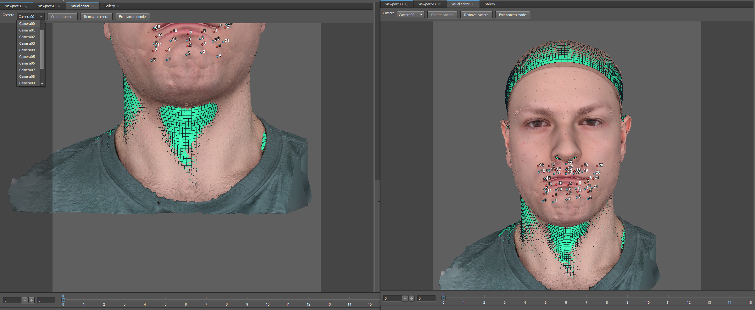
Next, go to the optical flow settings. Cameras that can be adjusted appeared in the Visual Editor window around the model.

At the top there is a drop-down menu with which you can go to the view from the camera. By default there are 13. It is necessary to set them so that the face completely fits into the frame.
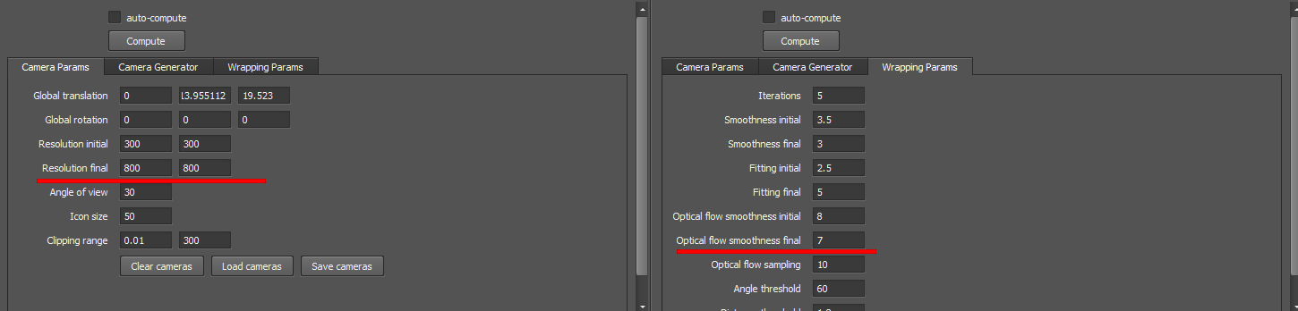
On the recommendation of the developers, I leave almost all the settings by default with the exception of the Resolution final and Optical flow smoothness final parameters:
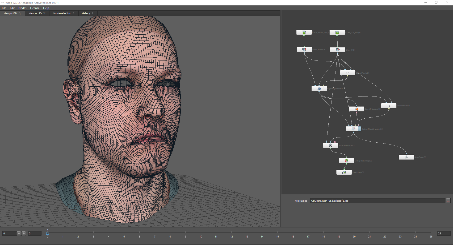
After that, you can click Compute and see the result:
After the mesh is projected onto the scan, bake the texture. this is done according to the same principle as in the first part of the article:

As a result, if you combine the resulting texture with the texture of the base mesh, some details will be added, but at the same time, the control points will coincide:

After that, the texture and the resulting geometry can be saved.
As a result, we got a mesh of a new emotion with a texture.
Part 4
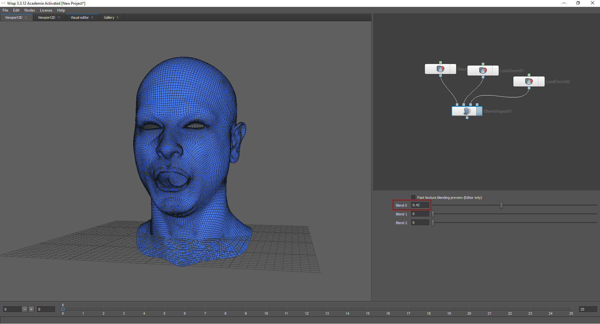
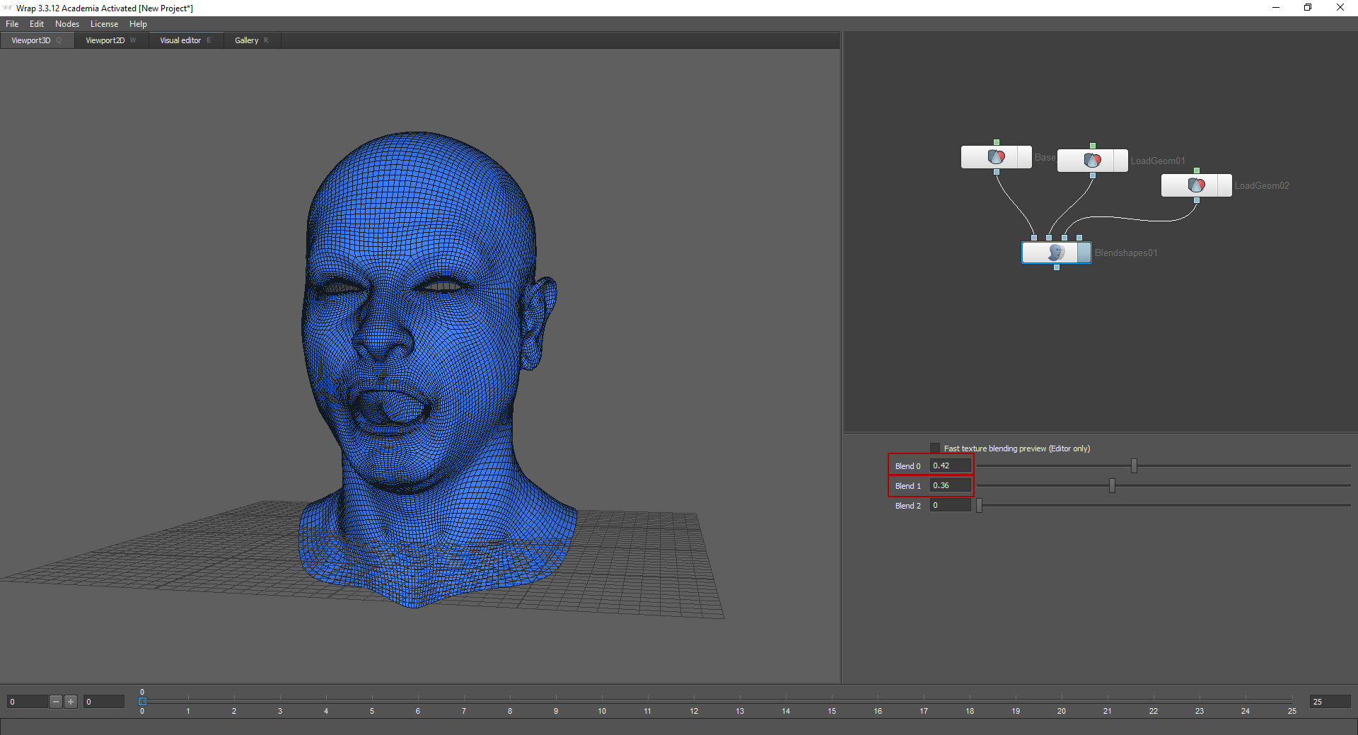
The Blend shapes method allows you to “mix emotions”. To do this, load already received meshes in the Blend shapes node.

I loaded neutral emotion into the first knot. Moving the sliders in the node settings, you can choose how strongly this or that emotion will be expressed. In order for this method to work, models must have the same topology.
Result
The above process is only a small part of a very voluminous work. After receiving LowPoly head models, it was necessary to create normal maps, rougness, subsurface, etc., as well as configure the shader (in our case, we configured the shader for the render and for the engine). Eyes, clothes and hair were also created separately. It is also worth noting that only three people performed this task. This was our first experience in creating a highly detailed character. We were satisfied with the result, but we will strive for more.
