Home CNC router as an alternative to a 3D printer, part four. General processing concepts
Having started writing about processing strategies, I realized that I was creating a “monkey set” - a step-by-step guide not even for dummies, but for idiots, you can repeat my steps, make your own patterns too, but understanding is not added. At one time, when I suddenly decided to become a milling machine operator, having the highest medical, MBA and 10 years of computer retail in the background, it was very difficult for me to wade through terminology and a completely new conceptual apparatus.
Of course, most CAM programs are equipped with good help, but nevertheless it was written by technologists for operators, and a person from the street can not always understand what “both in increments” is, why “cylinder security area” is needed, what type of approach to choose and what it is such a thing.
Below is my humble attempt to go over the basic concepts of milling with a brief transcript. I used Russian terminology from Delkamov’s textbooks, it may not coincide with other CAM programs, but I think here intuition and Google will save. Well, and as always, a drop of personal experience in processing plastics on hobby machines.
In fact, the spindle speed is an independent parameter, it depends on the tool and material. In the documentation for normal adult milling cutters there is a parameter “cutting speed” in m / min for different materials, this is the speed of the edge relative to the material.

To calculate the spindle speed, it is necessary to divide the recommended speed by the circumference. But there are 2 problems: firstly, we cut “home” materials such as plastics and wood, for which manufacturers do not specify cutting parameters, and secondly, we use hobby cutters, on which no modes are written at all. So we calculate the speed empirically: we draw a simple trajectory such as a groove, start the cutter into the material at a small (700-1000 mm / min) feed, and begin to slowly raise it from 6000. Start to melt / burn - reduce by a couple of steps. According to experience, for milling cutters with a diameter of 6 mm, the speed in viscous plastics (caprolon, PP, PE) is 6-8K, in hard (ABS, PS, PC) - 8-12k, in wood - 15-18K, in pollen - 10-20K . With a decrease in diameter, we increase the speed; on the finishing ones, we also increase.
The feed rate is also a derivative, but it’s even worse here - if on the one hand it depends on completely countable / documented “feed to tooth” numbers, then on the other it depends on the rigidity of the machine-tool-tool-part system (aka AIDS ) You can see the feed per tooth Sz or Fz in the documentation for the cutter, where it is described in mm / tooth (mm / t). When multiplied by the number of teeth of the cutter and the frequency of rotation, it will give the maximum theoretical feed rate.

But it’s difficult to measure the rigidity of the AIDS system, and it’s not justified, therefore, as always with home-made people, the feed parameter is selected from experience: we try different feeds, starting from 500 mm / min (we talk about plastics, yes) when we stop like sound (or break milling cutter, or the workpiece flies) - we reduce the speed. Do not forget that the feed for different cutters and different treatments will be different. The general rule is this: with a decrease in tooth extraction, we increase the speed, with an increase - we decrease. Although paradoxical effects sometimes occur in plastics, for example, the quality of vertical POM surfaces is higher at higher speeds. On my machines, when processing plastics, I most often use speeds from 1500 to 3000 mm / min, the surfaces are completely obtained.
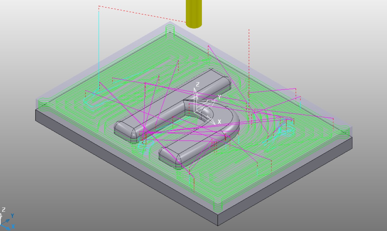
The security area, it is also OB, is a set of machine areas where CAM believes that it is guaranteed not to meet either workpieces or fasteners. Transitions are made through this area; in it, by default, it is allowed to go on accelerated feed. In ordinary 2.5D machining this is a plane - we fix the part so that it is clean and cloudless over the entire machining zone. Nevertheless, sometimes it makes sense to set OB differently, for example, if we mill only the sides of the workpiece, and fasten through the holes in the workpiece in the center. In addition, some milling cutters do not imply the possibility of vertical or even inclined incisions into the material and it is necessary to explain to CAM that the transitions and leads should only be on the side. In most normal CAMs, for this, the OB types are “block”, “cylinder”, or even “model”, which specify OBs, respectively.

Many materials and types of processing allow you not to bother with the concept of supply lines in general - PVC, PS, soft varieties of wood are cut in any direction by any cutter in the normal processing mode. The infeed was set up and drove off. However, the moment of entry into and exit from the material differs both for the milling cutter (uneven load on the plane, the work of the milling center when vertically cutting multi-cutters), and for the material (hanging burrs, knocking chips). Therefore, in CAM programs, it is usually provided the ability to set separate modes for approaches and taps.

On the one hand, everything is simple in the do-it-yourself camp: materials are soft, regimes and so gentle, so many generally disdain this parameter and put vertical inlets and outlets. On the other hand, a knocked-out sliver on a wooden bas-relief at the very end of many hours of processing or beaten by vibration of the cutter at the lowest of the 50 passes, the vertical wall is very unpleasant. Therefore, we use it reasonably: when roughing with normal (obviously large potential defect) allowances we work hard, set the minimum vertical leads, while finishing or fine work - we let them down depending on the operation along an arc or obliquely. But again, do not be foolish, long approaches and bends greatly increase the total processing time. On plastics during finishing, I put the carts obliquely during operations with horizontal and inclined surfaces and “horizontally along an arc” in operations with vertical walls. The length of the approach is selected individually, I put 2-3 diameters of the cutter or 10-15 thicknesses of the removal.
Actually, everything is relatively simple with heights. There is an absolute safe Z defined by OB. But imagine that you are working on the inscription at the bottom of the box with an offset with a very small step. A lot of small transitions, on each CAM, the cutter leads to OB, translates into a couple of millimeters and then painfully goes down. To avoid this, they came up with a relative safe Z - the height at which you can walk during finishing after the last sampling. It is only necessary to remember at the same time that if the selection is not made in real life, for example, the operator mixed up the order of the paths, the tool will try to switch between segments in the material, simultaneously turning the workpiece and breaking.
My personal parameters for small parts are absolute safe - 5-10 mm, relative - 2-5 mm.

Transition - a section of the trajectory between the working strokes of the cutter. As already mentioned, it can be carried out at an absolute or relative safe height, in the powermill the corresponding settings are called “safe” and “both in increments”. But sometimes, especially on the final or additional trajectories, it makes sense to organize the transition differently, so CAM programs provide options:
It’s even difficult to recommend something here. Probably for a beginner, the general rule is: the samples are “safe” or “both in increments,” the vertical walls are “Z steps,” 3D displacement or surfaces are “along the surface”.
A very simple, intuitive item.
Tolerance is a size that you care about and within which the CAM can be hung out as it wants. On the one hand, more tolerance - more freedom for CAM, smoother trajectory, fewer changes in direction, and so on. On the other hand, in rare cases, CAM can, for example, place an unloading approach of a sample in the middle of a vertical surface, and regardless of what you generally size of this area in the drum, the surface will become ugly. In our century of large amounts of memory and powerful computers that consider the trajectory, it’s better that CAM thinks a little longer and writes an extra couple of megabytes in the program than scratches its turnips on what to do with flaws. I put a tolerance in a hundred on plastics, it seems everyone is happy.
Oversize is originally a rough cut concept. At the CAM level, the oversize looks like building an equidistant (uniformly offset) from the original model. I already gave the general rule above - the size of the allowance must be obviously larger than the size of a potential processing defect, then even in case of trouble you can correct the flaw by further processing. In addition, the allowance can be used for other purposes, for example, to scale the model when fitting the matching grooves / bosses. On plastics in rough machining, I put an allowance of 0.3-0.7 mm, this is enough.
In general, somewhere like that. Now you can start the article on the construction of processing in CAM without being constantly distracted by thinking whether it’s clear enough that I am writing and not throwing footnotes in the article. If you forgot something or incomprehensibly put it - write comments, ask questions, I will try to answer.
If anyone missed, but interestingly, the previous articles in the series:
Home CNC router as an alternative to a 3D printer, part one - choosing a machine
Home CNC router as an alternative to a 3D printer, part two
Home CNC router as an alternative to a 3D printer, part three, software and G-code
Of course, most CAM programs are equipped with good help, but nevertheless it was written by technologists for operators, and a person from the street can not always understand what “both in increments” is, why “cylinder security area” is needed, what type of approach to choose and what it is such a thing.
Below is my humble attempt to go over the basic concepts of milling with a brief transcript. I used Russian terminology from Delkamov’s textbooks, it may not coincide with other CAM programs, but I think here intuition and Google will save. Well, and as always, a drop of personal experience in processing plastics on hobby machines.
Spindle speed
In fact, the spindle speed is an independent parameter, it depends on the tool and material. In the documentation for normal adult milling cutters there is a parameter “cutting speed” in m / min for different materials, this is the speed of the edge relative to the material.
To calculate the spindle speed, it is necessary to divide the recommended speed by the circumference. But there are 2 problems: firstly, we cut “home” materials such as plastics and wood, for which manufacturers do not specify cutting parameters, and secondly, we use hobby cutters, on which no modes are written at all. So we calculate the speed empirically: we draw a simple trajectory such as a groove, start the cutter into the material at a small (700-1000 mm / min) feed, and begin to slowly raise it from 6000. Start to melt / burn - reduce by a couple of steps. According to experience, for milling cutters with a diameter of 6 mm, the speed in viscous plastics (caprolon, PP, PE) is 6-8K, in hard (ABS, PS, PC) - 8-12k, in wood - 15-18K, in pollen - 10-20K . With a decrease in diameter, we increase the speed; on the finishing ones, we also increase.
Feed rate
The feed rate is also a derivative, but it’s even worse here - if on the one hand it depends on completely countable / documented “feed to tooth” numbers, then on the other it depends on the rigidity of the machine-tool-tool-part system (aka AIDS ) You can see the feed per tooth Sz or Fz in the documentation for the cutter, where it is described in mm / tooth (mm / t). When multiplied by the number of teeth of the cutter and the frequency of rotation, it will give the maximum theoretical feed rate.
But it’s difficult to measure the rigidity of the AIDS system, and it’s not justified, therefore, as always with home-made people, the feed parameter is selected from experience: we try different feeds, starting from 500 mm / min (we talk about plastics, yes) when we stop like sound (or break milling cutter, or the workpiece flies) - we reduce the speed. Do not forget that the feed for different cutters and different treatments will be different. The general rule is this: with a decrease in tooth extraction, we increase the speed, with an increase - we decrease. Although paradoxical effects sometimes occur in plastics, for example, the quality of vertical POM surfaces is higher at higher speeds. On my machines, when processing plastics, I most often use speeds from 1500 to 3000 mm / min, the surfaces are completely obtained.
Security area
The security area, it is also OB, is a set of machine areas where CAM believes that it is guaranteed not to meet either workpieces or fasteners. Transitions are made through this area; in it, by default, it is allowed to go on accelerated feed. In ordinary 2.5D machining this is a plane - we fix the part so that it is clean and cloudless over the entire machining zone. Nevertheless, sometimes it makes sense to set OB differently, for example, if we mill only the sides of the workpiece, and fasten through the holes in the workpiece in the center. In addition, some milling cutters do not imply the possibility of vertical or even inclined incisions into the material and it is necessary to explain to CAM that the transitions and leads should only be on the side. In most normal CAMs, for this, the OB types are “block”, “cylinder”, or even “model”, which specify OBs, respectively.
Approaches and bends
Many materials and types of processing allow you not to bother with the concept of supply lines in general - PVC, PS, soft varieties of wood are cut in any direction by any cutter in the normal processing mode. The infeed was set up and drove off. However, the moment of entry into and exit from the material differs both for the milling cutter (uneven load on the plane, the work of the milling center when vertically cutting multi-cutters), and for the material (hanging burrs, knocking chips). Therefore, in CAM programs, it is usually provided the ability to set separate modes for approaches and taps.
- Vertical Arc Approach
- Branch "directly"
- Transition "both in increments"
- Approach - moving on accelerated
- Lifting - moving on accelerated
On the one hand, everything is simple in the do-it-yourself camp: materials are soft, regimes and so gentle, so many generally disdain this parameter and put vertical inlets and outlets. On the other hand, a knocked-out sliver on a wooden bas-relief at the very end of many hours of processing or beaten by vibration of the cutter at the lowest of the 50 passes, the vertical wall is very unpleasant. Therefore, we use it reasonably: when roughing with normal (obviously large potential defect) allowances we work hard, set the minimum vertical leads, while finishing or fine work - we let them down depending on the operation along an arc or obliquely. But again, do not be foolish, long approaches and bends greatly increase the total processing time. On plastics during finishing, I put the carts obliquely during operations with horizontal and inclined surfaces and “horizontally along an arc” in operations with vertical walls. The length of the approach is selected individually, I put 2-3 diameters of the cutter or 10-15 thicknesses of the removal.
Heights
Actually, everything is relatively simple with heights. There is an absolute safe Z defined by OB. But imagine that you are working on the inscription at the bottom of the box with an offset with a very small step. A lot of small transitions, on each CAM, the cutter leads to OB, translates into a couple of millimeters and then painfully goes down. To avoid this, they came up with a relative safe Z - the height at which you can walk during finishing after the last sampling. It is only necessary to remember at the same time that if the selection is not made in real life, for example, the operator mixed up the order of the paths, the tool will try to switch between segments in the material, simultaneously turning the workpiece and breaking.
My personal parameters for small parts are absolute safe - 5-10 mm, relative - 2-5 mm.
Transitions and gaps
Transition - a section of the trajectory between the working strokes of the cutter. As already mentioned, it can be carried out at an absolute or relative safe height, in the powermill the corresponding settings are called “safe” and “both in increments”. But sometimes, especially on the final or additional trajectories, it makes sense to organize the transition differently, so CAM programs provide options:
- On the surface. Despite the fact that correctly configured approaches and outlets practically do not leave traces of tearing off the tool on the workpiece, sometimes, for example, if the transition distance is small, it makes sense to make the transition without tearing the cutters at all.
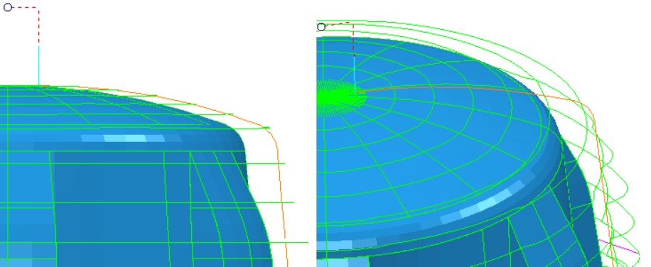
- Z step. The right choice for paths with constant closed machining of vertical walls, for example, constant Z
- Straight. A true hardcore option, CAM ignores everything and stupidly draws a line between the tap and the pull. And woe to the material encountered on the way, minus the operator’s salary, locking both the cutter and the workpiece. But respect and respect for the hero, who wisely used the tool and reduced the time of switching to hours (not a joke, it was).
It’s even difficult to recommend something here. Probably for a beginner, the general rule is: the samples are “safe” or “both in increments,” the vertical walls are “Z steps,” 3D displacement or surfaces are “along the surface”.
Allowances and tolerances
A very simple, intuitive item.
Tolerance is a size that you care about and within which the CAM can be hung out as it wants. On the one hand, more tolerance - more freedom for CAM, smoother trajectory, fewer changes in direction, and so on. On the other hand, in rare cases, CAM can, for example, place an unloading approach of a sample in the middle of a vertical surface, and regardless of what you generally size of this area in the drum, the surface will become ugly. In our century of large amounts of memory and powerful computers that consider the trajectory, it’s better that CAM thinks a little longer and writes an extra couple of megabytes in the program than scratches its turnips on what to do with flaws. I put a tolerance in a hundred on plastics, it seems everyone is happy.
Oversize is originally a rough cut concept. At the CAM level, the oversize looks like building an equidistant (uniformly offset) from the original model. I already gave the general rule above - the size of the allowance must be obviously larger than the size of a potential processing defect, then even in case of trouble you can correct the flaw by further processing. In addition, the allowance can be used for other purposes, for example, to scale the model when fitting the matching grooves / bosses. On plastics in rough machining, I put an allowance of 0.3-0.7 mm, this is enough.
In general, somewhere like that. Now you can start the article on the construction of processing in CAM without being constantly distracted by thinking whether it’s clear enough that I am writing and not throwing footnotes in the article. If you forgot something or incomprehensibly put it - write comments, ask questions, I will try to answer.
If anyone missed, but interestingly, the previous articles in the series:
Home CNC router as an alternative to a 3D printer, part one - choosing a machine
Home CNC router as an alternative to a 3D printer, part two
Home CNC router as an alternative to a 3D printer, part three, software and G-code
All Articles