Industrial controller. Data collection system. ACS
Good day, Habr!
Development of an industrial controller with a display for collecting and analyzing data, as well as for managing loads grouped. Who cares what came of it, please, under cat.
The topic of industrial controllers has long been developing for use in automated control systems (ACS). When I see the next controller from Siemens, ViewPAC or any other manufacturer, I see only a large tablet (I write about this form factor, that is, not rack-mount options) with specialized software inside, but this is only at first glance. In fact, most often, only the appearance from the side of the display is similar, but the rear panel has interface connectors, compartments for connecting expansion modules, sensors, external storage media, etc. There are universal industrial controllers and highly specialized, that is, designed to perform a set of tasks, most often of the same type.
It is such a (highly specialized) controller that we developed. For starters, a few words about implementation. Globally, the device is divided into two parts. The first is the module on the iMX6D, which we developed just for the implementation of such tasks, the second is the STM32F103RBT7 microcontroller. As I wrote earlier (in previous articles), it is the block (modular) system that allows you to quickly implement complex projects. In such a system, most of the hardware and software complex has already been debugged, and it remains only to coordinate it with other modules and modify it for the end customer.
iMX6D
A full-fledged processor module (two cores at 1 GHz), which deals with a number of tasks for interacting with the user:
And this is not a complete list of what the module does.
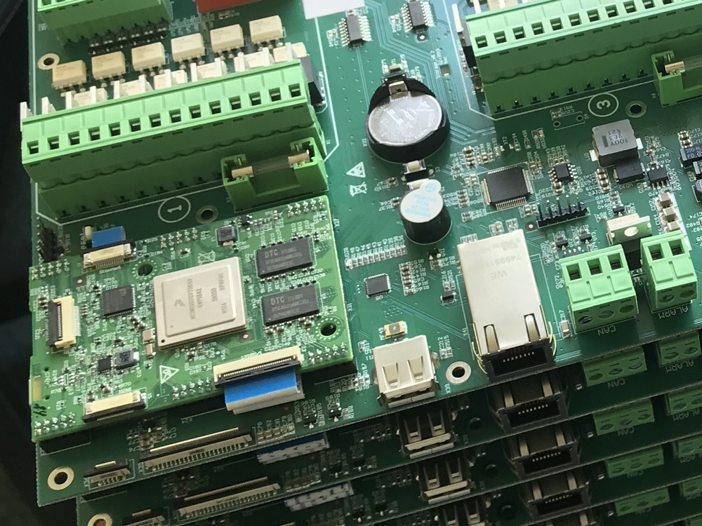
Fig. 1. Processor module
The web-based interface almost completely repeats the picture from the display, which makes it easy for users to navigate and quickly change settings. The implementation, as in previous projects, is based on the “11-parts” engine. Since the microcontroller performs the lion's share of the tasks, it became necessary to update its firmware (as well as the main one) via the web. This task was especially acute, as the customer planned to update devices to expand the functionality. The processor module is connected to the microcontroller via UART (the latter is also flashed through it).
STM32
The microcontroller in this project is very important. Firstly, its use made it possible to parallelize tasks for programmers and distinguish two main areas:
Secondly, a modular system is more convenient for debugging, testing and expanding functionality.
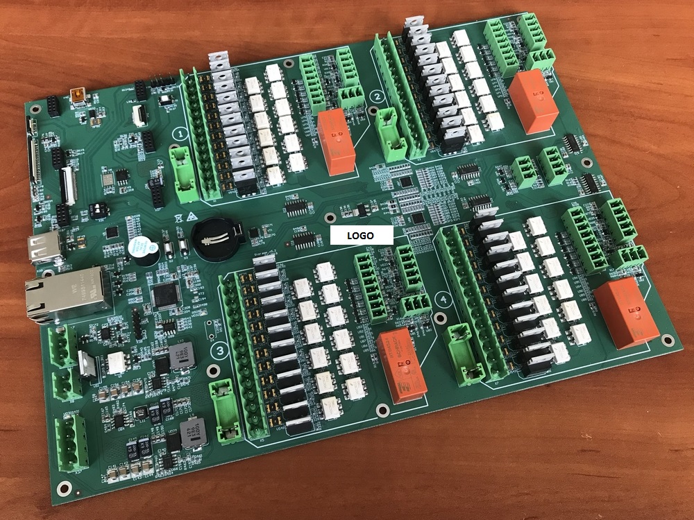
This industrial controller (hereinafter referred to as PC) allows servicing four independent rooms (groups) with a large number of sensors of actuating elements.
Specifically for this project for each group are available:
Also several street sensors:
In total, it turns out that the microcontroller collects data from 48 sensors and controls 48 actuators. All temperature sensors are analog. Humidity and CO2 sensors have a 4-20mA current interface.
Now a little circuitry. For switching sensors, it was decided to use the HCF4051 analog multiplexers (they have a switching delay, but this was not critical for our task). It is this series that has already been discontinued, its difference, for example, from the CD4051 only in switching speed (well, in the manufacturer). There are six such multiplexers in the controller. Switching of all multiplexers occurs simultaneously (by the same legs of the microcontroller), which significantly reduces the resources and read time. On the microcontroller, respectively, six ADC channels are involved.
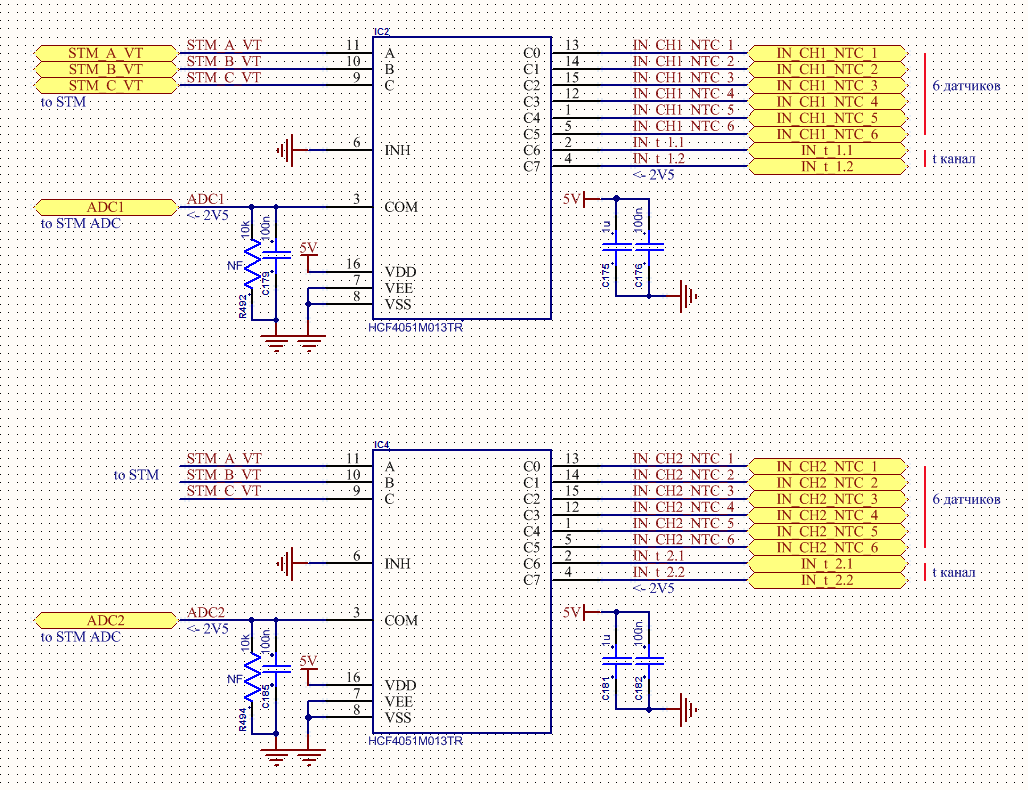
Fig. 2. Multiplexer switching circuit
For each temperature sensor, a separate reference voltage source TL431 (in the SOT-23 package) is used, thus, with a short circuit on one of the sensors, the others continue to work as before. To supply power to all oporniku used LM1117 3.3V. The board is powered from an external DC24V source, therefore, for the secondary power supply, two identical DC / DC TPS54560DDAR are used (formation of 12V and 5V), since I use them not in the first project. 3.3V is obtained from 5V using ST1S10.
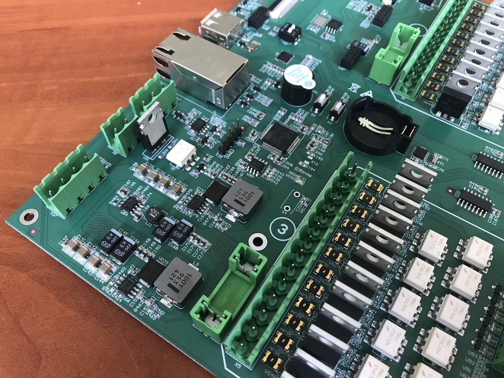
Fig. 3. Location of feeders on the board
To control external loads, relays are usually used, triggered by the supply of 24V alternating current. Therefore, AC24V is supplied to each group, which are switched by BT138-600 triacs via optocoupler isolation. The scheme is presented below. Everything works stably.
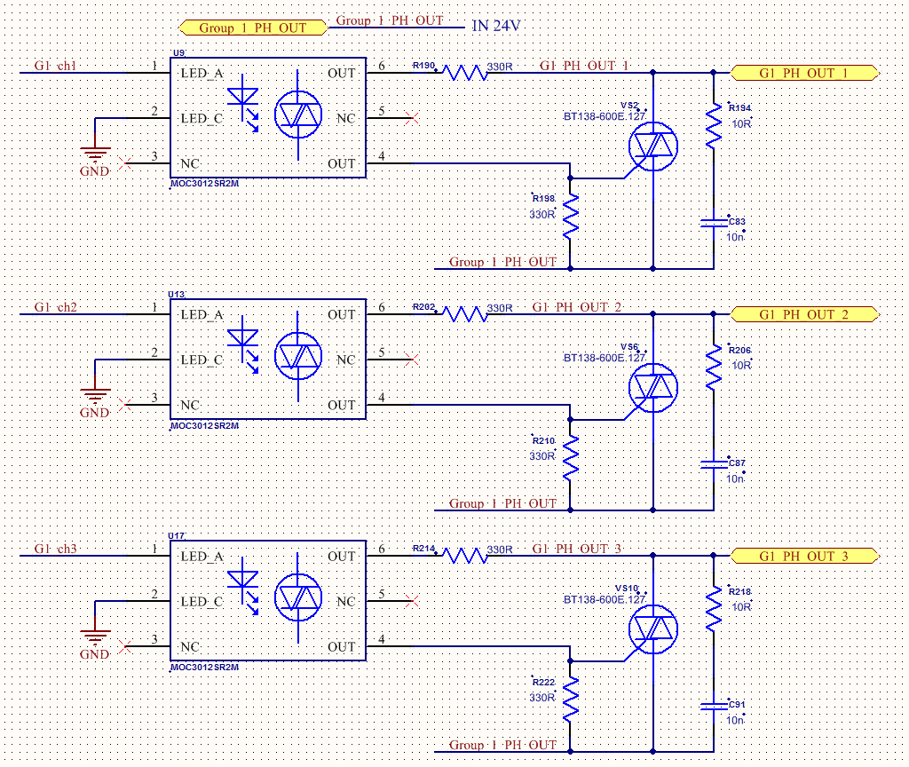
Fig. 4. Triac control circuit
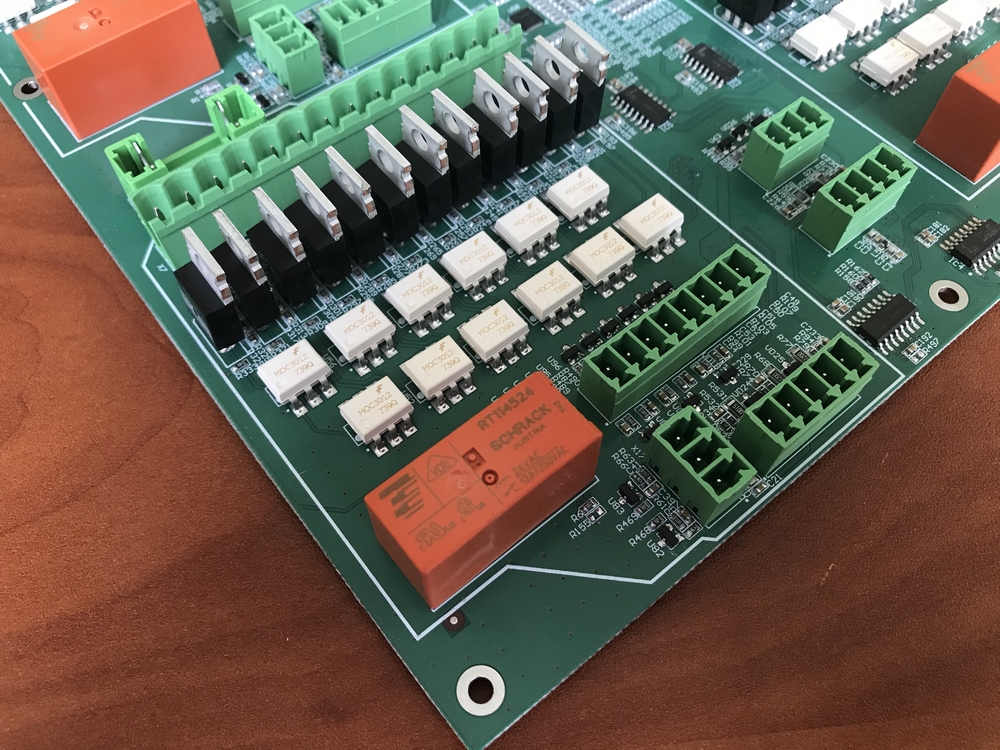
Fig. 5. Group of sensor connectors and control signals on the board
Management programs are stored on a separate EEPROM connected to the microcontroller. The initial parameters during hot start and the last state of the entire system are stored there (so that the program can continue to be executed).
It is clear that the microcontroller does not have enough GPIO to control such a number of optocouplers (and it’s not humane to drag as many wires across the board), therefore, TCA6424ARGJR port expanders are used, one for two groups and one system (processing several input signals, processing system buttons, LED indicators, etc.).
The relay, which is clearly visible in Fig. 5. (one for each group), is used to determine the presence of the input voltage AC24V and the health of the fuse for each group. When triggered, it sends a signal to the microcontroller, which, in turn, notifies of a malfunction.
Time is synchronized using the NTP protocol, but there is also an RTC PCF8523 chip (also used repeatedly) to calculate the time in the absence of a supply voltage.
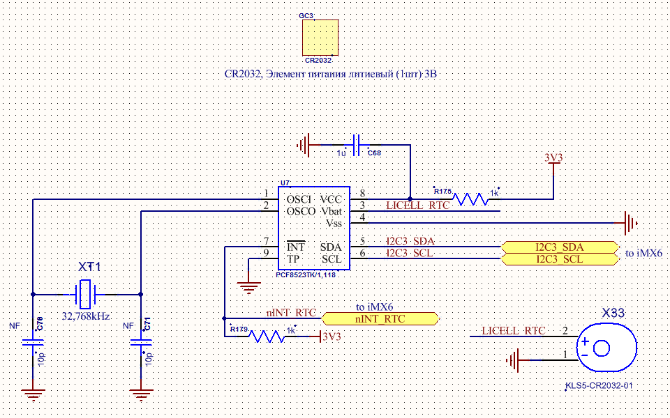
Fig. 6. RTC circuit
Display
PC control is carried out quickly using a touchscreen and remotely via the web. As I said, the browser interface (this functionality is still being finalized) repeats the screen. At the moment, an application is written in Qt, which communicates with a PC directly via mqtt and is as close to reality as possible. In the web, at the moment, there are general device settings, organization of access and software updates.
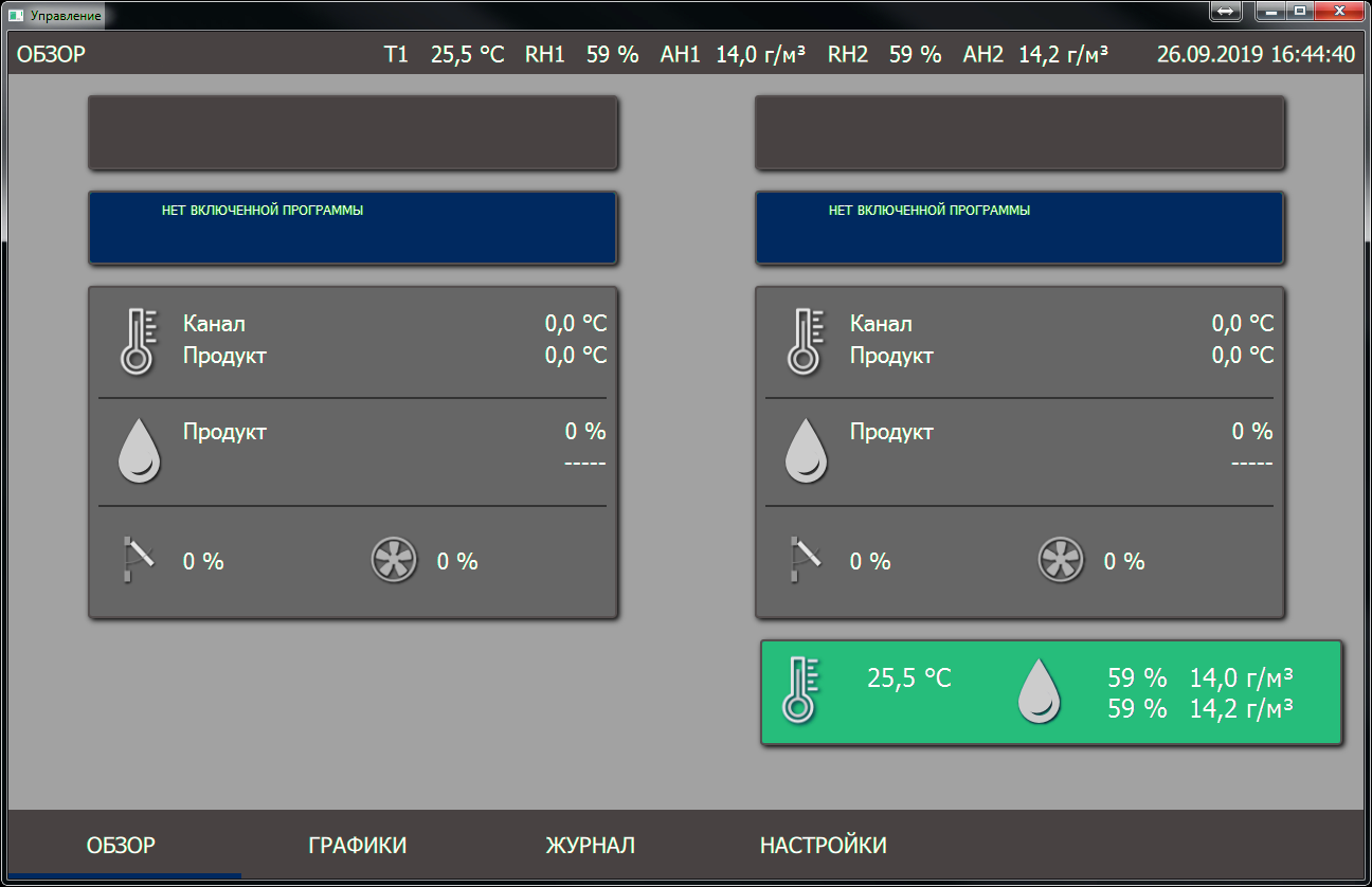
Fig. 7. Display data in the application on Qt
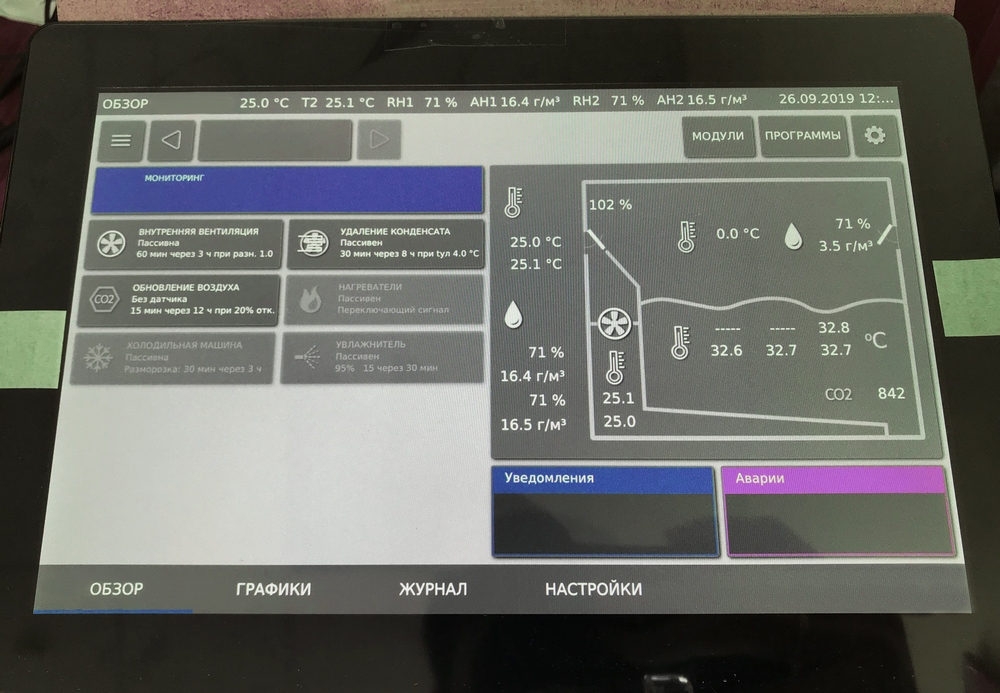
Fig. 8. Display data
These types of controllers allow you to build complete ACS for industrial complexes. Functionality and a set of sensors, as a rule, are different and correspond to the required tasks, but the purpose is the same - monitoring and / or control. For large systems, you can increase the number of controllers united by one task. The controller may not contain a display, but can be controlled via a network (Ethernet).
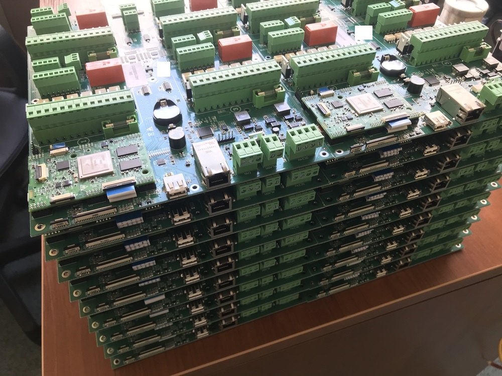
Fig. 9. Small party
Thank you and see you soon!
Development of an industrial controller with a display for collecting and analyzing data, as well as for managing loads grouped. Who cares what came of it, please, under cat.
The topic of industrial controllers has long been developing for use in automated control systems (ACS). When I see the next controller from Siemens, ViewPAC or any other manufacturer, I see only a large tablet (I write about this form factor, that is, not rack-mount options) with specialized software inside, but this is only at first glance. In fact, most often, only the appearance from the side of the display is similar, but the rear panel has interface connectors, compartments for connecting expansion modules, sensors, external storage media, etc. There are universal industrial controllers and highly specialized, that is, designed to perform a set of tasks, most often of the same type.
It is such a (highly specialized) controller that we developed. For starters, a few words about implementation. Globally, the device is divided into two parts. The first is the module on the iMX6D, which we developed just for the implementation of such tasks, the second is the STM32F103RBT7 microcontroller. As I wrote earlier (in previous articles), it is the block (modular) system that allows you to quickly implement complex projects. In such a system, most of the hardware and software complex has already been debugged, and it remains only to coordinate it with other modules and modify it for the end customer.
iMX6D
A full-fledged processor module (two cores at 1 GHz), which deals with a number of tasks for interacting with the user:
- data output on the display / touchscreen processing;
- Ethernet 10/100/1000;
- time synchronization;
- storage of event logs;
- web-interface + update;
- storage of profile data;
- complex calculations for the microcontroller.
And this is not a complete list of what the module does.
Fig. 1. Processor module
The web-based interface almost completely repeats the picture from the display, which makes it easy for users to navigate and quickly change settings. The implementation, as in previous projects, is based on the “11-parts” engine. Since the microcontroller performs the lion's share of the tasks, it became necessary to update its firmware (as well as the main one) via the web. This task was especially acute, as the customer planned to update devices to expand the functionality. The processor module is connected to the microcontroller via UART (the latter is also flashed through it).
STM32
The microcontroller in this project is very important. Firstly, its use made it possible to parallelize tasks for programmers and distinguish two main areas:
- User interaction.
- Data collection, processing and management.
Secondly, a modular system is more convenient for debugging, testing and expanding functionality.
This industrial controller (hereinafter referred to as PC) allows servicing four independent rooms (groups) with a large number of sensors of actuating elements.
Specifically for this project for each group are available:
- 6 temperature sensors combined into a single entity to determine the average;
- 2 independent temperature sensors;
- 2 humidity sensors;
- 1 CO2 sensor;
- 12 control channels for external actuators.
Also several street sensors:
- 2 independent temperature sensors;
- 2 humidity sensors.
In total, it turns out that the microcontroller collects data from 48 sensors and controls 48 actuators. All temperature sensors are analog. Humidity and CO2 sensors have a 4-20mA current interface.
Now a little circuitry. For switching sensors, it was decided to use the HCF4051 analog multiplexers (they have a switching delay, but this was not critical for our task). It is this series that has already been discontinued, its difference, for example, from the CD4051 only in switching speed (well, in the manufacturer). There are six such multiplexers in the controller. Switching of all multiplexers occurs simultaneously (by the same legs of the microcontroller), which significantly reduces the resources and read time. On the microcontroller, respectively, six ADC channels are involved.
Fig. 2. Multiplexer switching circuit
For each temperature sensor, a separate reference voltage source TL431 (in the SOT-23 package) is used, thus, with a short circuit on one of the sensors, the others continue to work as before. To supply power to all oporniku used LM1117 3.3V. The board is powered from an external DC24V source, therefore, for the secondary power supply, two identical DC / DC TPS54560DDAR are used (formation of 12V and 5V), since I use them not in the first project. 3.3V is obtained from 5V using ST1S10.
Fig. 3. Location of feeders on the board
To control external loads, relays are usually used, triggered by the supply of 24V alternating current. Therefore, AC24V is supplied to each group, which are switched by BT138-600 triacs via optocoupler isolation. The scheme is presented below. Everything works stably.
Fig. 4. Triac control circuit
Fig. 5. Group of sensor connectors and control signals on the board
Management programs are stored on a separate EEPROM connected to the microcontroller. The initial parameters during hot start and the last state of the entire system are stored there (so that the program can continue to be executed).
It is clear that the microcontroller does not have enough GPIO to control such a number of optocouplers (and it’s not humane to drag as many wires across the board), therefore, TCA6424ARGJR port expanders are used, one for two groups and one system (processing several input signals, processing system buttons, LED indicators, etc.).
The relay, which is clearly visible in Fig. 5. (one for each group), is used to determine the presence of the input voltage AC24V and the health of the fuse for each group. When triggered, it sends a signal to the microcontroller, which, in turn, notifies of a malfunction.
Time is synchronized using the NTP protocol, but there is also an RTC PCF8523 chip (also used repeatedly) to calculate the time in the absence of a supply voltage.
Fig. 6. RTC circuit
Display
PC control is carried out quickly using a touchscreen and remotely via the web. As I said, the browser interface (this functionality is still being finalized) repeats the screen. At the moment, an application is written in Qt, which communicates with a PC directly via mqtt and is as close to reality as possible. In the web, at the moment, there are general device settings, organization of access and software updates.
Fig. 7. Display data in the application on Qt
Fig. 8. Display data
These types of controllers allow you to build complete ACS for industrial complexes. Functionality and a set of sensors, as a rule, are different and correspond to the required tasks, but the purpose is the same - monitoring and / or control. For large systems, you can increase the number of controllers united by one task. The controller may not contain a display, but can be controlled via a network (Ethernet).
Fig. 9. Small party
Thank you and see you soon!
All Articles