Android for the radio engineer (and not only)
From the very moment when I purchased my first smartphone running Android, I was looking for applications for this OS that would help me do simple work calculations “on the palm”. One of these applications will be discussed.
The computational power of modern smartphones is simply amazing. And I really wanted to use these computing resources to perform work calculations. Let simple, but necessarily useful and necessary.
For a long time I surfed the vastness of Google Play and other resources in search of a tool that would satisfy my requests. And at some point in time, the search was successful - I found the RF & Microwave Toolbox . It should be noted that the creator of this wonderful application is the developer of microwave devices (" rf and microwave circuit design "), therefore, the application implements really useful and popular functions. The developer himself says the following about his application:
“This is the best and most advanced High frequency electronics toolbox for Microwave designers, RF professionals, EMC technicians, radio-amateur, students, astronomer and electronic hobbyists.”
Those. The audience is quite wide and it is not only radio engineers, but also radio amateurs, technical specialists in the field of EMC, students, astronomers and those people for whom radio electronics is a hobby.
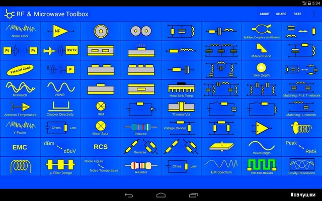
The application interface looks rather concise, representing a tile, each “brick” of which leads to a separate “calculator” (calculation or tool - “tool”). On the screen of my smartphone fits three pages with a set of "calculators":
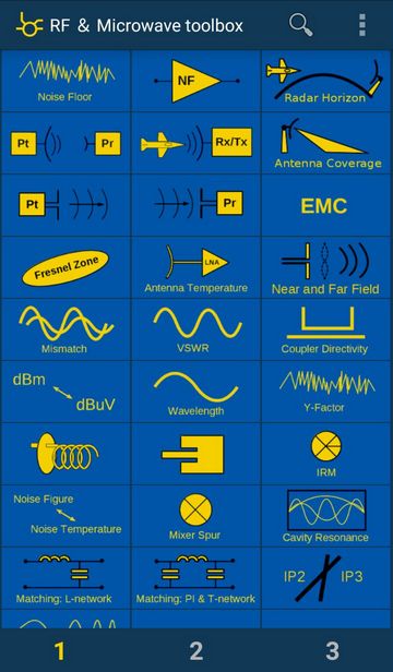
Page 1
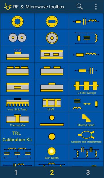
page 2
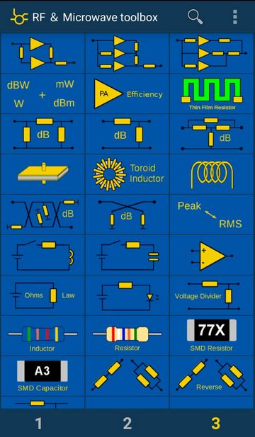
page 3
On each page there are about 30 different instruments, on three - almost 90! Therefore, I will not talk about each instrument separately, but only about those that I often use myself. You can learn the rest yourself.
Let's see what is there ...
1. Mismatch Error Limits - the spread associated with the mismatch error.
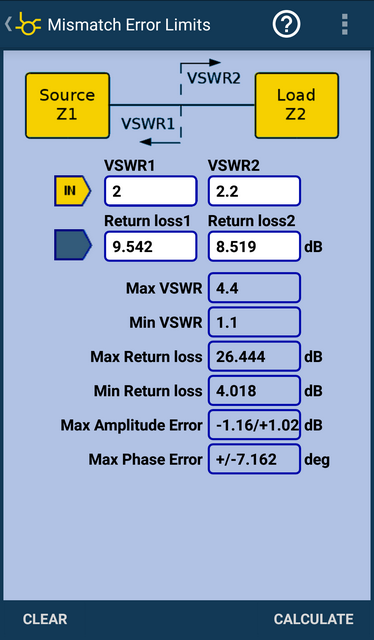
The VSWR of the source and load in the specified section is introduced and the maximum and minimum VSWR in the line are calculated, as well as a number of associated characteristics (return losses, amplitude and phase errors).
2. Reflectometer - reflectometer (on the VSWR icon).
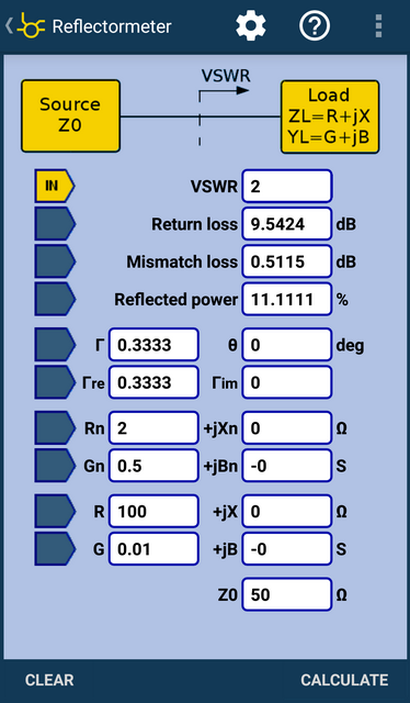
The input field can be selected in the left column. In the example in the picture, the VSWR field (= 2) was selected and the calculation was performed:
Below are the values of the reflection coefficient (G is the module and phase, the real and imaginary part), load and conductivity.
3. Power and Voltage Converter - conversion from units of power to units of voltage and current, as well as vice versa.
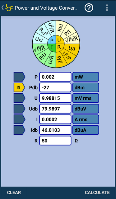
In the presented image, a conversion from logarithmic power units (dBm) was performed. It must be remembered that by default, the calculation is done for a resistance of 50 ohms.
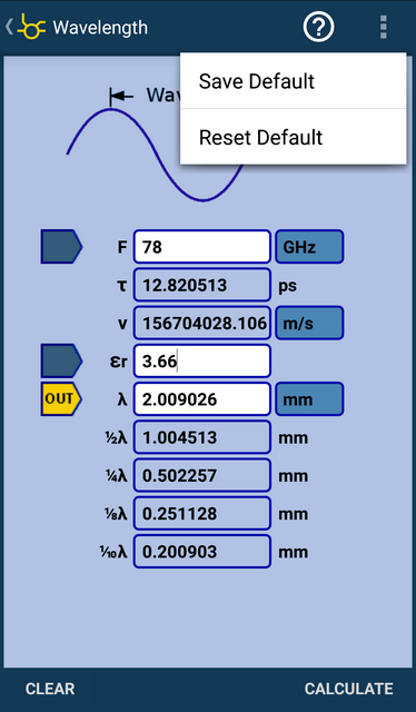
4. Wavelength - calculation of the wavelength.
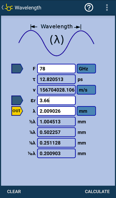
It is performed for the given frequency and medium parameters (determined by the value of the relative dielectric constant εr). The output is the wavelength and its fraction (1/2, 1/4, 1/8, 1/10), the speed of propagation of electromagnetic waves in the medium (v) and the duration of the oscillation period (τ).
I forgot to say that each calculation has its own help (question mark in the upper right corner of the screen), where you can see by what formulas the calculation is made, how to use the “calculator” correctly.
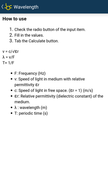
If necessary, you can save the calculation as a template so that you can quickly return to it later.
5. Patch Antenna - a planar “patch” antenna (meaning a microstrip rectangular patch antenna with an “inset feed” power scheme ).
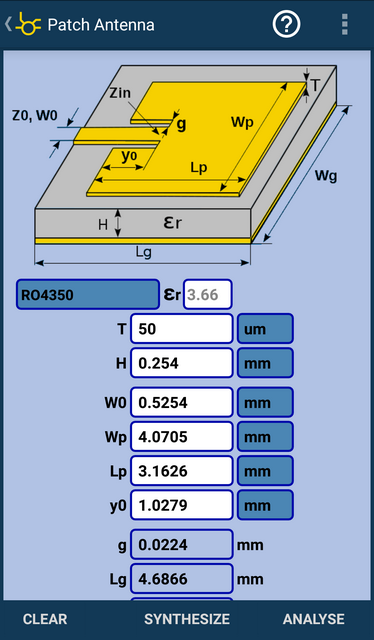
Not otherwise, this calculation appeared for those involved in the development of planar antenna arrays for subscriber terminals of 5G networks :) Although ... a rectangular patch antenna is used in many antenna solutions - from communication and data transmission systems of various frequency ranges to car radars (24 and 77 GHz). Both in a single form, and in the form of arrays (lattices).
In addition to calculating the patch antenna, there is also a guide to the most popular materials for printed circuit boards (including Rogers ).
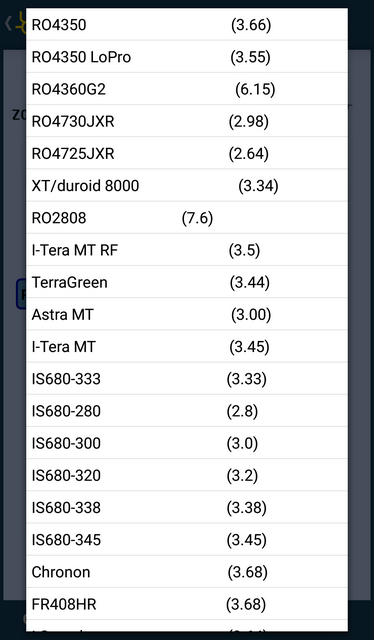
This is very convenient because no need to remember this data or look for it somewhere. Just poked into the list and chose the most suitable material.
Of course, this tool does not count the radiation pattern (NAM). But if you are interested in what type of antenna has such an antenna, you can look, for example, here .
6. IP3 - calculation of the “3rd order intersection point” (or determination of the level of intermodulation distortions of the 3rd order).
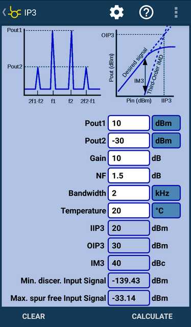
Honestly, here I am always confused, because the practical value of the IP3 value eludes me all the time. It’s easier for me to operate with the level of 3rd order intermodulation distortion (IMD 3). But in foreign technical literature, as a rule, IP3 is given. And therefore, such a tool for me is just a find, because on the “palm”, without departing from the cash register, so to speak, you can immediately estimate the 3rd order IMD level at the output of the active ( non-linear ) circuit. For the RF path, this is an important indicator, which is discussed in the terms of reference (TOR).
7. Radar Cross Section ( RCS ) - effective scattering surface (or area) ( EPR ).
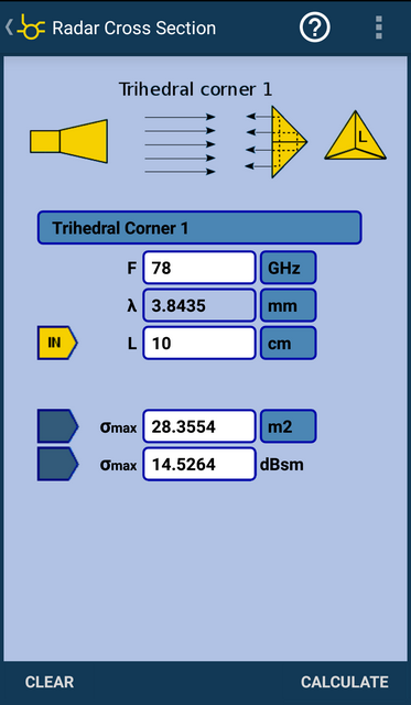
The picture above shows an example of EPR calculation for a tetrahedral reflective angle with side length L. Similar angles are used to test prototype radar installations when a test “target” with a given value of EPR is needed. And as I understand it, the author and creator of RF and Microwave ToolBox also ran into this problem :)
In addition to the tetrahedron, there are other configurations of corners, and there is also a sphere, a cylinder and a flat reflector (flat plate).
8. Microstrip Line - calculation of the wave impedance ( impedance ) of a microstrip line (asymmetric strip line).
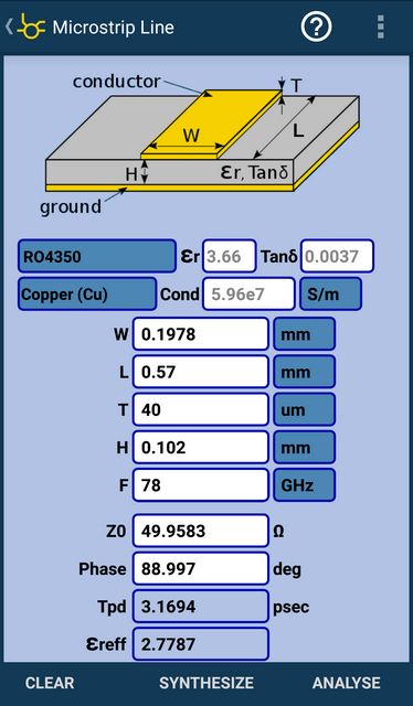
This is a task that everyone who develops devices using PCB technology faces. Not only in the HF or microwave range, but also at lower frequencies. There are two calculation modes - synthesis and analysis. Those. You can specify the necessary impedance and substrate data to obtain the geometry of the desired line. And you can analyze the existing line geometry and get the impedance value for this line.

There is also a built-in directory of the most popular materials for printed circuit boards (PP)
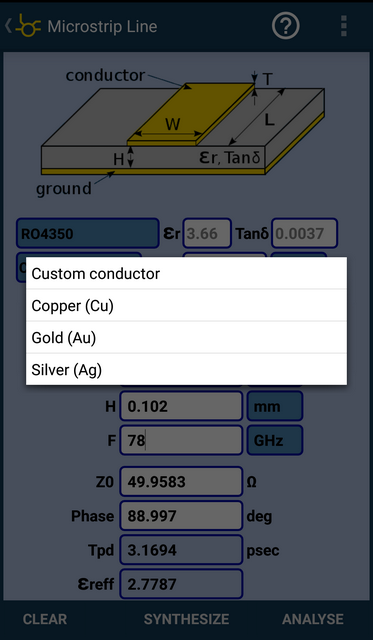
And there is also a directory of the main conductors: copper, gold and silver, i.e. those materials that are widely used in the manufacture of PP.
9. Skin Depth - Skin effect (more precisely, the depth of the skin effect).
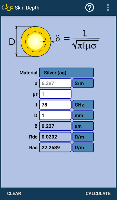
The idea is simple - the higher the frequency, the closer the currents to the surface of the conductor. And in order to understand how deep the RF currents penetrate, this calculator was created.
10. Couplers and Transformers - this is a whole section devoted to taps , dividers and transformers (converters), including and baluns (balun).
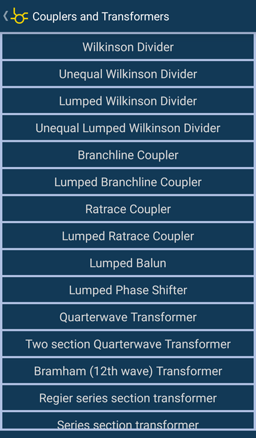
In this section, you can write a whole series of books and articles with explanations and calculations :) Therefore, I will give only a couple of examples.
Wilkinson Divider - Wilkinson (Wilkinson) divider or ring power divider .
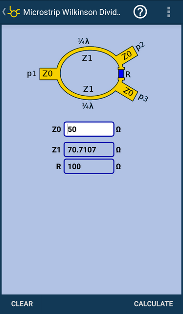
This divider circuit is widely used in many applications and is very popular.
Microstrip coupled line directional coupler is a directional coupler on connected microstrip lines.
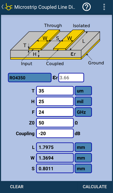
This is not just a divider, but a directional coupler on connected microstrip lines (the length of the connected lines is about 1/4 of the wavelength). Those. branches off some of the signal passing along the transmission line in a certain direction. It can be used, for example, to detect the presence of a signal and determine its level. The device seems to be simple, but there are so many modifications and uses that you can write a whole book.
This concludes the story about the Couplers and Transformers section. If interested, do your own investigation.
11. TRL CalKit ( Calibration Kit ) - Calculation of calibration measures for the TRL standard.
The calculation can be carried out for microstrip lines , stripline, coplanar waveguide ( CPW ) and coplanar waveguide with ground polygon (GCPW).
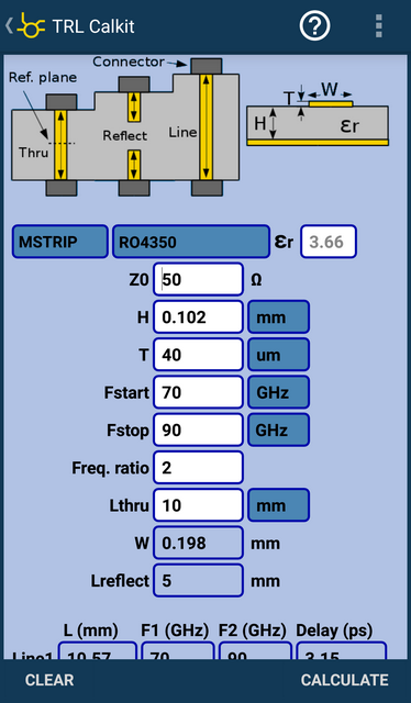
This thing is quite specific, but necessary for everyone involved in the development of planar microwave devices (or devices mounted on a printed circuit board in the microwave path) with their subsequent characterization using a vector network analyzer (VAC).
If interested, here is some information on TRL calibration .
12. Power (dBm) add calculator - a calculator that allows you to calculate the resulting power of several signals (up to four), taking into account the phases.
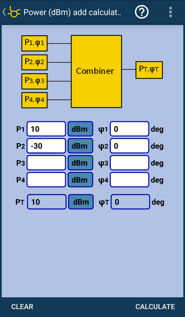
The convenience is that you can add levels expressed in dBm. Those. no need to translate from logarithmic units to linear units and vice versa. Again, it is convenient when you can take into account the effect of the phase on the resulting value of the signal level.
13. PI and TI Attenuators - calculation of “P” and “T” sections of attenuators .
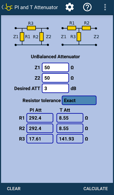
The “P” and “T” sections of the attenuators are used both for the design of fixed attenuators and for tunable ones. They can be used individually or as part of fairly complex circuits (for example, in digital tunable attenuators or AGC systems ).
And this is only a small part of the tools that are present in the RF and Microwave Toolbox.
I note that I have been using this application for several years. And all these years the application has been developing, new functions and possibilities appear in it.
In addition to the full version of the RF & Microwave Toolbox , which is paid, there is also a version of the RF & Microwave Toolbox Lite - a trial version with a small set of functions. Perhaps someone has enough "light" functionality. If you need only one tool, and not the entire toolbox, you can choose from a large set of utilities , most of which are free.
PS Dear habravchane, thank you for your attention!
I would be grateful for the comments on the post and links to similar tools that you use. If the topic you are interested in is interesting, check the box or leave a comment on the publication. Feedback will allow me to understand whether it is worth writing about other tools.
The computational power of modern smartphones is simply amazing. And I really wanted to use these computing resources to perform work calculations. Let simple, but necessarily useful and necessary.
For a long time I surfed the vastness of Google Play and other resources in search of a tool that would satisfy my requests. And at some point in time, the search was successful - I found the RF & Microwave Toolbox . It should be noted that the creator of this wonderful application is the developer of microwave devices (" rf and microwave circuit design "), therefore, the application implements really useful and popular functions. The developer himself says the following about his application:
“This is the best and most advanced High frequency electronics toolbox for Microwave designers, RF professionals, EMC technicians, radio-amateur, students, astronomer and electronic hobbyists.”
Those. The audience is quite wide and it is not only radio engineers, but also radio amateurs, technical specialists in the field of EMC, students, astronomers and those people for whom radio electronics is a hobby.
The application interface looks rather concise, representing a tile, each “brick” of which leads to a separate “calculator” (calculation or tool - “tool”). On the screen of my smartphone fits three pages with a set of "calculators":
Page 1
page 2
page 3
On each page there are about 30 different instruments, on three - almost 90! Therefore, I will not talk about each instrument separately, but only about those that I often use myself. You can learn the rest yourself.
Let's see what is there ...
1. Mismatch Error Limits - the spread associated with the mismatch error.
The VSWR of the source and load in the specified section is introduced and the maximum and minimum VSWR in the line are calculated, as well as a number of associated characteristics (return losses, amplitude and phase errors).
2. Reflectometer - reflectometer (on the VSWR icon).
The input field can be selected in the left column. In the example in the picture, the VSWR field (= 2) was selected and the calculation was performed:
- Return Loss - return loss (S11 module in dB);
- Mismatch loss - mismatch loss (it is clear that only due to the mismatch loss is 0.5 dB);
- Reflected Power - reflected power (it is seen that with VSWR = 2, more than 10% of the useful power is reflected in the "return").
Below are the values of the reflection coefficient (G is the module and phase, the real and imaginary part), load and conductivity.
3. Power and Voltage Converter - conversion from units of power to units of voltage and current, as well as vice versa.
In the presented image, a conversion from logarithmic power units (dBm) was performed. It must be remembered that by default, the calculation is done for a resistance of 50 ohms.
4. Wavelength - calculation of the wavelength.
It is performed for the given frequency and medium parameters (determined by the value of the relative dielectric constant εr). The output is the wavelength and its fraction (1/2, 1/4, 1/8, 1/10), the speed of propagation of electromagnetic waves in the medium (v) and the duration of the oscillation period (τ).
I forgot to say that each calculation has its own help (question mark in the upper right corner of the screen), where you can see by what formulas the calculation is made, how to use the “calculator” correctly.
If necessary, you can save the calculation as a template so that you can quickly return to it later.
5. Patch Antenna - a planar “patch” antenna (meaning a microstrip rectangular patch antenna with an “inset feed” power scheme ).
Not otherwise, this calculation appeared for those involved in the development of planar antenna arrays for subscriber terminals of 5G networks :) Although ... a rectangular patch antenna is used in many antenna solutions - from communication and data transmission systems of various frequency ranges to car radars (24 and 77 GHz). Both in a single form, and in the form of arrays (lattices).
In addition to calculating the patch antenna, there is also a guide to the most popular materials for printed circuit boards (including Rogers ).
This is very convenient because no need to remember this data or look for it somewhere. Just poked into the list and chose the most suitable material.
Of course, this tool does not count the radiation pattern (NAM). But if you are interested in what type of antenna has such an antenna, you can look, for example, here .
6. IP3 - calculation of the “3rd order intersection point” (or determination of the level of intermodulation distortions of the 3rd order).
Honestly, here I am always confused, because the practical value of the IP3 value eludes me all the time. It’s easier for me to operate with the level of 3rd order intermodulation distortion (IMD 3). But in foreign technical literature, as a rule, IP3 is given. And therefore, such a tool for me is just a find, because on the “palm”, without departing from the cash register, so to speak, you can immediately estimate the 3rd order IMD level at the output of the active ( non-linear ) circuit. For the RF path, this is an important indicator, which is discussed in the terms of reference (TOR).
7. Radar Cross Section ( RCS ) - effective scattering surface (or area) ( EPR ).
The picture above shows an example of EPR calculation for a tetrahedral reflective angle with side length L. Similar angles are used to test prototype radar installations when a test “target” with a given value of EPR is needed. And as I understand it, the author and creator of RF and Microwave ToolBox also ran into this problem :)
In addition to the tetrahedron, there are other configurations of corners, and there is also a sphere, a cylinder and a flat reflector (flat plate).
8. Microstrip Line - calculation of the wave impedance ( impedance ) of a microstrip line (asymmetric strip line).
This is a task that everyone who develops devices using PCB technology faces. Not only in the HF or microwave range, but also at lower frequencies. There are two calculation modes - synthesis and analysis. Those. You can specify the necessary impedance and substrate data to obtain the geometry of the desired line. And you can analyze the existing line geometry and get the impedance value for this line.
There is also a built-in directory of the most popular materials for printed circuit boards (PP)
And there is also a directory of the main conductors: copper, gold and silver, i.e. those materials that are widely used in the manufacture of PP.
9. Skin Depth - Skin effect (more precisely, the depth of the skin effect).
The idea is simple - the higher the frequency, the closer the currents to the surface of the conductor. And in order to understand how deep the RF currents penetrate, this calculator was created.
10. Couplers and Transformers - this is a whole section devoted to taps , dividers and transformers (converters), including and baluns (balun).
In this section, you can write a whole series of books and articles with explanations and calculations :) Therefore, I will give only a couple of examples.
Wilkinson Divider - Wilkinson (Wilkinson) divider or ring power divider .
This divider circuit is widely used in many applications and is very popular.
Microstrip coupled line directional coupler is a directional coupler on connected microstrip lines.
This is not just a divider, but a directional coupler on connected microstrip lines (the length of the connected lines is about 1/4 of the wavelength). Those. branches off some of the signal passing along the transmission line in a certain direction. It can be used, for example, to detect the presence of a signal and determine its level. The device seems to be simple, but there are so many modifications and uses that you can write a whole book.
This concludes the story about the Couplers and Transformers section. If interested, do your own investigation.
11. TRL CalKit ( Calibration Kit ) - Calculation of calibration measures for the TRL standard.
The calculation can be carried out for microstrip lines , stripline, coplanar waveguide ( CPW ) and coplanar waveguide with ground polygon (GCPW).
This thing is quite specific, but necessary for everyone involved in the development of planar microwave devices (or devices mounted on a printed circuit board in the microwave path) with their subsequent characterization using a vector network analyzer (VAC).
If interested, here is some information on TRL calibration .
12. Power (dBm) add calculator - a calculator that allows you to calculate the resulting power of several signals (up to four), taking into account the phases.
The convenience is that you can add levels expressed in dBm. Those. no need to translate from logarithmic units to linear units and vice versa. Again, it is convenient when you can take into account the effect of the phase on the resulting value of the signal level.
13. PI and TI Attenuators - calculation of “P” and “T” sections of attenuators .
The “P” and “T” sections of the attenuators are used both for the design of fixed attenuators and for tunable ones. They can be used individually or as part of fairly complex circuits (for example, in digital tunable attenuators or AGC systems ).
And this is only a small part of the tools that are present in the RF and Microwave Toolbox.
I note that I have been using this application for several years. And all these years the application has been developing, new functions and possibilities appear in it.
In addition to the full version of the RF & Microwave Toolbox , which is paid, there is also a version of the RF & Microwave Toolbox Lite - a trial version with a small set of functions. Perhaps someone has enough "light" functionality. If you need only one tool, and not the entire toolbox, you can choose from a large set of utilities , most of which are free.
PS Dear habravchane, thank you for your attention!
I would be grateful for the comments on the post and links to similar tools that you use. If the topic you are interested in is interesting, check the box or leave a comment on the publication. Feedback will allow me to understand whether it is worth writing about other tools.
All Articles