ShIoTiny: a clock without a spring or real time and how to work with it
What is this article about
We continue the series of articles on ShIoTiny - a visually programmable controller based on the ESP8266 chip.
This article talks about the real-time clock in the ShIoTiny controller, time synchronization and the use of nodes for working with the clock.
ShIoTiny Project Site
Previous articles in the series.
ShIoTiny: small automation, the Internet of things, or “six months before the holidays”
ShIoTiny: nodes, links and events or features of drawing programs
ShIoTiny: wet room ventilation (example project)
ShIoTiny and the surrounding world: connecting sensors to binary inputs, contact bounce and other issues
ShIoTiny and the world: analog sensors or ADCs for the smallest
Binary firmware, controller circuitry and documentation
Introduction
Today we talk about time. Not about time, in the sense in which philosophers have been arguing about it for centuries and the end-edge is not visible to this debate. And about the time that we see on the clock and according to which we go to work, to school or in a hurry on a date.
The thing is that the non-volatile real-time clock in the ESP8266 chip and the ShIoTiny controller are missing. This birth trauma to the ShIoTiny controller is entirely my fault. But what has been done is done.
As soon as the firmware saw the light, the public, outraged by my attitude to real time, began to poke my nose at this flaw.
Since the errors need to be fixed, and this time at least not with blood, I went to meet the ever-increasing number of users of my firmware and did what I could. Namely, I added nodes to the firmware of the ShIoTiny controller that make it more or less convenient to work with this in real time.
About ShIoTiny Watch
As already mentioned, there are no “hours with a battery” in ShIoTiny . But at the same time, the countdown of seconds starting from January 1, 1970 is implemented.
This is the same time called UNIX-time, stored in variables of type time_t in C / C ++ languages and which should end on January 19, 2038 in 32-bit systems.
But do not be afraid. I think that by 2038 everyone will have time to make the time_t type 64-bit and the problem will be solved in the next 292 billion years. Well, there’s something else we’ll come up with.
Note that time in the time_t format is sometimes called (in my article, too) - timestamp or, in Russian, a timestamp .
But back to our controller. So, there is a clock in it, but this clock is reset to 0 after turning off the power. This leads to the trivial conclusion that the main problem of counting time in the ShIoTiny controller is the need to synchronize the controller clock when the power is turned on. The rest is purely technical problems.
Time synchronization
A long-established way to synchronize time on the Internet is NTP servers. And the first idea was to make a node that synchronizes time with a given NTP server.
But, breathing a little fresh air and pondering my pumpkin, I realized that this approach is ideologically wrong.
It is not a fact that the user wants to pull out the controller with ShIoTiny firmware on the Internet. And time for synchronization can be sent not only from the NTP server, but also via UDP-multicast, or with a known connection quality - via MQTT .
Therefore, a fateful decision was made - to separate the nodes for receiving time from the NTP server and setting the system time.
In total, two nodes were developed for time synchronization: a node for receiving time from an NTP server NTP Time

and Set Time system clock installation node

The node receiving time from the NTP server as parameters receives the name or IP address of the NTP server and, separated by a comma, the time request period from the NTP server in minutes. By default, time is requested from the NTP server every 60 minutes or 1 hour. At the output, this node sets 0 until the time is synchronized or the time stamp is the result of the last synchronization with the server.
The system clock installation node receives a time stamp as an input and sets the system clock in accordance with this label.
The simplest scheme for synchronizing the system clock with an NTP server is shown in the figure.
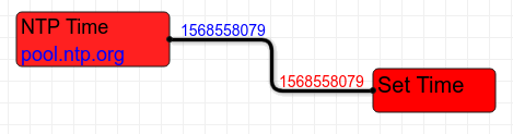
The synchronization period is not set and defaults to 60 minutes. The figure shows the time stamp.
I note that there can be no more than one node for receiving time from an NTP server and more than one node for setting the system time in the program scheme.
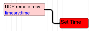
If you need an exotic synchronization scheme, then you can use UDP-multicast or MQTT . The schemes are completely similar.
For UDP-multicast synchronization, approximately the same as in the figure.
And for synchronization via MQTT (I do not advise, of course, but in extreme cases) - such.

I hope that now everything is clear with the synchronization of the system clock of the ShIoTIny controller. Let's move on to the nodes for receiving and processing time.
What time is it now?
The question is simple, but sometimes it’s not easy to answer. After all, time at every point on the Earth is different. Our vast Motherland includes from Kaliningrad to Kamchatka as many as 11 time zones.
The NTP server, depending on the settings, can return a timestamp associated with different time zones. Typically, this timestamp is tied to UTC - universal time.
But usually we need the local time of the region where our controller works. How to be here?
And it’s very simple - to get the time stamp of the ShIoTIny controller’s system clock, the Get Time node was developed, in which you can set the time zone as a time offset from -12 hours to +12 hours relative to the controller’s system clock.
Suppose we get the time from the server pool.ntp.org and synchronize the system clock, as in our example earlier. This server returns universal time. We need local, like Tomsk, like mine. I know that Tomsk is in the UTC + 7 time zone. So, let's set the time receiving unit to offset +7 or just 7. As in the figure below.

And if we lived in the Canadian province of Alberta, the shift would be -7 hours. Remember the main thing - the time zone is set in the node for obtaining time in hours . And it is set in the form of an offset relative to the time of the system clock. At the output of the time receiving unit, a time stamp is set. There can be several nodes for obtaining time on a circuit.
Check the clock
The machine is very convenient to work with time in the format of timestamps time_t . After all, this is just an integer that shows the number of seconds relative to the starting point - January 1, 1970. In this format, you can easily find the distance between two time points, count periods and so on. This is just the addition and subtraction of integers.
But man is not a machine. He is much more comfortable with the usual representation of time in the form of a year, month, day, hours, minutes and seconds. So we humans are arranged.
Therefore, the nodes of the conversion of the time stamp into the units of time change familiar to the person were introduced, and vice versa, the synthesis of the time stamp from the units of change of time understandable to the person. These nodes are called, respectively, Split Time and Synth Time .
How all this works is clear from the figure below.
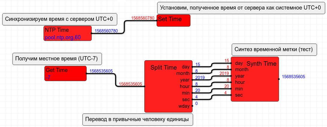
I note that the nodes Split Time and Synth Time months (month) and days of the week (wday) are counted from zero. For months: 0-January, 11-December. For days of the week 0-Sunday, 6-Saturday.
Other outputs: day of the month (day), year (year), hour (hour), min (minute), sec (second) - are counted in the usual form. Hours, minutes, seconds - from 0 to 59. Day of the month - depending on the month from the first day to the 30th or 31st and, for February, to 28 or 29th.
Well, a year - he is the year. 2019 now.
I hope everything is clear.
System example
In order not to be unfounded, I will give an example of the use of watches. Of course, simplified.
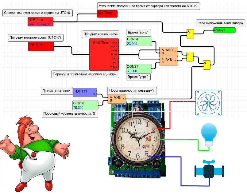
Suppose we have a humid room that we want to force-ventilate. But not always, but only when the humidity is higher than a given level and only at night. At night - so as not to disturb people during the day with the noise of fans. Well, here we are aesthetes and take care of people.
Let's try to implement this.
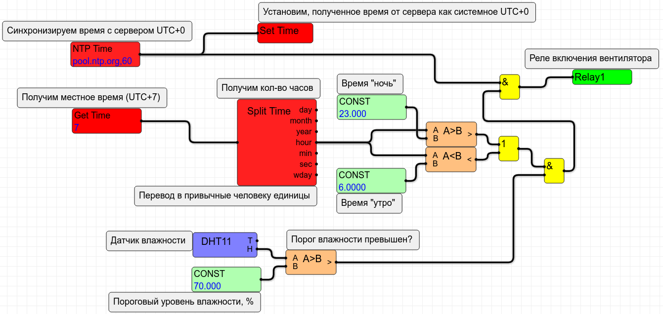
All parts of the circuit are familiar to us. The time is synchronized from the NTP server. While it is not synchronized, the NTP Time node returns 0 and the fan enable relay is disabled. For this, the top element And according to the scheme is responsible.
Once the time is synchronized, the on / off of the fan is determined by the current time and humidity level. As soon as the humidity level exceeds 70% and the time is from 23:00 to 06:00 - the fan will turn on and not disturb anyone to ventilate the room.
Of course, it is better to replace the time and humidity constants in a real project with the parameters stored in FLASH and set, for example, according to MQTT . Yes, and the current state of the system - humidity level, current, time, fan status - also does not hurt to publish on the network to control the system from a smartphone. But this already I leave room for your imagination.
Conclusion
So we introduced our controller with real time closer.
I want to thank everyone who sent me letters of constructive criticism and advice on software upgrades. Thanks guys!
As usual - constructive criticism is welcome. In addition, comments and suggestions are welcome.
You can send all criticism, comments, suggestions as usual in a comment or mail: shiotiny@yandex.ru .
All Articles