AudioSwitcher - automation of what would seem no need to automate
Foreword
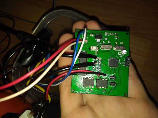
I have a couple sets of good Soviet speaker systems at home. But this technique is quite old and simply cannot turn on from the remote control or automatically, but constantly approach the sound amplifier and turn it on / off just lazy. I solved this problem. At first, Arduino was bought and the project was done on it, but the quality of work did not suit me and the project was redone for STM32F103C8. As a result, I got a device that has 4 audio inputs, 1 audio output, 220V input and 220V output. If there is at least one active audio input, a voltage appears at the 220V output, thereby including a sound amplifier, and the active audio channel is transmitted to the output.
Development Challenges
It would seem that everything is simple: if the ADC receives not 0, then consider the channel as active. Almost everything is, but it only works if you turn on the source of the audio signal and turn off the sound on it. When turned off, different devices give different interference, since they are not completely de-energized. And with bad sound sources, the microcontroller could pick up noise when the sound was turned off, and quite strong. And this is precisely the source interference, the STMka does not see interference on my external audio card, moreover, the quiet sound from it is 0.
How to do it yourself?
Let us first decide what we need. I will not write the cost, because it depends a lot on your location.
What we need:
- printed circuit board
- programmer ST-Link v2
- 1 chip STM32f103C8
- 4 relays for switching the input audio channel to the output
- 1 relay for switching 220V to turn on the amplifier
- AC-DC buck converter 220V - 5V (can be taken from an old phone charge)
- mains cable and connector for supplying current to our device and amplifier
- power socket
- resistors, capacitors and other small things
Naturally, we need audio wires and a minijack plug with sockets.
I would like to focus on the choice of relay ... If everything is very clear with the choice of 220V relay: it should be able to “switch” 220V alternating voltage and be controlled by 3.3V. The choice of sound relays is not so simple. Not every relay, even a solid-state one, will give interference at the output, and this is very important for us. I live in Minsk and could not find anything suitable and at a reasonable price, so 4 PVT322A relays were ordered from a well-known Chinese store. Perhaps in your area you can find something cheaper.
Scheme and wiring
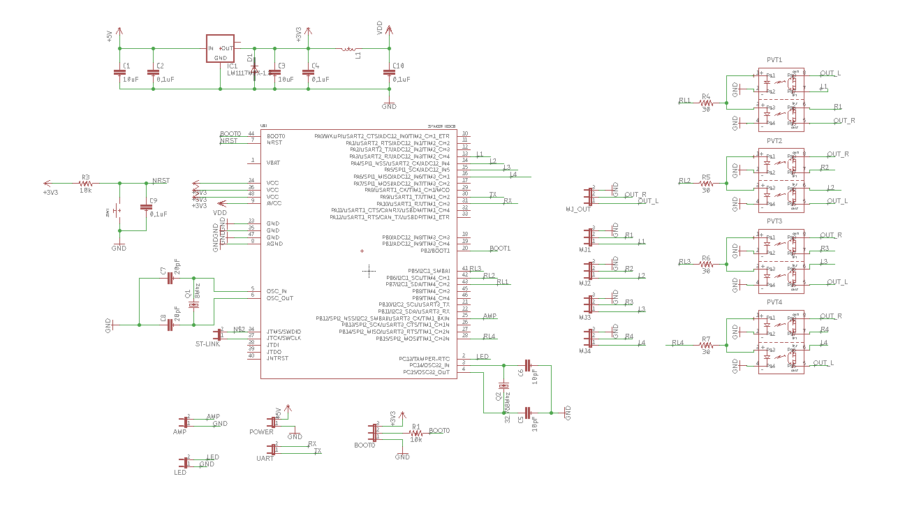
Since we started, we will continue to study the hardware features. In the diagram that you can find in the repository in the Eagle folder, you need to select current-limiting resistors (R4-7) for your relays. In my case, it's 30 ohms. There is also an L1 coil: choose any filter that smooths high-frequency noise.
You can order a printed circuit board on PCBWAY or JLCPCB. Their prices are low, I ordered from JLCPCB and they billed me only $ 2. When ordering a printed circuit board, you will need gerber files, you can find everything from the same folder or generate it yourself.
Let's move on to the software part
I will not talk about how to connect the programmer to the computer, install the programming environment and driver, because There are a lot of these instructions and they are extremely accessible. On my circuit outputs for programmers are provided. I used Visual Studio 2017 + VisualGDB. After downloading the project from the same repository, we can open the project. Immediately turn to the Settings.cpp file.
Settings.cpp
#define DEBUG0 0//init USART and send all measurement values #define DEBUG1 1//init USART and send information about recognition music or not #define DEBUG2 0//just init USART #define MaxEqualToZeroValue 3 //the value which equal or less is equated to zero #define MaxAvarageForNoise (float)0.4//this is max avarage of measurement values so that the sound is considered noise for NOT active channel #define MaxAvarageForActiveNoise (float)0.06//this is max avarage of measurement values so that the sound is considered noise for active channel #define CountOfConsecutiveZeroValueForNoise 250//if count of consecutive zero values bugger it that sound is equated to noise #define MinCountOfZeroValue 550//it's minimum count of zero values to equate to music(not consecutive) #define USE_LED 1 #define LED_GPIO_PERIPH RCC_APB2Periph_GPIOC #define LED_GPIO_GROUP GPIOC #define LED_GPIO_PIN GPIO_Pin_13 #define USE_AMP 1 #define AMP_GPIO_PERIPH RCC_APB2Periph_GPIOB #define AMP_GPIO_GROUP GPIOB #define AMP_GPIO_PIN GPIO_Pin_12
All settings in this file are documented, but we will still dwell on each setting.
#define DEBUG0 0 #define DEBUG1 1 #define DEBUG2 0
If we assign a unit to DEBUG0, our device will stop doing anything except that it will output the values it receives from the audio inputs in a format that SerialPortPlotter can “digest” using UART.
If you assign the unit DEBUG1, then the device will already be fully operational, but it will display a little information about the work on UART. All this is necessary exclusively for debugging.
Assignment of DEBUG2 will only give initialization of the UART. If you don’t understand why this is, then don’t :-)
#define MaxEqualToZeroValue 3
Next, we have a parameter whose corresponding value or less will be considered zero. As mentioned earlier, some sources of sound are of poor quality and very noisy.
#define MaxAvarageForNoise (float)0.4
If the audio channel is currently inactive (i.e., the channel that is not currently switched to output) and the average measurement value for one measurement cycle on this channel is less than the value of this parameter, then the channel is considered without sound.
#define MaxAvarageForActiveNoise (float)0.06
This parameter is almost the same as the previous one, only for the channel that is currently active. The fact is that when the channel is active and the amplifier is working, the voltage of the audio channel drops. And if you neglect this setting, the device will consider that there is sound even when the wire is not connected to any device.
#define CountOfConsecutiveZeroValueForNoise 250
This parameter is solely for optimizing CPU consumption. If the device meets a predetermined number of zeros in a row, then it considers that this signal is not a sound.
#define MinCountOfZeroValue 550
And this is an important setting. Some devices, when turned off, create strange noise, but I highlighted one common factor among them: they very rarely drop to zero values. That is why I had to enter this parameter. If the number of zero values for one measurement cycle is less than the specified value, then the signal is considered noise.
#define USE_LED 1 #define LED_GPIO_PERIPH RCC_APB2Periph_GPIOC #define LED_GPIO_GROUP GPIOC #define LED_GPIO_PIN GPIO_Pin_13 #define USE_AMP 1 #define AMP_GPIO_PERIPH RCC_APB2Periph_GPIOB #define AMP_GPIO_GROUP GPIOB #define AMP_GPIO_PIN GPIO_Pin_12
This block is extremely understandable for those who have already programmed microcontrollers. He selects the pin on which the LED will be located and the output to the amplifier control relay. If you will not change my scheme, then you do not need these parameters.
Let's move on to the following settings:
By opening the main.cpp file, at the very beginning of the function
int main()
You will find a definition of a bunch of variables.
Let us dwell on this in more detail. There are a lot of parameters responsible for the hardware configuration of the microcontroller. We will not touch them.
const uint8_t channelsCount = 2;
This is the number of audio input channels to be used.
const uint8_t countOfIterationsForSwitch = 5;
The number of measurement cycles required to change the active / passive state.
const uint8_t ADCSampleTime = ADC_SampleTime_239Cycles5;
This parameter is responsible for the quality of the measurement. It is set to maximum, I do not recommend changing it.
const uint16_t measurementsDuration = 2000;
This is the time in ms during which one measurement cycle will be performed.
const uint32_t measurementFrequencies[] = { 1000, 1000, 1000, 1000 };
I don’t know why, but I implemented a function that allows me to measure input channels with different frequencies for each channel. Maybe someone will need this feature.
Conclusion
OK it's all over Now. I have described all the necessary settings. It remains only to assemble the circuit, compile the project, fill the firmware into the microcontroller and rejoice.
In conclusion, I would like to say that you can’t just leave the input audio wire “not stuck” in anything, you need to insert it into any device or plug in the form of a minijack jack in which all the contacts are interconnected.
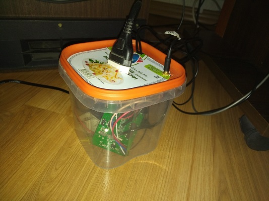
If your sound sources are pretty good, then you can set low settings, but switching the sound state may require turning it off (not from an outlet). Maybe someday I will add a link to the 3D model of the case, but so far I do not have a 3D printer and the case is currently such. But this is only for now: the 3D printer is already going :-)
This is my first article, I will be glad to any reasoned criticism. I understand that this is not a masterpiece, but I tried my best.
Thanks for reading.
UPD1: Added schematic and wiring images in the article.
UPD2: Added schematic and wiring images to the repository, added new comments in the code.
All Articles