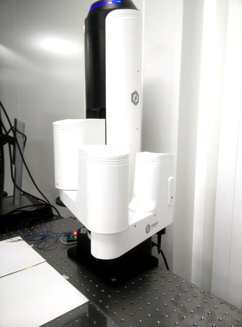
We work with the cobot Dobot M1
A year ago on Habré the review of the desktop robot Dobot Magician came out. In this article, I propose evaluating his older brother Dobot M1 in action. I will also try to explain why I chose this particular model for my project, I will describe the development process of the demo in Qt / c ++, as well as some unpleasant moments that I encountered during the development process.
This year I worked at one of the most common research institutes. At first, everything was quite casual, and the year did not promise anything interesting, until one day at a rally a discussion began on how to make tiled assembly of solar cells (shingled solar cells). This approach is nothing new, they say , this is one of the first ways to assemble panels for space satellites.
I do not know how true this is because I have not seen articles or patents. But the public’s interest in this decision has warmed up, partly also because a couple of years ago SunPower rolled out its new panels, which it called the P-series . It just so happened in the world of photovoltaics that since the sanpower is doing something, then everyone must do this thing too. There we are. Everything is simple: we prepare the substrates, cut them into strips and assemble. At that moment, I noted that I personally would definitely not collect anything manually, because my hands did not differ in particular evenness. Otherwise, the result may be something like one video on YouTube. And we, after all, are a whole institution, if we really do something, it’s not so collective farm. I offered to buy robots and configure them for the desired process, and they gave me the go-ahead.
It should be noted that we decided to start easier and collect mini-panels. A mini-panel is any solar panel that is smaller than standard. We do this for working out technological processes. First, I was guided by a panel with a size of 1 standard solar cell with scaling plans to a panel of 2 x 2. The size of the side of one solar cell is 16 cm. Accordingly, robots were needed with an access field of 32 x 32 cm. I wanted to get more accurate accuracy and cheaper price . So, armed with a search bar, I began to study the sentences. I decided that 6 axes are not needed for the project, 4 are enough, so the choice was narrowed to robots like a scar. I found out that buying industrial robots is accompanied by additional expenses, such as designing a safe workspace and leaving the application engineer at the installation site, which programs the robot for your task. Good industrial robots are expensive in principle, and the services of engineers will increase the price tag even more, moreover, it was interesting to implement the project yourself. Therefore, the choice narrowed down to cobots, collaborative robots, with lower security requirements and more friendly for self-prototyping. So, I quickly found the Dobot company. I immediately dropped the Dobot Magician because of the size and accuracy, which is 100 microns. I wrote a request for them to give specs and say where to buy. I found out that with APIs there are APIs and they can be programmed in C ++. It suited me, but I couldn’t just buy it directly. Fortunately, I found one supplier in the Netherlands, who sold me 2 pieces for 8700 euros with VAT, with delivery from China, and at the same time took over all the customs clearance.
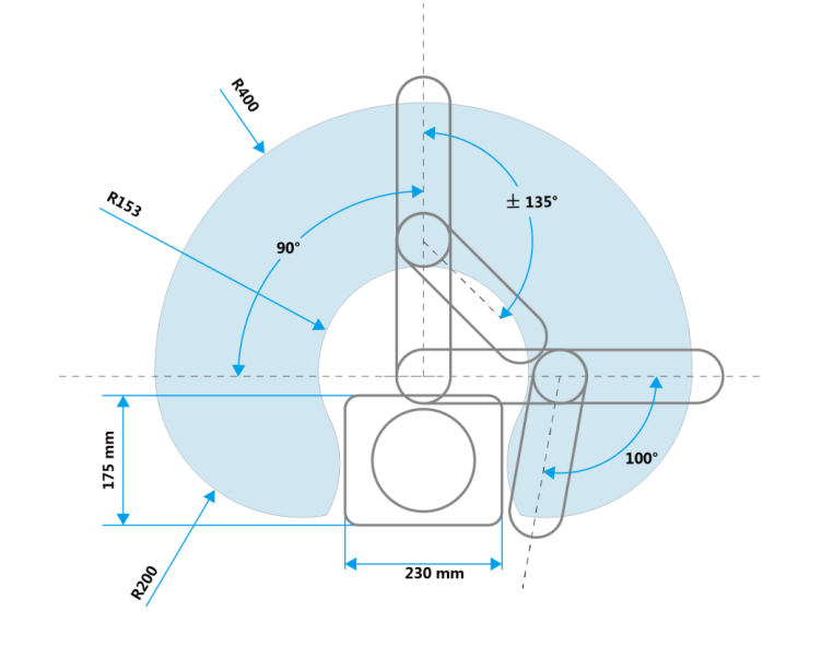
Dobot M1 is positioned as an affordable professional 4-axis collaborative robot. It can withstand up to 1.5 kg of load (not tested), has a range of up to 400 mm (not everywhere) and accuracy up to 20 microns (checked). The workspace of kindness is seen in the figure below. It is not difficult to notice that due to the design features there is a blind zone with a radius of slightly less than 15 centimeters in front. Moreover, this space map does not take into account the orientation of the hand. Dobot can be either right-handed or left-handed, I still have not figured out how this can be switched on the go without additional calibration. By default, Dobot is right-handed, which means that the right zone is limited by the access area of the 2nd joint, when the first joint is directed to the right. So the real area of the workspace is about 2/3 of what is shown in the official drawing.
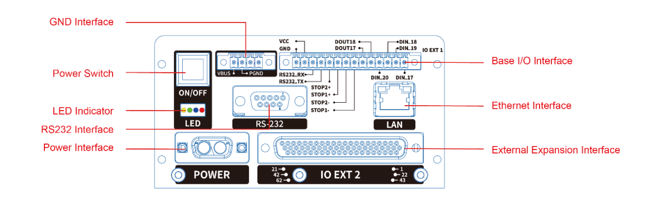
Goodness has I / O ports: digital inputs and outputs with 24 V levels (default levels are high), as well as analog inputs. What kind of ADC is there, I do not know. Ports are available on the rear panel in the stand and on the hand itself for working with nozzles. I forgot to photograph the connector on the arm itself, but it’s a type of CAA. There is also an expansion interface for which you can buy an additional fee. Dobot connects to a PC via RS-232 or over a network.
Housing materials: polycarbonate, apparently, plus a metal stand painted in black. This design does not cause a sense of premium, but also a sense of artisanism, too. I bought one fully loaded, and one in the base. I did not test the laser nozzle and 3D printing.
To test the goodness of kindness, I used the M1Studio program for Windows, which is downloaded from the company's website. But that’s all. Further, armed with api, Qt and a workstation with elementary wasps, I sat down to write a demo to work with several dos.
Actually, the demo is already available on the github . Documentation for API and communication protocol can be downloaded from the manufacturer’s website.
First of all, we used the SearchDobot () method from api, which did not give out anything under Linux, and only worked in windows if the dobot were connected via RS-232. It’s strange, because M1Studiya perfectly defines dobotov over the network. With known ip addresses, the ConnectDobot () method works just fine. It's okay, I thought, I'll set up the router and let the ip address be attached to the poppy. The next day I was surprised at the fact that kindnesses do not react. It turned out that when turned on, Dobot has a random poppy address. This is such a feature of the firmware, which was fixed in the new version in May, but which I, however, was afraid to install.
Armed with a program for analyzing network packets, I found out that Dobot respond to UDP request to port 6000 with the text “WhoisDobotM1” UDP response with text containing the model number of Dobot. Based on this, a custom method was written that sends requests across the entire subnet, and in the case of a response, initializes kindness.
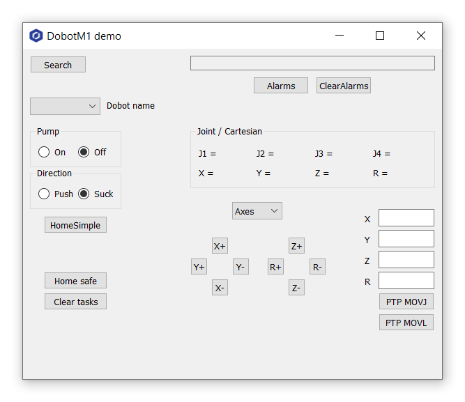
The demo interface is quite simple and is presented in the picture below.
To initialize and control kindness, I wrote a class in which I implemented the functions I needed: axis control, movement from point to point in a straight line and in a curve, return to the initial position, control of the air pump, as well as monitoring of positions and errors. Let's take turns. When the class is initialized, the ip-address of kindness is stored in the variable, the first connection to it occurs, the entire queue of commands is cleaned, even if the queue is empty, and the acceleration and speed parameters for motors are set.
I decided to use a vector with elements of my class to control dobot, when their number is more than 1. Each element of the vector has a variable that stores the ip address of the dobot. Because the library is one, and there are several dobotov, then in each method of the class you must first call the method of connecting to a specific dobot. It may look crooked, but it's all under the hood, and then working with this class is very convenient.
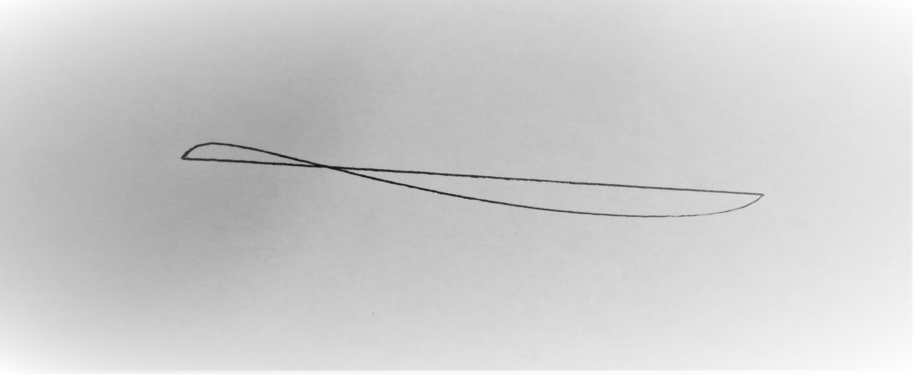
Movement from point to point in API Goodness is implemented by several methods: in a straight line, in a curve, and in some other way that I do not remember. The figure below shows two trajectories between 2 points. One is a straight line, which with proper calibration of the device does not bifurcate when moving back and forth. The second trajectory is the curved line that you get, because the kindness firmware sequentially adjusts the motors to achieve the desired coordinate. It should be noted that the movement in a straight line is not always possible, some positions of the joints do not make it possible to reach from point A to point B in a straight line.
Dobot position monitoring is implemented using the Qtimer class, whose Qtimer :: timeout signal is tied to my MainWindow :: on_getPoseTimer method. I must admit, this is a so-so solution, because responsive work of the application with ups is possible only if you set a timeout of 1000 ms. With shorter timings, jerks begin to be felt when managing the ups. I noticed that sometimes a dobot can stupid for a while when a command is received, and if you send commands quite often, then the probability of getting a stupid rises. Perhaps this is due to the constant call to ConnectDobot, which may seem unnecessary in this demo, but the demo was written in parallel with the main project, and in the main project I really need such an implementation. However, to monitor the connection is not called every time, but the problem with the suspension remains. A timeout of 1 s, unfortunately, does not provide such a smooth measurement of the position of kindness in space, which, for example, is implemented in the M1 Studio, but, on the other hand, this is not important.
In the same method, a request for errors occurs. In api kindness, error code transmission is implemented through the AlarmState structure.
This structure is an array of 8-bit elements, and the error code is encoded in the binary representation of one of the several elements of the array. To calculate the error code, you need to find “1” in the element and add its discharge number (unit) to 8 * n elements (containing or not containing other errors) before it in the value array. Yes, there can be more than one mistake at a time. Next, the error code must be found in the document, which is available for download on the manufacturer’s website. The contents of pdfk was copied to a text file, which is bolted to the project as a resource. If the error code differs from 8 * 32 (i.e. there is no error), then this code appears in the error field and by clicking on the Alarm button its description is parsed in the file, and then displayed in the text field. By the way, error decoding and parsing are done outside of the class for managing upsets. What now seems to me not quite the right idea.
An air pump is included in the kit, which in the instruction manual suggests connecting to digital outputs 17 and 18. One output controls the on / off of the pump, and the second controls the direction of air movement. Thus, for example, a pneumatic gripper is activated, which is also supplied.
In the process of exploiting the Dobot, I ran into some troubles.
Kindness allowed me to implement a project to assemble solar cells in a tiled mini-socket, which can be seen on video. Positioning accuracy was checked on the same silicon wafers and was in the limit of 1 pixel on one axis and 10 pixels in another. The camera in this project was used with a resolution of 20 MP, and the camera's field of coverage along the long side was about 17 cm, it is not difficult to calculate that 1 pixel corresponded to a linear size of about 30 microns. It just so happened that the optics used, albeit of high quality, make it possible to observe clearly silicon wafers only in their center, while the edges of the wafers become very blurry, which leads to an uncertainty in the determination of their faces along short sides, and accordingly to an uncertainty in determining the center of the wafer. After calibrating the axes, I set the camera focus to the short sides of the plates. It should be noted that, in principle, it was impossible to focus there as in the center of the field of view, but still. Because of this effect, the positioning error along the axis along the long side of the solar cell was in the limit of 10 pixels, but only 1 pixel on the short side. Which corresponds to approximately 300 and 30 microns. This allowed me to verify the integrity of the specs for accuracy.
Introduction
This year I worked at one of the most common research institutes. At first, everything was quite casual, and the year did not promise anything interesting, until one day at a rally a discussion began on how to make tiled assembly of solar cells (shingled solar cells). This approach is nothing new, they say , this is one of the first ways to assemble panels for space satellites.
I do not know how true this is because I have not seen articles or patents. But the public’s interest in this decision has warmed up, partly also because a couple of years ago SunPower rolled out its new panels, which it called the P-series . It just so happened in the world of photovoltaics that since the sanpower is doing something, then everyone must do this thing too. There we are. Everything is simple: we prepare the substrates, cut them into strips and assemble. At that moment, I noted that I personally would definitely not collect anything manually, because my hands did not differ in particular evenness. Otherwise, the result may be something like one video on YouTube. And we, after all, are a whole institution, if we really do something, it’s not so collective farm. I offered to buy robots and configure them for the desired process, and they gave me the go-ahead.
It should be noted that we decided to start easier and collect mini-panels. A mini-panel is any solar panel that is smaller than standard. We do this for working out technological processes. First, I was guided by a panel with a size of 1 standard solar cell with scaling plans to a panel of 2 x 2. The size of the side of one solar cell is 16 cm. Accordingly, robots were needed with an access field of 32 x 32 cm. I wanted to get more accurate accuracy and cheaper price . So, armed with a search bar, I began to study the sentences. I decided that 6 axes are not needed for the project, 4 are enough, so the choice was narrowed to robots like a scar. I found out that buying industrial robots is accompanied by additional expenses, such as designing a safe workspace and leaving the application engineer at the installation site, which programs the robot for your task. Good industrial robots are expensive in principle, and the services of engineers will increase the price tag even more, moreover, it was interesting to implement the project yourself. Therefore, the choice narrowed down to cobots, collaborative robots, with lower security requirements and more friendly for self-prototyping. So, I quickly found the Dobot company. I immediately dropped the Dobot Magician because of the size and accuracy, which is 100 microns. I wrote a request for them to give specs and say where to buy. I found out that with APIs there are APIs and they can be programmed in C ++. It suited me, but I couldn’t just buy it directly. Fortunately, I found one supplier in the Netherlands, who sold me 2 pieces for 8700 euros with VAT, with delivery from China, and at the same time took over all the customs clearance.
Features kindness
Dobot M1 is positioned as an affordable professional 4-axis collaborative robot. It can withstand up to 1.5 kg of load (not tested), has a range of up to 400 mm (not everywhere) and accuracy up to 20 microns (checked). The workspace of kindness is seen in the figure below. It is not difficult to notice that due to the design features there is a blind zone with a radius of slightly less than 15 centimeters in front. Moreover, this space map does not take into account the orientation of the hand. Dobot can be either right-handed or left-handed, I still have not figured out how this can be switched on the go without additional calibration. By default, Dobot is right-handed, which means that the right zone is limited by the access area of the 2nd joint, when the first joint is directed to the right. So the real area of the workspace is about 2/3 of what is shown in the official drawing.
Goodness has I / O ports: digital inputs and outputs with 24 V levels (default levels are high), as well as analog inputs. What kind of ADC is there, I do not know. Ports are available on the rear panel in the stand and on the hand itself for working with nozzles. I forgot to photograph the connector on the arm itself, but it’s a type of CAA. There is also an expansion interface for which you can buy an additional fee. Dobot connects to a PC via RS-232 or over a network.
Housing materials: polycarbonate, apparently, plus a metal stand painted in black. This design does not cause a sense of premium, but also a sense of artisanism, too. I bought one fully loaded, and one in the base. I did not test the laser nozzle and 3D printing.
To test the goodness of kindness, I used the M1Studio program for Windows, which is downloaded from the company's website. But that’s all. Further, armed with api, Qt and a workstation with elementary wasps, I sat down to write a demo to work with several dos.
We are writing a demo
Actually, the demo is already available on the github . Documentation for API and communication protocol can be downloaded from the manufacturer’s website.
First of all, we used the SearchDobot () method from api, which did not give out anything under Linux, and only worked in windows if the dobot were connected via RS-232. It’s strange, because M1Studiya perfectly defines dobotov over the network. With known ip addresses, the ConnectDobot () method works just fine. It's okay, I thought, I'll set up the router and let the ip address be attached to the poppy. The next day I was surprised at the fact that kindnesses do not react. It turned out that when turned on, Dobot has a random poppy address. This is such a feature of the firmware, which was fixed in the new version in May, but which I, however, was afraid to install.
Armed with a program for analyzing network packets, I found out that Dobot respond to UDP request to port 6000 with the text “WhoisDobotM1” UDP response with text containing the model number of Dobot. Based on this, a custom method was written that sends requests across the entire subnet, and in the case of a response, initializes kindness.
void MainWindow::on_buttonSearch_clicked() { QHostAddress host; QList<QHostAddress> list = QNetworkInterface::allAddresses(); for (int i=0; i<list.count(); i++) { if ((!list.at(i).isLoopback()) && (list.at(i).protocol() == QAbstractSocket::IPv4Protocol)) host = list.at(i); } QString subnet = host.toString().section('.',0,2) + "."; QByteArray data = "WhoisDobotM1"; QUdpSocket udpSocketSend; udpSocketSend.writeDatagram(data);//need tocall it otherwise in Win get socket doesn't open udpSocketSend.bind(host, 54321, QAbstractSocket::ShareAddress); udpSocketGet.bind(host, udpSocketSend.localPort(), QAbstractSocket::ShareAddress); connect(&udpSocketGet, &QUdpSocket::readyRead, this, &MainWindow::readUdpData); for (int i=1; i<255; i++) udpSocketSend.writeDatagram(data, 32, QHostAddress(subnet + QString::number(i)), 6000); }
void MainWindow::readUdpData() { while (udpSocketGet.hasPendingDatagrams()) { QNetworkDatagram data = udpSocketGet.receiveDatagram(); QByteArray ip = data.senderAddress().toString().toUtf8(); QString name = QString(data.data()).section('_',0,0); // cuts "dobotM1" from "dobotM1_Dobot M1_0033\x00" if (name == "dobotM1") { MyDobot* a = new MyDobot(); dobot->push_back(a); dobot->last()->initDobot(ip); ui->listDobots->addItem(ip); on_listDobots_activated(ui->listDobots->currentIndex()); } } }
The demo interface is quite simple and is presented in the picture below.
To initialize and control kindness, I wrote a class in which I implemented the functions I needed: axis control, movement from point to point in a straight line and in a curve, return to the initial position, control of the air pump, as well as monitoring of positions and errors. Let's take turns. When the class is initialized, the ip-address of kindness is stored in the variable, the first connection to it occurs, the entire queue of commands is cleaned, even if the queue is empty, and the acceleration and speed parameters for motors are set.
class MyDobot : public QObject { Q_OBJECT public: explicit MyDobot(QObject *parent = nullptr); ~MyDobot(); void initDobot(QByteArray IPaddress); Pose getCurrentPosition(); void goHomeSafe(); void goHome(); void goSafe(); void goPosition(float x, float y, float z, float r); void goPositionStraight(float x, float y, float z, float r); void goJog(int index); void setAirPump(int status, int direction); //status 1 off 0 on; direction 0 suck 1 push void setOutput(uint8_t address, uint8_t level); void setMotor(int velocity, int acceleration); alarmState getAlarms(); void clearAlarms(); void clearQueue(); QString getName(); public slots: private: char deviceSN[64]; char deviceName[64]; QByteArray thisDobotIP; Pose currentPosition, futurePosition; };
I decided to use a vector with elements of my class to control dobot, when their number is more than 1. Each element of the vector has a variable that stores the ip address of the dobot. Because the library is one, and there are several dobotov, then in each method of the class you must first call the method of connecting to a specific dobot. It may look crooked, but it's all under the hood, and then working with this class is very convenient.
void MyDobot::setAirPump(int status, int direction) { ConnectDobot(thisDobotIP, 115200, nullptr, nullptr); ...
Movement from point to point in API Goodness is implemented by several methods: in a straight line, in a curve, and in some other way that I do not remember. The figure below shows two trajectories between 2 points. One is a straight line, which with proper calibration of the device does not bifurcate when moving back and forth. The second trajectory is the curved line that you get, because the kindness firmware sequentially adjusts the motors to achieve the desired coordinate. It should be noted that the movement in a straight line is not always possible, some positions of the joints do not make it possible to reach from point A to point B in a straight line.
Dobot position monitoring is implemented using the Qtimer class, whose Qtimer :: timeout signal is tied to my MainWindow :: on_getPoseTimer method. I must admit, this is a so-so solution, because responsive work of the application with ups is possible only if you set a timeout of 1000 ms. With shorter timings, jerks begin to be felt when managing the ups. I noticed that sometimes a dobot can stupid for a while when a command is received, and if you send commands quite often, then the probability of getting a stupid rises. Perhaps this is due to the constant call to ConnectDobot, which may seem unnecessary in this demo, but the demo was written in parallel with the main project, and in the main project I really need such an implementation. However, to monitor the connection is not called every time, but the problem with the suspension remains. A timeout of 1 s, unfortunately, does not provide such a smooth measurement of the position of kindness in space, which, for example, is implemented in the M1 Studio, but, on the other hand, this is not important.
In the same method, a request for errors occurs. In api kindness, error code transmission is implemented through the AlarmState structure.
struct alarmState { uint8_t value[32]; };
This structure is an array of 8-bit elements, and the error code is encoded in the binary representation of one of the several elements of the array. To calculate the error code, you need to find “1” in the element and add its discharge number (unit) to 8 * n elements (containing or not containing other errors) before it in the value array. Yes, there can be more than one mistake at a time. Next, the error code must be found in the document, which is available for download on the manufacturer’s website. The contents of pdfk was copied to a text file, which is bolted to the project as a resource. If the error code differs from 8 * 32 (i.e. there is no error), then this code appears in the error field and by clicking on the Alarm button its description is parsed in the file, and then displayed in the text field. By the way, error decoding and parsing are done outside of the class for managing upsets. What now seems to me not quite the right idea.
An air pump is included in the kit, which in the instruction manual suggests connecting to digital outputs 17 and 18. One output controls the on / off of the pump, and the second controls the direction of air movement. Thus, for example, a pneumatic gripper is activated, which is also supplied.
Weeds
In the process of exploiting the Dobot, I ran into some troubles.
- The holes in the stand are not made for the pitch of the holes in the standard optical breadboard. On the other hand, once, when by mistake my goodies collided with each other, one of them simply scrolled around the axis of the fixing bolt, which, I think, avoided severe damage.
- From the first paragraph follows the second. After the collision of the Dobot, their axes shifted. It wasn’t scary at first, because I wrote a method for calibrating the axis of the Dobot relative to the camera. The terrible thing happened in paragraph 3.
- The vertical axis has also shifted and now my normal is not normal. This can be detected by the camera, if you draw two perpendiculars with the dots. You can make sure that due to the slanted vertical, the dobot now draws with a pen not its true X and Y axes, but their projections. And these projections can have an angle of less than 90 degrees. In reality, this leads to a small alignment error. On the other hand, this is not so scary because the error is linear.
- Dobot firmware, in principle, approx. There was a small jamb with a poppy address, there are some problems with waiting for answers to udp requests, but otherwise it works fine.
- The design provides a battery, which is needed to maintain the last coordinates after turning off the kindness. When the battery dies, the voltage on it drops, which erases this data. Because of this, Dobot is loaded into an error state. To deduce from these states, you must first call the method of cleaning error messages, and then call the search method for the "home" position. You can replace the battery, the benefit is included. However, the battery is hidden in the stand, and to get to it you had to unscrew 4 bolts. The slot of one of them is shot down.
- In my project, I used 3 sheets of glass to increase the level of the table. So-so decision, because the glass is crooked. The fact is that Dobot starts to generate errors when its vertical axis has a value of less than 15 mm, and it seems that not all functions are available. So it is necessary that the workspace is located just above the plane of attachment of the Dobot.
Conclusion
Kindness allowed me to implement a project to assemble solar cells in a tiled mini-socket, which can be seen on video. Positioning accuracy was checked on the same silicon wafers and was in the limit of 1 pixel on one axis and 10 pixels in another. The camera in this project was used with a resolution of 20 MP, and the camera's field of coverage along the long side was about 17 cm, it is not difficult to calculate that 1 pixel corresponded to a linear size of about 30 microns. It just so happened that the optics used, albeit of high quality, make it possible to observe clearly silicon wafers only in their center, while the edges of the wafers become very blurry, which leads to an uncertainty in the determination of their faces along short sides, and accordingly to an uncertainty in determining the center of the wafer. After calibrating the axes, I set the camera focus to the short sides of the plates. It should be noted that, in principle, it was impossible to focus there as in the center of the field of view, but still. Because of this effect, the positioning error along the axis along the long side of the solar cell was in the limit of 10 pixels, but only 1 pixel on the short side. Which corresponds to approximately 300 and 30 microns. This allowed me to verify the integrity of the specs for accuracy.
All Articles