ROS truck trolley. Part 4. Creating a robot simulation in rviz and gazebo
Continuation of a series of articles about creating a small robot. This time we will focus on creating a copy of the robot in the simulation, which is offered by the visual ROS environments rviz and gazebo (hereinafter referred to as “editors”). Work in editors will be carried out on a virtual machine, the image of which was previously provided for download ( image ). Since we are talking about simulation, building a model, the robot cart itself is not needed.
Previous posts in the series:
1. Part 3
2. Part 2
3. Part 1
Creating basic urdf files
In general, the process of creating a robot in a simplified manner usually consists of the following stages:
1. Creating a robot model.
2. Testing the model in a simulation.
3. Creating a real robot model.
4. Testing a real model.
When working with ROS editors, who provide great opportunities for both building models and their tests in the virtual world, we must admit that real robot models do not always behave like their incorporeal brothers. And here the time to work with models in the virtual world is added to the time necessary to finalize the real model.
Such a gift of time, as one famous person said, can not only afford everything.
In this regard, in previous posts the sequence of robotics was disrupted: first, a real model of the robot was created. Now we will talk about its virtualization, so to speak.
In order to fully enjoy the simulation in Gazebo and test the robot, you must first create a URDF file for the robot.
URDF file is a kind of skeleton skeleton in the field of visualization.
Simply put, a URDF file is a file describing a robot.
As previously stated, the work will be carried out using the VMWARE Workstation image on which ROS (Ubuntu 16.04, ROS-Kinetic) and visual editors are already installed. Therefore, all actions are reproducible in this system.
Create an ROS package called rosbots_description.
In order to do this, you need to enter the folder with catkin_ws / src and execute the command to create the package in ROS:
* If when executing the roscd command; cd ..; cd src; If you don’t get into catkin_ws, then maybe you have several environments of this type. In order to activate the necessary one, go to the catkin_ws folder and run the command: source devel / setup.bash. In order not to get lost, if you work with the image, you can get to this folder from the root: cd ~; cd catkin_ws.
If everything went well, the rosbots_description folder will be created.
Why is it so difficult and easier to just create a folder in catkin_ws / src manually? And what kind of rospy is it?
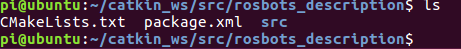
You can manually create a folder, but you will also have to manually write two more files that ROS works with: CMakeLists.txt and package.xml.
They are present in the folder after creation:
Their ROS creates on their own. While we will not dwell on their contents.
rospy at the end of the command means creating dependencies, python support.
Moving on.
Inside the newly created rosbots_description package, create the urdf folder, and in it the rosbots.xacro file.
The beauty of the ROS system is that in which system folder you would not be located, you can immediately get to the target by simply typing its name with the roscd command at the beginning of the line.
Now put the following code in the newly created file:
If the code does not appear, then all files can be downloaded at the end of the post.
For the code above, we also need cells (meches), which will be loaded during the launch of the package.
Meches can be taken here
and put the unpacked meches folder in rosbots_description.
If you look at the code in detail, you can find out that this is a standard xml file consisting of blocks:
- visual
- collision
- inertial
Each block describes its part: visual is the appearance of the robot, no more, collision and inertial is the physics of the robot, how everything will interact with the outside world - collisions, inertia.
joints - elements that help determine the movement between parts of the robot (links). For example, the movement of the wheel (wheel) affects the frame as a whole (chasis).
origin xyz - this is the initial location of the object along the x, y, z axes.
parent link and child link are the parent and child links, respectively, which grows out of what.
The presence of types is also noteworthy: type = "continuous", type = "fixed". It is a definition of what can and cannot rotate. So the wheels are continuous. And, for example, batery_joint is fixed.
Indentation in the code is as deeply meaningful as in python, where you can not interfere with tabs and spaces, do not carry. But for a perfectionist’s paradise and visibility it’s better to have them.
The code above is essentially a robot model.
Let's see what happened.
To do this, create a startup file that will run the ROS package.
For this, the so-called launch files are used in ROS. The essence of the launch file is to let the node, command, or several nodes run with one short command without the need to specify all arguments and other in it.
Create a launch folder in the rosbots_description with the rviz.launch file:
* This and subsequent times there is no longer a need to create a ROS package as it was done before. Now the system itself will “see” the files inside the package. Therefore, we just create a directory.
Fill the file with contents -
Here you can see that at startup the system will look for a model description in rosbots.xacro.
Next, it will launch 3 nodes: joint_state_publisher from the joint_state_publisher package, robot_state_publisher from robot_state_publisher, rviz from rviz. type is the type of node, which usually corresponds to the Python or C file of the same name, but is specified without an extension.
Run:
In the 1st terminal, run the ROS master:
In the 2nd:
* If an error occurred
specify the ip of the virtual machine in the bashrc file itself (for example, this one):
re-read bashrc further:
or reboot.
**
If roslaunch still does not start, then you can try to go to the catkin_ws folder and run: source devel / setup.bash
After the command is executed, the Rviz editor starts and the graphical shell opens.
The visual presentation may differ, but in general the view will be approximately as follows:
On the left in the Displays column, you can observe the display options for various elements interacting with ROS nodes, in the center - the image of the robot, on the right - a column with a camera view of the robot. I must say right away that it is better to work with rviz with a 3-wheel mouse, since all the mouse buttons are involved here. By holding the left, you can rotate the space in the window with the robot displayed, holding the right - zoom in / out, holding both keys - move the space relative to the robot.
Most of the work in the editor is carried out in the first two columns: Displays and the visual representation of the robot.
Let's select “Fixed Frame” - “base link” in the line:
And add Robot Description to Displays:
Click "Add" and select "RobotModel" in the list:
 "
"
Now in the simulation window you can observe the robot that was reproduced from the rviz.xacro model:
 "
"
Fine. With a visual representation, everything is clear. Now you need to understand how to run the simulation, because rviz is only a visualization of the simulation, but not the simulation itself.
That is, physics does not work here.
The simulation itself lives in an editor called Gazebo.
To place the created model in Gazebo, create another launch file - spawn.launch in the launch folder of the project. Now we have 2 launch files!
Here we also read the model, then with arguments we pass its location in space along the x, y, z axes. Next, run just one node - mybot_spawn from the gazebo_ros package.
* There is no need to reinstall the packages mentioned above. If desired, you can look at these packages with the same command: roscd. For example roscd gazebo_ros.
Now stop the Ros-master in terminal 1:
And run the Gazebo editor:
<sourceroslaunch gazebo_ros empty_world.launch
In the 2nd terminal, run the newly created file:
Now we see our robot in the simulation of the Gazebo editor:
* If you have a mistake:
This means that you launched the model without first starting Gazebo, violating the order of launch.
Now add the following code to rosbots.xacro before the closing tag:
Simulator Gazebo can not be closed when editing.
Now delete the model from the Gazebo editor:
Or just restart the editor.
* Gazebo is cranky in a virtual machine, so even after closing it sometimes forgive CTRL + C additionally in the terminal.
Re-place the model in Gazebo after editing:
If you now look at the list of ROS topics, you can see that among them there are
Now let's try to control the robot in the simulation by running control in a separate terminal:
Being in the window with the control running and pressing the keys “i”, “l”, “j”, “k”, “,” in the terminal window, you can observe the movement of the robot in the simulation of the Gazebo editor:
Code - download .
To be continued.
Previous posts in the series:
1. Part 3
2. Part 2
3. Part 1
Creating basic urdf files
In general, the process of creating a robot in a simplified manner usually consists of the following stages:
1. Creating a robot model.
2. Testing the model in a simulation.
3. Creating a real robot model.
4. Testing a real model.
When working with ROS editors, who provide great opportunities for both building models and their tests in the virtual world, we must admit that real robot models do not always behave like their incorporeal brothers. And here the time to work with models in the virtual world is added to the time necessary to finalize the real model.
Such a gift of time, as one famous person said, can not only afford everything.
In this regard, in previous posts the sequence of robotics was disrupted: first, a real model of the robot was created. Now we will talk about its virtualization, so to speak.
Create urdf
In order to fully enjoy the simulation in Gazebo and test the robot, you must first create a URDF file for the robot.
URDF file is a kind of skeleton skeleton in the field of visualization.
Simply put, a URDF file is a file describing a robot.
As previously stated, the work will be carried out using the VMWARE Workstation image on which ROS (Ubuntu 16.04, ROS-Kinetic) and visual editors are already installed. Therefore, all actions are reproducible in this system.
Create an ROS package called rosbots_description.
In order to do this, you need to enter the folder with catkin_ws / src and execute the command to create the package in ROS:
roscd; cd ..; cd src; catkin_create_pkg rosbots_description rospy
* If when executing the roscd command; cd ..; cd src; If you don’t get into catkin_ws, then maybe you have several environments of this type. In order to activate the necessary one, go to the catkin_ws folder and run the command: source devel / setup.bash. In order not to get lost, if you work with the image, you can get to this folder from the root: cd ~; cd catkin_ws.
If everything went well, the rosbots_description folder will be created.
Why is it so difficult and easier to just create a folder in catkin_ws / src manually? And what kind of rospy is it?
You can manually create a folder, but you will also have to manually write two more files that ROS works with: CMakeLists.txt and package.xml.
They are present in the folder after creation:
Their ROS creates on their own. While we will not dwell on their contents.
rospy at the end of the command means creating dependencies, python support.
Moving on.
Inside the newly created rosbots_description package, create the urdf folder, and in it the rosbots.xacro file.
roscd rosbots_description mkdir urdf; cd urdf; touch rosbots.xacro chmod +x rosbots.xacro
The beauty of the ROS system is that in which system folder you would not be located, you can immediately get to the target by simply typing its name with the roscd command at the beginning of the line.
Now put the following code in the newly created file:
rosbots.xacro
<?xml version="1.0" encoding="utf-8"?> <robot name="rosbots" xmlns:xacro="http://www.ros.org/wiki/xacro"> <link name="base_footprint"/> <joint name="base_joint" type="fixed"> <origin xyz="0 0 0.05" rpy="0 0 0" /> <parent link="base_footprint"/> <child link="base_link" /> </joint> <link name="base_link"> <visual> <geometry> <mesh filename="package://rosbots_description/meshes/base.dae"/> </geometry> <origin xyz="-0.52 -0.4 0.43" rpy="0 0 0"/> </visual> <collision> <geometry> <mesh filename="package://rosbots_description/meshes/base.dae"/> </geometry> <origin xyz="-0.52 -0.4 0.43" rpy="0 0 0"/> </collision> <inertial> <origin xyz="0.0 0 0."/> <mass value="0.5"/> <inertia ixx="0.01" ixy="0.0" ixz="0.0" iyy="0.01" iyz="0.0" izz="0.03" /> </inertial> </link> <joint name="second_level_joint" type="fixed"> <origin xyz="0 0 0.68" rpy="0 0 0" /> <parent link="base_link"/> <child link="base_second_link" /> </joint> <link name="base_second_link"> <visual> <geometry> <mesh filename="package://rosbots_description/meshes/base.dae"/> </geometry> <origin xyz="-0.52 -0.4 0.0" rpy="0 0 0"/> </visual> <collision> <geometry> <mesh filename="package://rosbots_description/meshes/base.dae"/> </geometry> <origin xyz="-0.52 -0.4 0.0" rpy="0 0 0"/> </collision> <!--inertial> <origin xyz="0.01 0 0.7"/> <mass value="1.0"/> <inertia ixx="0.01" ixy="0.0" ixz="0.0" iyy="0.01" iyz="0.0" izz="0.03" /> </inertial--> </link> <joint name="mcu_joint" type="fixed"> <origin xyz="0.02 0.12 0.73" rpy="0 0 0" /> <parent link="base_link"/> <child link="mcu_link" /> </joint> <link name="mcu_link"> <visual> <geometry> <mesh filename="package://rosbots_description/meshes/rasp.dae" scale="0.14 0.14 0.14"/> </geometry> <origin xyz="0.9 -1.25 0" rpy="0 0 1.57"/> </visual> <collision> <geometry> <mesh filename="package://rosbots_description/meshes/rasp.dae" scale="0.14 0.14 0.14"/> </geometry> <origin xyz="0.9 -1.25 0" rpy="0 0 1.57"/> </collision> <!-- inertial> <origin xyz="0.01 0 0"/> <mass value="1.0"/> <inertia ixx="0.019995" ixy="0.0" ixz="0.0" iyy="0.019995" iyz="0.0" izz="0.03675" /> </inertial--> </link> <joint name="mcu_joint_1" type="fixed"> <origin xyz="0.02 0.12 0.83" rpy="0 0 0" /> <parent link="base_link"/> <child link="mcu_link_1" /> </joint> <link name="mcu_link_1"> <visual> <geometry> <mesh filename="package://rosbots_description/meshes/rasp.dae" scale="0.14 0.14 0.14"/> </geometry> <origin xyz="0.9 -1.25 0" rpy="0 0 1.57"/> </visual> <collision> <geometry> <mesh filename="package://rosbots_description/meshes/rasp.dae" scale="0.14 0.14 0.14"/> </geometry> <origin xyz="0.9 -1.25 0" rpy="0 0 1.57"/> </collision> <!-- inertial> <origin xyz="0.01 0 0"/> <mass value="1.0"/> <inertia ixx="0.019995" ixy="0.0" ixz="0.0" iyy="0.019995" iyz="0.0" izz="0.03675" /> </inertial--> </link> <joint name="stand_mcu1_joint" type="fixed"> <origin xyz="0.02 0.25 0.78" rpy="0 0 1.57" /> <parent link="base_link"/> <child link="stand_mcu1_link" /> </joint> <link name="stand_mcu1_link"> <visual> <geometry> <cylinder length="0.1" radius="0.01"/> </geometry> <origin rpy="0.0 0 0" xyz="0 0 0.0"/> </visual> <collision> <geometry> <cylinder length="0.1" radius="0.01"/> </geometry> <origin rpy="0.0 0 0" xyz="0 0 0.0"/> </collision> </link> <joint name="stand_mcu2_joint" type="fixed"> <origin xyz="0.02 -0.1125 0.78" rpy="0 0 1.57" /> <parent link="base_link"/> <child link="stand_mcu2_link" /> </joint> <link name="stand_mcu2_link"> <visual> <geometry> <cylinder length="0.1" radius="0.01"/> </geometry> <origin rpy="0.0 0 0" xyz="0 0 0.0"/> </visual> <collision> <geometry> <cylinder length="0.1" radius="0.01"/> </geometry> <origin rpy="0.0 0 0" xyz="0 0 0.0"/> </collision> </link> <joint name="stand_mcu3_joint" type="fixed"> <origin xyz="0.25 0.25 0.78" rpy="0 0 1.57" /> <parent link="base_link"/> <child link="stand_mcu3_link" /> </joint> <link name="stand_mcu3_link"> <visual> <geometry> <cylinder length="0.1" radius="0.01"/> </geometry> <origin rpy="0.0 0 0" xyz="0 0 0.0"/> </visual> <collision> <geometry> <cylinder length="0.1" radius="0.01"/> </geometry> <origin rpy="0.0 0 0" xyz="0 0 0.0"/> </collision> </link> <joint name="stand_mcu4_joint" type="fixed"> <origin xyz="0.25 -0.1125 0.78" rpy="0 0 1.57" /> <parent link="base_link"/> <child link="stand_mcu4_link" /> </joint> <link name="stand_mcu4_link"> <visual> <geometry> <cylinder length="0.1" radius="0.01"/> </geometry> <origin rpy="0.0 0 0" xyz="0 0 0.0"/> </visual> <collision> <geometry> <cylinder length="0.1" radius="0.01"/> </geometry> <origin rpy="0.0 0 0" xyz="0 0 0.0"/> </collision> </link> <joint name="batery_joint" type="fixed"> <origin xyz="1.2 0.2 0.43" rpy="0 0 1.57" /> <parent link="base_link"/> <child link="batery_link" /> </joint> <link name="batery_link"> <visual> <geometry> <mesh filename="package://rosbots_description/meshes/battery.dae" scale="13.0 6.0 6.0"/> </geometry> <origin xyz="0 4.5 0.05" rpy="1.57 0 1.57"/> </visual> <collision> <geometry> <mesh filename="package://rosbots_description/meshes/battery.dae" scale="13.0 6.0 6.0"/> </geometry> <origin xyz="0 4.5 0.05" rpy="1.57 0 1.57"/> </collision> <!-- inertial> <origin xyz="0.01 0 0"/> <mass value="1.0"/> <inertia ixx="0.01" ixy="0.0" ixz="0.0" iyy="0.01" iyz="0.0" izz="0.03" /> </inertial--> </link> <joint name="stand_1_joint" type="fixed"> <origin xyz="0.5 0.4125 0.58" rpy="0 0 1.57" /> <parent link="base_link"/> <child link="stand_1_link" /> </joint> <link name="stand_1_link"> <visual> <geometry> <cylinder length="0.20" radius="0.03"/> </geometry> <origin rpy="0.0 0 0" xyz="0 0 0.0"/> </visual> <collision> <geometry> <cylinder length="0.20" radius="0.03"/> </geometry> <origin rpy="0.0 0 0" xyz="0 0 0.0"/> </collision> <!--inertial> <origin xyz="0.0 0 0"/> <mass value="1.0"/> <inertia ixx="0.019995" ixy="0.0" ixz="0.0" iyy="0.019995" iyz="0.0" izz="0.03675" /> </inertial--> </link> <joint name="stand_2_joint" type="fixed"> <origin xyz="0.5 -0.2625 0.58" rpy="0 0 1.57" /> <parent link="base_link"/> <child link="stand_2_link" /> </joint> <link name="stand_2_link"> <visual> <geometry> <cylinder length="0.20" radius="0.03"/> </geometry> <origin rpy="0.0 0 0" xyz="0 0 0.0"/> </visual> <collision> <geometry> <cylinder length="0.20" radius="0.03"/> </geometry> <origin rpy="0.0 0 0" xyz="0 0 0.0"/> </collision> <!--inertial> <origin xyz="0.0 0 0"/> <mass value="1.0"/> <inertia ixx="0.019995" ixy="0.0" ixz="0.0" iyy="0.019995" iyz="0.0" izz="0.03675" /> </inertial--> </link> <joint name="wheel_left_joint" type="continuous"> <parent link="base_link"/> <child link="wheel_left_link"/> <origin xyz="0.15 0.4125 0.30" rpy="-1.57 0 0"/> <axis xyz="0 0 1"/> </joint> <link name="wheel_left_link"> <collision> <geometry> <cylinder length="0.20" radius="0.23"/> </geometry> <origin rpy="0.0 0.0 0" xyz="0 0 0.1"/> </collision> <visual name="visual"> <geometry> <!-- cylinder length="0.0206" radius="0.0550"/--> <!--cylinder length="0.20" radius="0.26"/--> <mesh filename="package://rosbots_description/meshes/wheel.dae" scale="8.0 8.0 8.0"/> </geometry> <origin rpy="0.0 0 0" xyz="0 0 0"/> </visual> <inertial> <mass value="0.4" /> <origin xyz="0 0 0" /> <inertia ixx="0.001" ixy="0.0" ixz="0.0" iyy="0.001" iyz="0.0" izz="0.001" /> </inertial> </link> <joint name="wheel_right_joint" type="continuous"> <parent link="base_link"/> <child link="wheel_right_link"/> <origin xyz="0.15 -0.5625 0.30" rpy="-1.57 0 0"/> <axis xyz="0 0 1"/> </joint> <link name="wheel_right_link"> <collision> <geometry> <cylinder length="0.20" radius="0.23"/> </geometry> <origin rpy="0.0 0 0" xyz="0 0 0.195"/> </collision> <visual name="visual"> <geometry> <!--cylinder length="0.20" radius="0.26"/--> <mesh filename="package://rosbots_description/meshes/wheel.dae" scale="8.0 8.0 8.0"/> </geometry> <origin rpy="0.0 0 0" xyz="0 0 0"/> </visual> <inertial> <mass value="0.4" /> <origin xyz="0 0.0 0.3" /> <inertia ixx="0.001" ixy="0.0" ixz="0.0" iyy="0.001" iyz="0.0" izz="0.001" /> </inertial> </link> <joint name="caster_back_joint" type="fixed"> <parent link="base_link"/> <child link="caster_back_link"/> <origin xyz="-0.4 0.1 0.26" rpy="0 0 0"/> </joint> <link name="caster_back_link"> <collision> <geometry> <!-- cylinder length="0.05" radius="0.19"/--> <sphere radius="0.19"/> </geometry> <origin rpy="0 0 0" xyz="0 0 0"/> </collision> <visual> <geometry> <!--cylinder length="0.05" radius="0.19"/--> <sphere radius="0.19"/> </geometry> <origin rpy="0 0 0" xyz="0 0 0"/> </visual> <inertial> <mass value="0.1" /> <origin xyz="0 0 0" /> <inertia ixx="0.001023539" ixy="0.0" ixz="0.0" iyy="0.001023539" iyz="0.0" izz="0.001023539" /> </inertial> </link> <joint name="stand_3_joint" type="fixed"> <origin xyz="-0.4 0.4125 0.58" rpy="0 0 1.57" /> <parent link="base_link"/> <child link="stand_3_link" /> </joint> <link name="stand_3_link"> <visual> <geometry> <cylinder length="0.20" radius="0.03"/> </geometry> <origin rpy="0.0 0 0" xyz="0 0 0.0"/> </visual> <collision> <geometry> <cylinder length="0.20" radius="0.03"/> </geometry> <origin rpy="0.0 0 0" xyz="0 0 0.0"/> </collision> </link> <joint name="stand_4_joint" type="fixed"> <origin xyz="-0.4 -0.2625 0.58" rpy="0 0 1.57" /> <parent link="base_link"/> <child link="stand_4_link" /> </joint> <link name="stand_4_link"> <visual> <geometry> <cylinder length="0.20" radius="0.03"/> </geometry> <origin rpy="0.0 0 0" xyz="0 0 0.0"/> </visual> <collision> <geometry> <cylinder length="0.20" radius="0.03"/> </geometry> <origin rpy="0.0 0 0" xyz="0 0 0.0"/> </collision> </link> </robot>
If the code does not appear, then all files can be downloaded at the end of the post.
For the code above, we also need cells (meches), which will be loaded during the launch of the package.
Meches can be taken here
and put the unpacked meches folder in rosbots_description.
If you look at the code in detail, you can find out that this is a standard xml file consisting of blocks:
- visual
- collision
- inertial
Each block describes its part: visual is the appearance of the robot, no more, collision and inertial is the physics of the robot, how everything will interact with the outside world - collisions, inertia.
joints - elements that help determine the movement between parts of the robot (links). For example, the movement of the wheel (wheel) affects the frame as a whole (chasis).
origin xyz - this is the initial location of the object along the x, y, z axes.
parent link and child link are the parent and child links, respectively, which grows out of what.
The presence of types is also noteworthy: type = "continuous", type = "fixed". It is a definition of what can and cannot rotate. So the wheels are continuous. And, for example, batery_joint is fixed.
Indentation in the code is as deeply meaningful as in python, where you can not interfere with tabs and spaces, do not carry. But for a perfectionist’s paradise and visibility it’s better to have them.
The code above is essentially a robot model.
Work at rviz
Let's see what happened.
To do this, create a startup file that will run the ROS package.
For this, the so-called launch files are used in ROS. The essence of the launch file is to let the node, command, or several nodes run with one short command without the need to specify all arguments and other in it.
Create a launch folder in the rosbots_description with the rviz.launch file:
roscd rosbots_description mkdir launch; cd launch; touch rviz.launch
* This and subsequent times there is no longer a need to create a ROS package as it was done before. Now the system itself will “see” the files inside the package. Therefore, we just create a directory.
Fill the file with contents -
rviz.launch
<?xml version="1.0"?> <launch> <param name="robot_description" command="cat '$(find rosbots_description)/urdf/rosbots.xacro'"/> <!-- send fake joint values --> <node name="joint_state_publisher" pkg="joint_state_publisher" type="joint_state_publisher"> <param name="use_gui" value="False"/> </node> <!-- Combine joint values --> <node name="robot_state_publisher" pkg="robot_state_publisher" type="state_publisher"/> <!-- Show in Rviz --> <node name="rviz" pkg="rviz" type="rviz" /> </launch>
Here you can see that at startup the system will look for a model description in rosbots.xacro.
Next, it will launch 3 nodes: joint_state_publisher from the joint_state_publisher package, robot_state_publisher from robot_state_publisher, rviz from rviz. type is the type of node, which usually corresponds to the Python or C file of the same name, but is specified without an extension.
Run:
In the 1st terminal, run the ROS master:
roscore
In the 2nd:
roslaunch rosbots_description rviz.launch
* If an error occurred
ROS_MASTER_URI [http: //192.168.1 ....: 11311] host is not set to this machine, then you need to check bashrc - on which ip ROS is running:
nano ~/.bashrc
specify the ip of the virtual machine in the bashrc file itself (for example, this one):
export ROS_MASTER_URI=http://192.168.1.114:11311
re-read bashrc further:
source ~/.bashrc
or reboot.
**
If roslaunch still does not start, then you can try to go to the catkin_ws folder and run: source devel / setup.bash
Diving into Rviz
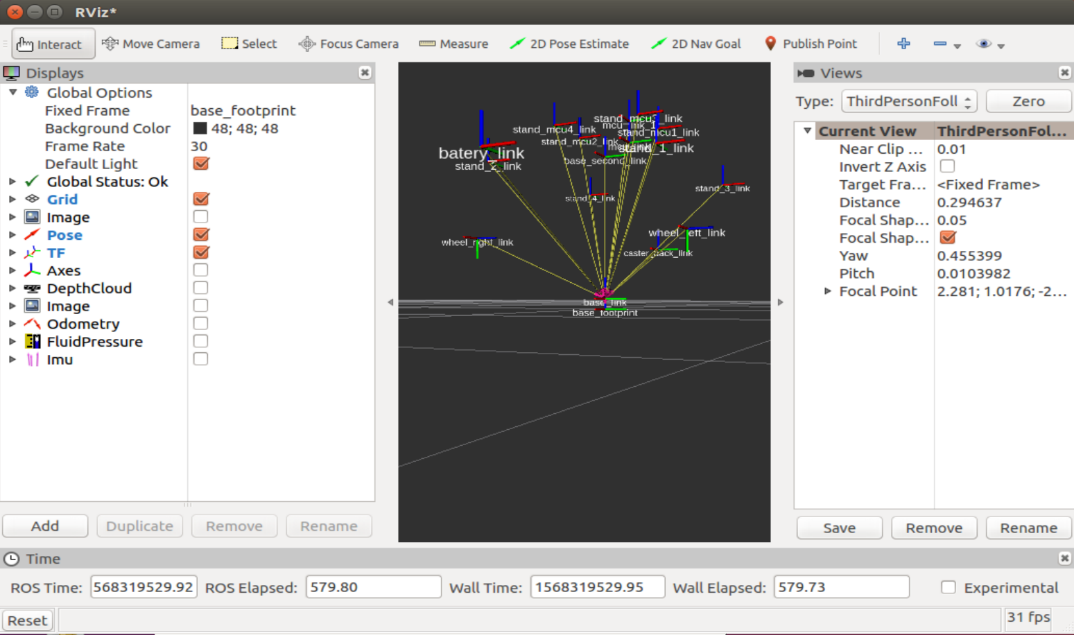
After the command is executed, the Rviz editor starts and the graphical shell opens.
The visual presentation may differ, but in general the view will be approximately as follows:
On the left in the Displays column, you can observe the display options for various elements interacting with ROS nodes, in the center - the image of the robot, on the right - a column with a camera view of the robot. I must say right away that it is better to work with rviz with a 3-wheel mouse, since all the mouse buttons are involved here. By holding the left, you can rotate the space in the window with the robot displayed, holding the right - zoom in / out, holding both keys - move the space relative to the robot.
Most of the work in the editor is carried out in the first two columns: Displays and the visual representation of the robot.
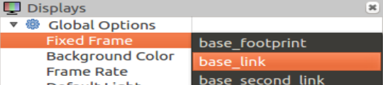
Let's work with the look of a robot
Let's select “Fixed Frame” - “base link” in the line:
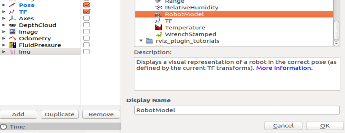
And add Robot Description to Displays:
Click "Add" and select "RobotModel" in the list:
"
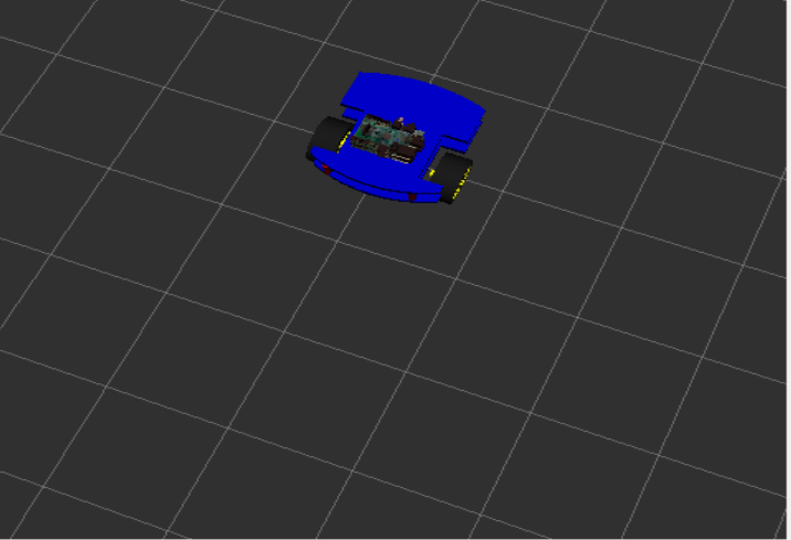
Now in the simulation window you can observe the robot that was reproduced from the rviz.xacro model:
"
Fine. With a visual representation, everything is clear. Now you need to understand how to run the simulation, because rviz is only a visualization of the simulation, but not the simulation itself.
That is, physics does not work here.
The simulation itself lives in an editor called Gazebo.
Gazebo
To place the created model in Gazebo, create another launch file - spawn.launch in the launch folder of the project. Now we have 2 launch files!
spawn.launch
<?xml version="1.0" encoding="UTF-8"?> <launch> <param name="robot_description" command="cat '$(find rosbots_description)/urdf/rosbots.xacro'" /> <arg name="x" default="0"/> <arg name="y" default="0"/> <arg name="z" default="0.5"/> <node name="mybot_spawn" pkg="gazebo_ros" type="spawn_model" output="screen" args="-urdf -param robot_description -model rosbots -x $(arg x) -y $(arg y) -z $(arg z)" /> </launch>
Here we also read the model, then with arguments we pass its location in space along the x, y, z axes. Next, run just one node - mybot_spawn from the gazebo_ros package.
* There is no need to reinstall the packages mentioned above. If desired, you can look at these packages with the same command: roscd. For example roscd gazebo_ros.
Now stop the Ros-master in terminal 1:
CTRL+C
And run the Gazebo editor:
<sourceroslaunch gazebo_ros empty_world.launch
In the 2nd terminal, run the newly created file:
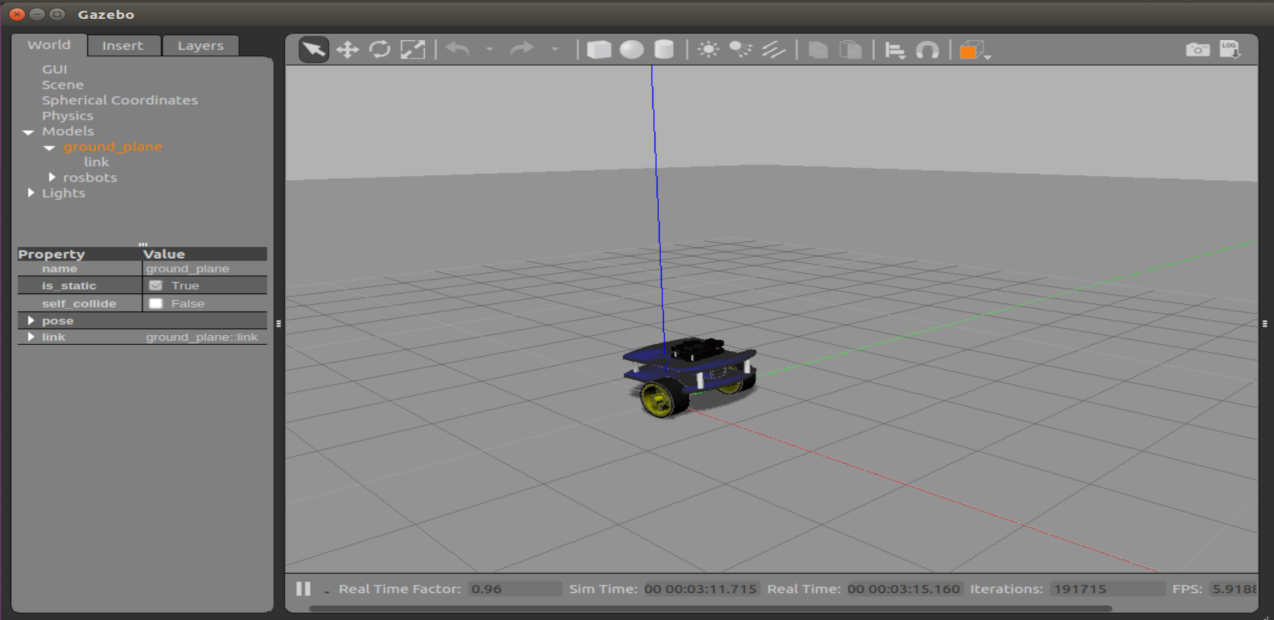
roslaunch rosbots_description spawn.launch
Now we see our robot in the simulation of the Gazebo editor:
* If you have a mistake:
Waiting for service /gazebo/spawn_urdf_model
This means that you launched the model without first starting Gazebo, violating the order of launch.
Let's go to the gazebo simulation.
Now add the following code to rosbots.xacro before the closing tag:
the code
<gazebo> <plugin name="differential_drive_controller" filename="libgazebo_ros_diff_drive.so"> <legacyMode>false</legacyMode> <alwaysOn>true</alwaysOn> <publishWheelTF>true</publishWheelTF> <publishTf>1</publishTf> <publishWheelJointState>true</publishWheelJointState> <updateRate>100.0</updateRate> <leftJoint>wheel_left_joint</leftJoint> <rightJoint>wheel_right_joint</rightJoint> <wheelSeparation>1.1</wheelSeparation> <wheelDiameter>0.52</wheelDiameter> <wheelAcceleration>1.0</wheelAcceleration> <torque>20</torque> <commandTopic>/part2_cmr/cmd_vel</commandTopic> <odometryTopic>odom</odometryTopic> <odometryFrame>odom</odometryFrame> <robotBaseFrame>base_link</robotBaseFrame> </plugin> </gazebo>
Simulator Gazebo can not be closed when editing.
Now delete the model from the Gazebo editor:
rosservice call /gazebo/delete_model "model_name: 'rosbots'"
Or just restart the editor.
* Gazebo is cranky in a virtual machine, so even after closing it sometimes forgive CTRL + C additionally in the terminal.
Re-place the model in Gazebo after editing:
roslaunch rosbots_description spawn.launch
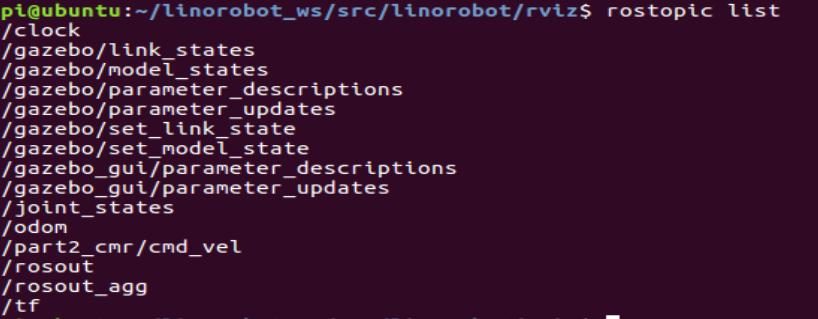
If you now look at the list of ROS topics, you can see that among them there are
/part2_cmr/cmd_vel
Now let's try to control the robot in the simulation by running control in a separate terminal:
rosrun teleop_twist_keyboard teleop_twist_keyboard.py /cmd_vel:=/part2_cmr/cmd_vel
Being in the window with the control running and pressing the keys “i”, “l”, “j”, “k”, “,” in the terminal window, you can observe the movement of the robot in the simulation of the Gazebo editor:
Code - download .
To be continued.
All Articles