Cloud Smart Home. Part 1: Controller and Sensors
Today, thanks to the rapid development of microelectronics, communication channels, Internet technologies and Artificial Intelligence, the topic of smart homes is becoming more and more relevant. The human dwelling has undergone significant changes since the Stone Age and in the era of the Industrial Revolution 4.0 and the Internet of Things became convenient, functional and safe. Solutions come to the market that turn an apartment or a country house into sophisticated information systems managed from anywhere in the world using a smartphone. Moreover, knowledge of programming languages is no longer required for human-machine interaction - thanks to the speech recognition and speech synthesis algorithms, a person speaks his native language with a smart home.
Some smart home systems currently on the market are a logical development of cloud-based video surveillance systems, the developers of which realized the need for a comprehensive solution not only for monitoring, but also for managing remote objects.
We offer you a series of three articles, which will tell you about all the main components of the cloud smart home system, personally developed by the author and put into operation. The first article is devoted to terminal client equipment installed inside a smart home, the second to the architecture of a cloud storage and data processing system, and finally, the third to a client application for managing the system on mobile and stationary devices.
Smart Home Equipment
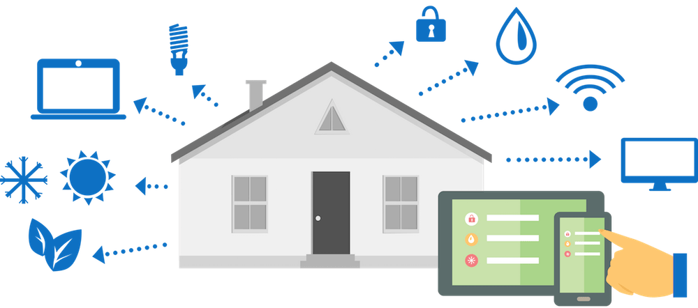
First, let's talk about how to make a smart home out of an ordinary apartment, cottage or cottage. For this, as a rule, it is required to place the following equipment in the home:
- sensors measuring various environmental parameters;
- actuators acting on external objects;
- a controller that performs calculations in accordance with sensor measurements and embedded logic, and issues commands to actuators.
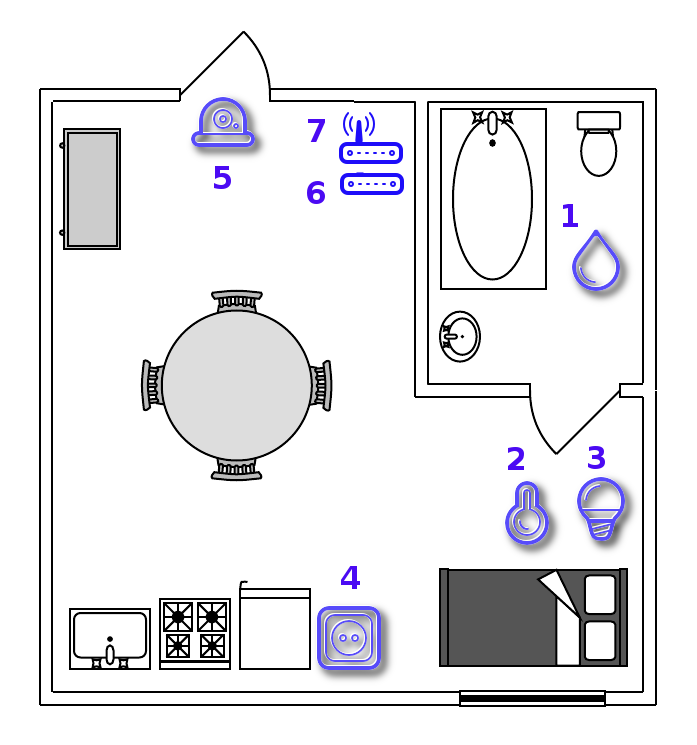
The following figure shows the diagram of a smart home, on which there are sensors for water leakage (1) in the bathroom, temperature (2) and lighting (3) in the bedroom, a smart socket (4) in the kitchen and a video surveillance camera (5) in the hallway.
Currently, wireless sensors operating under the protocols RF433, Z-Wave, ZigBee, Bluetooth and WiFi are widely used. Their main advantages are ease of installation and use, as well as low cost and reliability, because Manufacturers seek to bring their devices to the mass market and make them available to the average user.
Sensors and actuators are usually connected via a wireless interface to the smart home controller (6) - a specialized microcomputer that integrates all these devices into a single network and controls them.
However, some solutions can combine a sensor, an actuator and a controller at the same time. For example, a smart socket can be programmed to turn on or off on a schedule, and a cloud-based video surveillance camera can record video based on a motion detector signal. In the simplest cases, you can do without a separate controller, but to create a flexible system with many scenarios, it is necessary.
To connect the smart home controller to the global network, a conventional Internet router (7) can be used, which has long been a familiar household appliance in any home. There is one more argument in favor of the smart home controller - if the connection to the Internet is lost, the smart home will continue to operate normally due to the logic block stored inside the controller, and not in the cloud service.
Smart home controller
The controller for the cloud smart home system discussed in this article was developed on the basis of the Raspberry Pi 3 model B + single-board microcomputer, which was released in March 2018 and has sufficient resources and performance for smart home tasks. It consists of a four-core Cortex-A53 processor with a 64-bit ARMv8-A architecture, with a clock frequency of 1.4 GHz, as well as 1 GB of RAM, Wi-Fi 802.11ac, Bluetooth 4.2 and a gigabit Ethernet adapter working via the USB 2.0 bus.
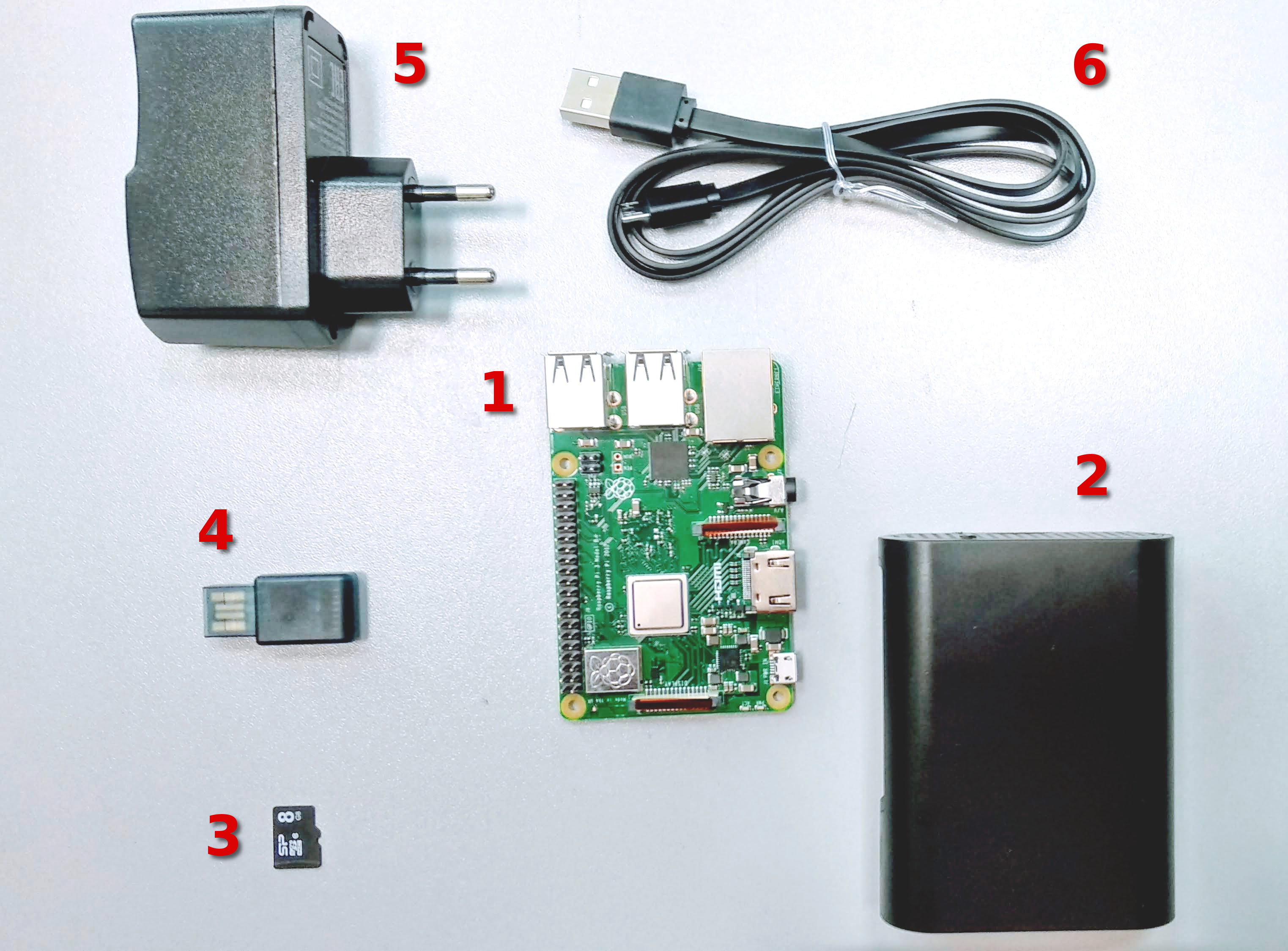
Assembly of the controller is very simple - the microcomputer (1) is installed in a plastic case (2), then an 8 GB microSD card with software (3) and a USB Z-Wave network controller (4) are inserted into the corresponding slots in it. The smart home controller is connected to the mains via a 5V, 2.1A (5) power adapter and a micro-USB cable (6). Each controller has a unique identification number, which is recorded in the configuration file at the first start and is necessary for interaction with cloud smart home services.
Smart home controller software was developed by the author of this article based on the Linux Raspbian Stretch operating system. It consists of the following main subsystems:
- server process for interacting with smart home equipment and the cloud;
- graphical user interface for configuring the controller and operating parameters;
- Databases for storing the controller configuration.
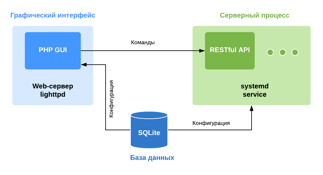
The database of the smart home controller is based on the embedded SQLite DBMS and is a file on the SD card with system software. It serves as a repository of the controller configuration - information about the connected equipment and its current state, a block of logical production rules, as well as information requiring indexing (for example, file names of the local video archive). When the controller is rebooted, this information is saved, which makes it possible to restore the controller's operability in the event of power failure.
The graphical interface of the smart home controller is developed in PHP 7 using the Slim microframework. The lighttpd web server, which is often used in embedded devices due to its good performance and low resource requirements, is responsible for the operation of the application.
(click on the picture to open in higher resolution)
The main function of the graphical interface is to connect smart home equipment (IP-cameras and sensors) to the controller. The web application reads the configuration and current status of the controller and devices connected to it from the SQLite database. To change the configuration of the controller, it sends control commands in JSON format through the RESTful API of the server process.
Server process
The server process is a key component that does all the basic work of automating the information processes that make up the foundation of a smart home: receiving and processing sensory data, issuing control actions depending on the logic in place. The purpose of the server process is to interact with smart home equipment, follow production logic rules, receive and process commands from the graphical interface and the cloud. The server process in this smart home controller is implemented as a multi-threaded application developed in C ++ and launched as a separate systemd service of the Linux Raspbian operating system.
The main blocks of the server process are:
- Message Manager
- IP camera server;
- Z-Wave device server;
- Server production logic rules;
- Database of controller configuration and block of logical rules;
- RESTful API server for interacting with the graphical interface;
- MQTT client for interacting with the cloud.
The blocks of the server process are implemented as separate streams, the information between which is transmitted in the form of messages in the JSON format (or data structures representing this format in the process memory).
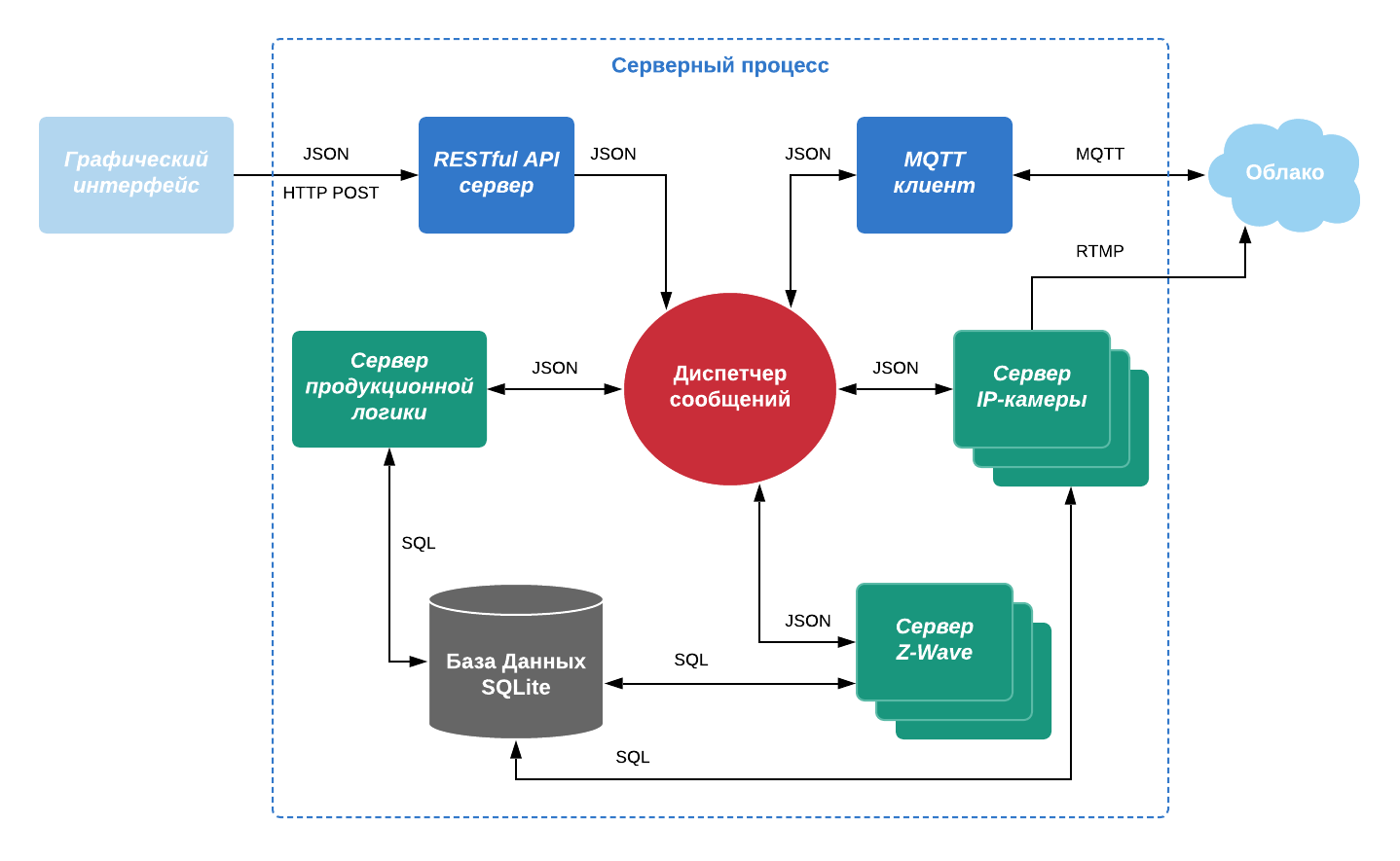
The main component of the server process is the message manager , which routes JSON messages to all blocks of the server process. The types of JSON message information fields and the values that they can accept are listed in the table:
| deviceType | protocol | messageType | deviceState | command |
|---|---|---|---|---|
| camera | onvif | sensorData | on | streaming (On / Off) |
| sensor | zwave | command | off | recording (On / Off) |
| effector | mqtt | businessLogicRule | streaming (On / Off) | evice (Add / Remove) |
| businesslogic | configurationData | recording (On / Off) | ||
| bluetooth | deviceState | error | ||
| wifi | ||||
| rf |
For example, a message from a camera motion detector looks like this:
{ "vendor": "*****", "version": "3.0.0", "timestampMs": "1566293475475", "clientType": "gateway", "deviceId": "1616453d-30cd-44b7-9bf0-************", "deviceType": "camera", "protocol": "onvif", "messageType": "sensorData", "sensorType": "camera", "label": "motionDetector", "sensorData": "on" }
Production logic
To receive or send a message from the dispatcher, the server process block subscribes to messages of a certain type. Subscription is a production logical rule of the type "If ... then ..." , presented in JSON format, and a link to the message handler inside the server process unit. For example, so that the IP camera server can receive commands from the GUI and the cloud, you need to add the following rule:
{ "if": { "and": [{ "equal": { "deviceId": "1616453d-30cd-44b7-9bf0-************" } }, { "equal": { "messageType": "command" } } ] }, "then": { "result": "true" } }
If the conditions indicated in the antecedent (left side) of the rule are true, then the rule (right side) of the rule is executed, and the handler gets access to the body of the JSON message. The antecedent supports logical operators that perform comparison of JSON key-value pairs:
- equal to "equal";
- not equal to "not_equal";
- less "less";
- more "greater";
- less than or equal to "less_or_equal";
- greater than or equal to greater_or_equal.
The comparison results can be linked together using the operators of Boolean algebra:
- And "and";
- OR "or";
- NOT "not".
Thus, writing operators and operands in Polish notation, it is possible to form fairly complex conditions with a large number of parameters.
Exactly the same mechanism, based on JSON messages and production rules in JSON format, is used in the production logic server block to represent knowledge and make logical inference using sensory data from smart home sensors.
Using a mobile application, a user makes scripts according to which a smart home should function. For example: "If the sensor for opening the front door has worked, then turn on the light in the hallway . " The application reads the identifiers of sensors (opening sensor) and actuators (smart socket or smart lamp) from the database and generates a logical rule in JSON format, which is sent to the smart home controller. This mechanism will be discussed in more detail in the third article of our series, where we will talk about a client application for managing a smart home.
The production logic mechanism discussed above is implemented using the RapidJSON library, a SAX parser of the JSON format in C ++. Sequential reading and parsing an array of production rules makes it easy to implement the data matching function within antecedents:
void CRuleEngine::Process(PProperties pFact) { m_pActions->clear(); rapidjson::Reader reader; for(TStringMap::value_type& rRule : m_Rules) { std::string sRuleId = rRule.first; std::string sRuleBody = rRule.second; CRuleHandler ruleHandler(pFact); rapidjson::StringStream ruleStream(sRuleBody.c_str()); rapidjson::ParseResult parseResult = reader.Parse(ruleStream, ruleHandler); if(!parseResult) { m_Logger.LogMessage( NLogger2::ePriorityLevelError, std::string("JSON parse error"), "CRuleEngine::Process()", std::string("RuleId: ") + sRuleId); } PProperties pAction = ruleHandler.GetAction(); if(pAction) { pAction->Set("ruleId", sRuleId); m_pActions->push_back(pAction); } } }
Here pFact is a structure containing key-value pairs from a JSON message, m_Rules is a string array of production rules. Comparison of the incoming message and production rules is performed in the reader.Parse (ruleStream, ruleHandler) function , where ruleHandler is an object containing the logic of Boolean operators and comparison operators. sRuleId is a unique rule identifier, thanks to which it is possible to store and edit rules inside the database of a smart home controller. m_pActions - an array with the results of logical inference: JSON messages containing consistents from the rule base and forwarded to the message manager so that subscriber streams can process them.
The performance of RapidJSON is comparable to the strlen () function, and the minimum system resource requirements allow you to use this library in embedded devices. Using messages and logical rules in JSON format allows you to implement a flexible system of information exchange between all components of the smart home controller.
Sensors and Actuators Z-Wave
The main advantage of a smart home is that it can independently measure various environmental parameters and perform useful functions depending on the situation. To do this, sensors and actuators are connected to the smart home controller. In the current version, these are wireless devices operating according to the Z-Wave protocol at a specially allocated frequency of 869 MHz for Russia. For their work, they are combined into a mesh network in which signal repeaters are present to increase the coverage area. The devices also have a special energy-saving mode - they spend most of the time in sleep mode and send information only when their state changes, which can significantly extend the life of the built-in battery.
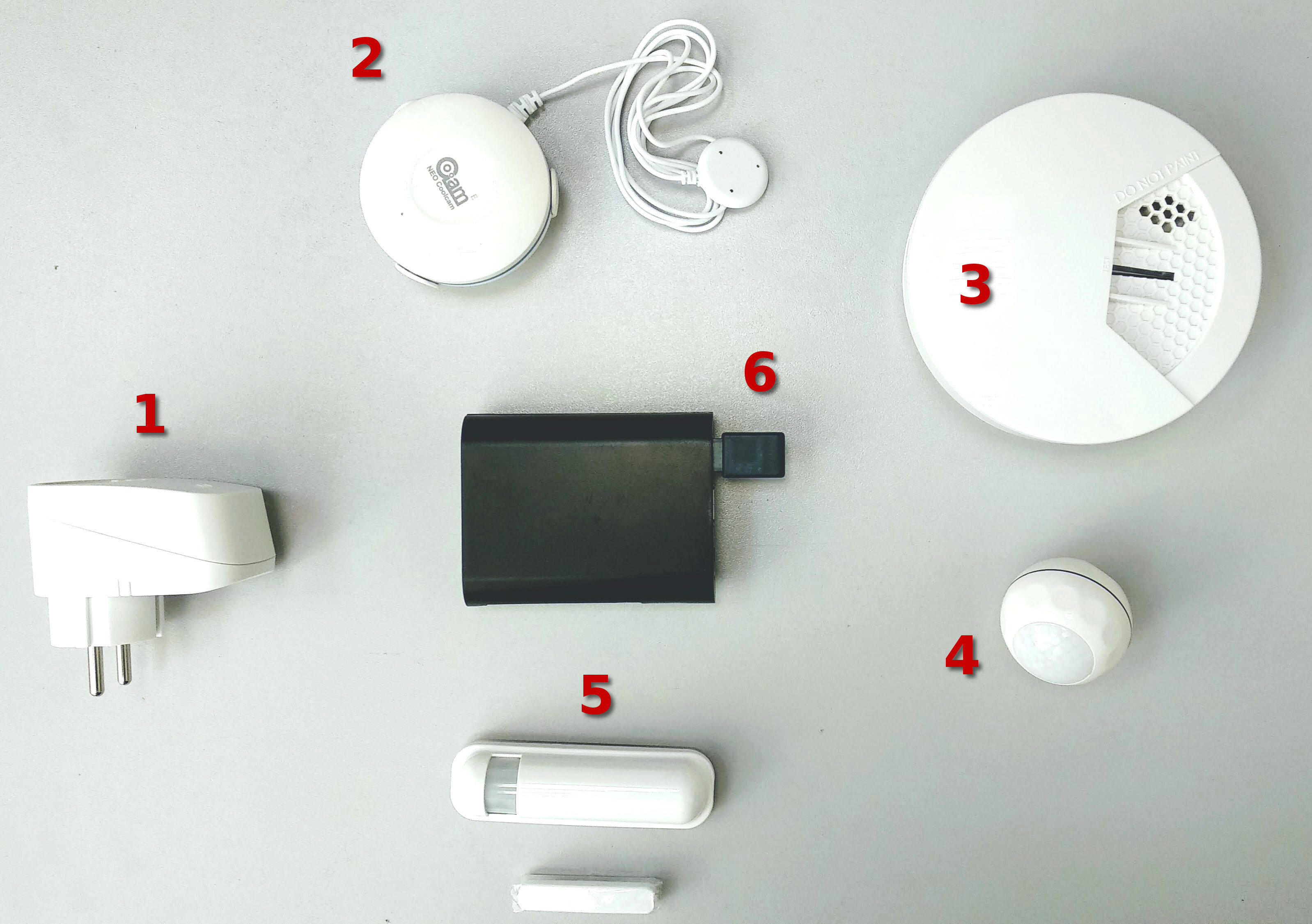
On the market now you can find a fairly large number of different Z-Wave devices. As an example, consider a few:
- Zipato PAN16 smart socket can measure the following parameters: power consumption (kW / h), power (W), voltage (V) and current (A) in the mains. It also has a built-in switch with which you can control the connected electrical appliance;
- The Neo Coolcam leakage sensor detects the presence of spilled liquid by closing the contacts of the remote probe;
- Zipato PH-PSG01 smoke detector is triggered when smoke particles enter the gas analyzer chamber;
- The Neo Coolcam motion sensor analyzes infrared radiation from a person’s body. Additionally there is a light sensor (Lx);
- The Philio PST02-A multisensor measures temperature (° C), light exposure (%), door opening, the presence of a person in the room;
- Z-Wave USB Stick ZME E UZB1 network controller, to which the sensors are connected.
It is very important that the devices and the controller work at the same frequency, otherwise they, simply, will not see each other at the time of connection. Up to 232 devices can be connected to one Z-Wave network controller, which is quite enough for an apartment or a country house. To expand the coverage area of the network indoors, a smart socket can be used as a signal repeater.
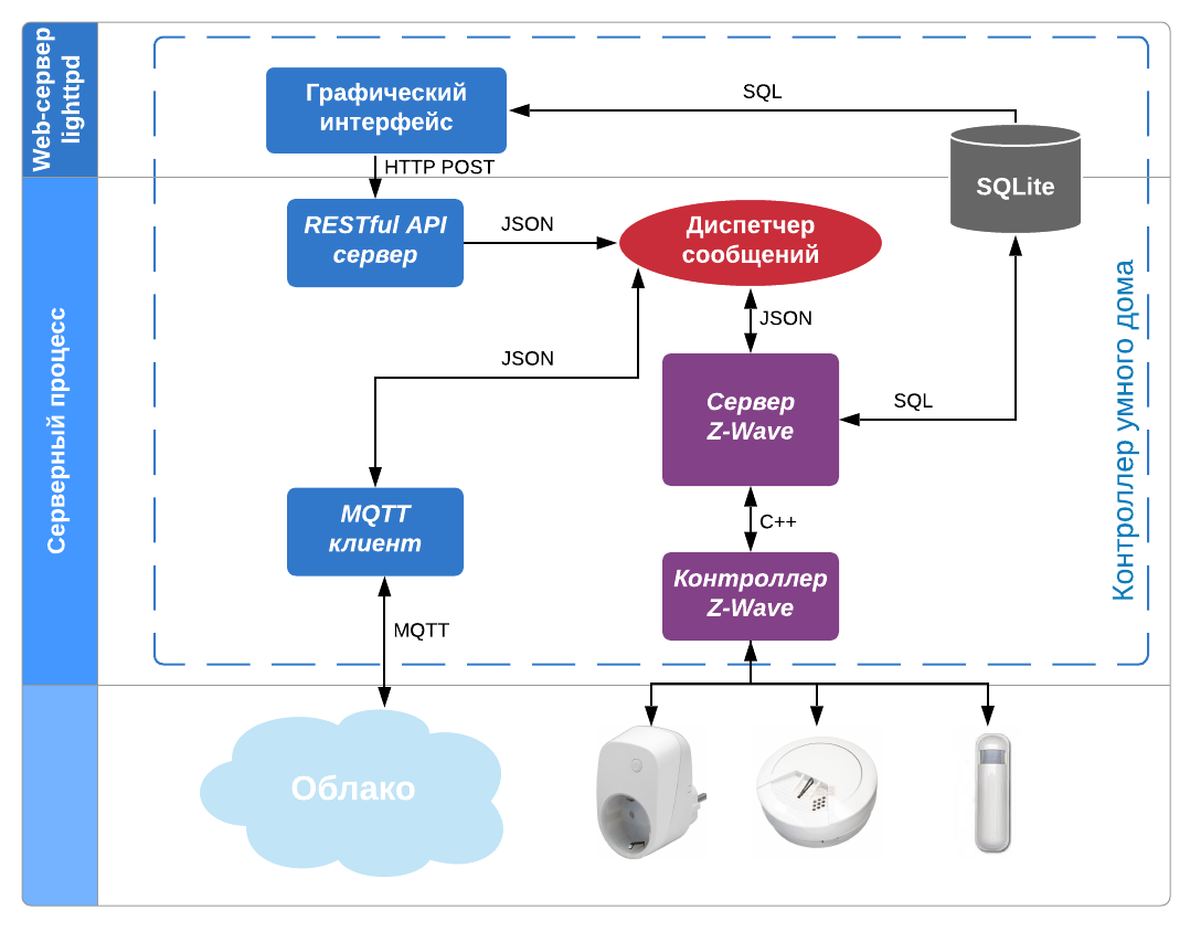
In the server process of the smart home controller, discussed in the previous paragraph, the Z-Wave server is responsible for interacting with Z-Wave devices. To obtain information from sensors, he uses the OpenZWave library in C ++, which provides an interface for interaction with a USB controller of the Z-Wave network and works with many sensors and actuators. The value of the environmental parameter measured by the sensor is recorded by the Z-Wave server in the form of a JSON message:
{ "vendor": "*****", "version": "3.0.0", "timestampMs": "1566479791290", "clientType": "gateway", "deviceId": "20873eb0-dd5e-4213-a175-************", "deviceType": "sensor", "protocol": "zwave", "messageType": "sensorData", "homeId": "0xefa0cfa7", "nodeId": "20", "sensorType": "METER", "label": "Voltage", "sensorData": "229.3", "units": "V" }
It is then forwarded to the server process message manager so that subscriber threads can receive it. The main subscriber is the production logic server, which compares the values of message fields in the antecedents of logical rules. The inference results containing control commands are sent back to the message manager and from there they go to the Z-Wave server, which decodes them and sends them to the Z-Wave network's USB controller. Then they fall into the executive device, which changes the state of the environment, and the smart home, thus, does a useful job.
(click on the picture to open in higher resolution)
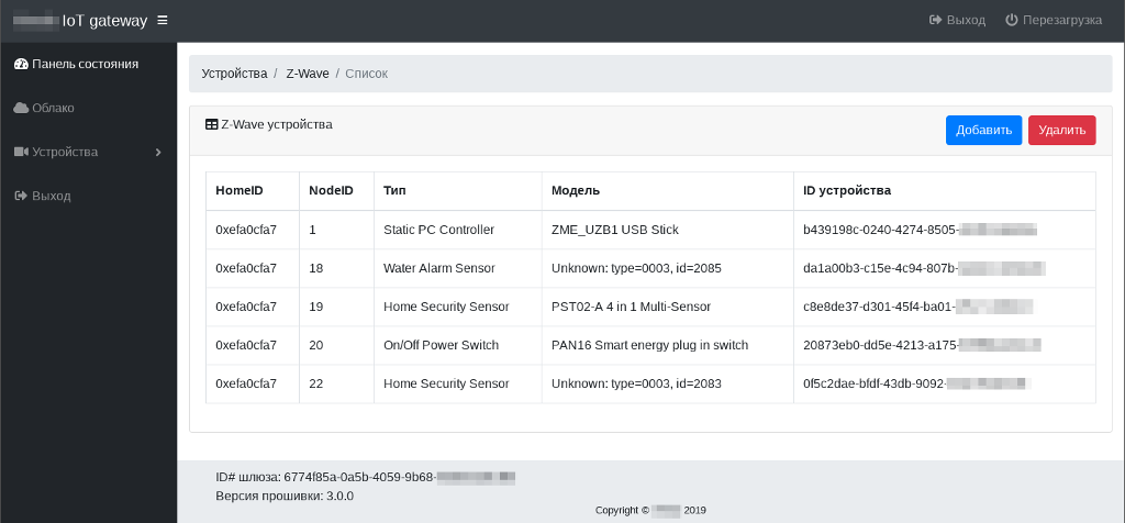
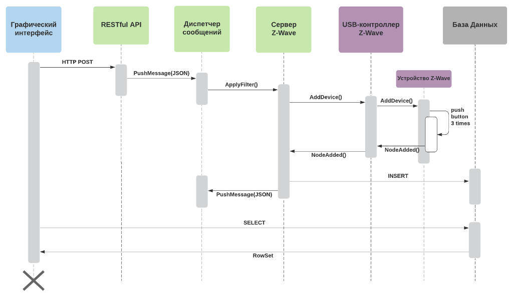
Z-Wave devices are connected in the graphical interface of the smart home controller. To do this, go to the page with the list of devices and click the "Add" button. The add command through the RESTful API gets into the server process and, then, is sent by the message manager to the Z-Wave server, which puts the Z-Wave USB controller in the special device adding mode. Next, on the Z-Wave device, you need to make a series of quick presses (3 presses within 1.5 seconds) of the service button. A USB controller connects the device to the network and sends information about it to the Z-Wave server. That, in turn, creates a new record in the SQLite database with the parameters of the new device. After a predetermined time interval, the graphical interface returns to the page of the list of Z-Wave devices, reads information from the database and displays the new device in the list. At the same time, each device receives its own unique identifier, which is used in the rules of production inference and when working in the cloud. The operation of this algorithm is shown in the UML diagram:
(click on the picture to open in higher resolution)
IP camera connection
The cloud smart home system discussed in this article is a modernization of the cloud video surveillance system, also developed by the author, which has been on the market for several years and has many installations in Russia.
For cloud video surveillance systems, one of the acute problems is the limited choice of equipment with which integration can be made. The software responsible for connecting to the cloud is installed inside the camcorder, which immediately makes serious demands on its hardware - the processor and the amount of free memory. This, mainly, explains the higher price of cloud-based surveillance cameras compared to conventional IP cameras. In addition, a long stage of negotiations with manufacturers of CCTV cameras is required to gain access to the file system of the camera and all the necessary development tools.
On the other hand, all modern IP cameras have standard protocols for interacting with other equipment (in particular, DVRs). Thus, the use of a separate controller that connects using the standard protocol and broadcasts video streams from IP cameras to the cloud provides significant competitive advantages for cloud-based video surveillance systems. Moreover, if the client had already installed a video surveillance system based on simple IP cameras, then it becomes possible to expand it and turn it into a full-fledged cloudy smart home.
The most popular protocol for IP video surveillance systems, which is now supported by all manufacturers of IP cameras, is ONVIF Profile S , the specifications of which exist in the WSDL web service description language. Using utilities from the gSOAP toolkit, it is possible to generate the source code of services working with IP cameras:
$ wsdl2h -o onvif.h \ https://www.onvif.org/ver10/device/wsdl/devicemgmt.wsdl \ https://www.onvif.org/ver10/events/wsdl/event.wsdl \ https://www.onvif.org/ver10/media/wsdl/media.wsdl \ https://www.onvif.org/ver20/ptz/wsdl/ptz.wsdl $ soapcpp2 -Cwvbj -c++11 -d cpp_files/onvif -i onvif.h
As a result, we get a set of header “* .h” and source “* .cpp” files in C ++, which can be placed directly in an application or a separate library and compiled using the GCC compiler. Due to the many functions, the code is large and requires additional optimization. The microcomputer Raspberry Pi 3 model B + has sufficient performance to execute this code, but if there is a need to port the code to another platform, it is necessary to choose the processor architecture and system resources correctly.
IP cameras that support the ONVIF standard, when operating in a local network, are connected to a special multicast group with the address 239.255.255.250 . There is a WS-Discovery protocol that allows you to automate the search for devices on the local network.
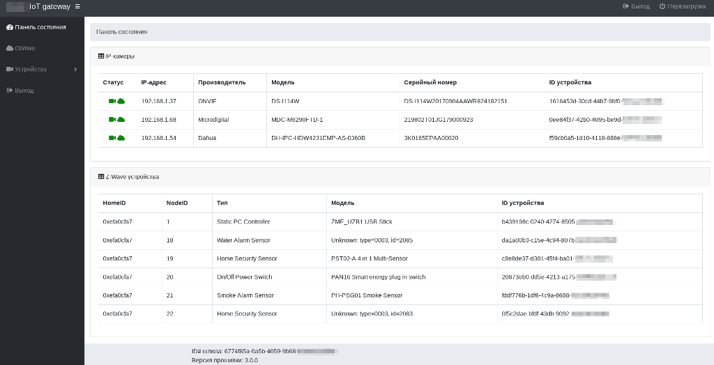
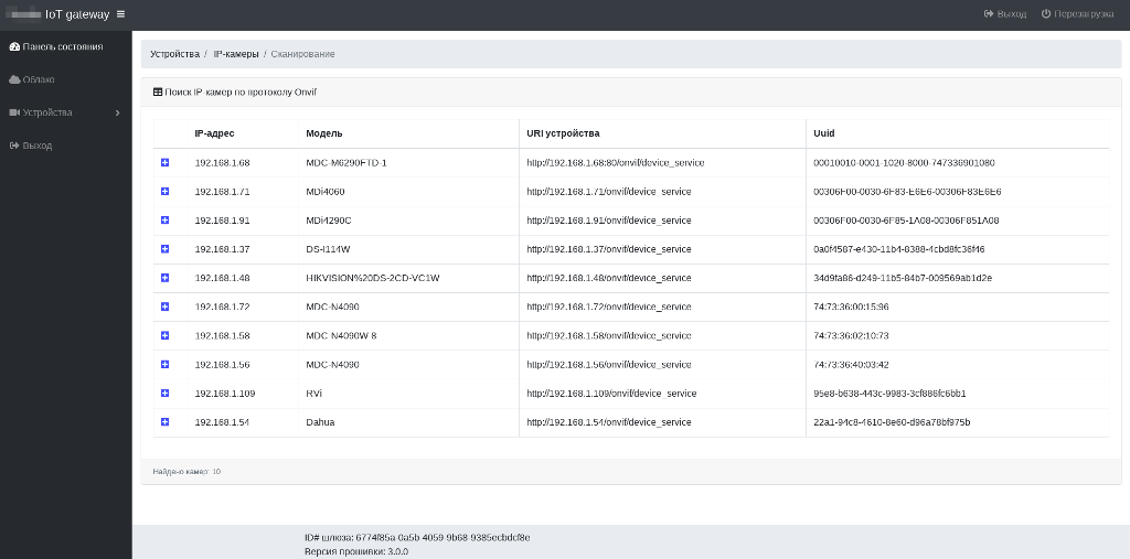
The smart interface of the smart home controller implements the search function for IP cameras in the PHP language, which is very convenient when interacting with web services via XML messages. When you select the menu items Devices> IP Cameras> Scan , the search algorithm for IP cameras starts, displaying the result in a table:
(click on the picture to open in higher resolution)
When adding a camera to the controller, you can specify the settings according to which it will interact with the cloud. Also at this stage, it is automatically assigned a unique identifier for the device, by which it can later be easily identified inside the cloud.
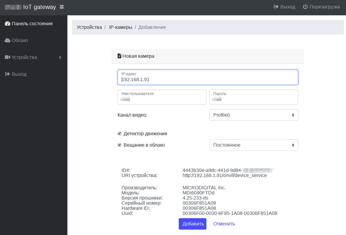
Next, a message is generated in the JSON format containing all the parameters of the added camera and sent to the server process of the smart home controller via the RESTful API command, where the camera parameters are decoded and stored in the internal SQLite database, and are also used to start the following processing threads:
- establishing an RTSP connection to receive video and audio streams;
- transcoding audio from the formats G.711 mu-Law, G.711 A-Law, G.723, etc. to AAC format;
- transcoding H.264 video and AAC audio streams to the FLV container and transmitting it to the cloud using RTMP;
- establishing a connection with the endpoint of the IP camera motion detector via ONVIF protocol and its periodic polling;
- periodically generating a thumbnail preview image and sending it to the cloud using the MQTT protocol;
- local recording of video and audio streams in the form of separate files in MP4 format on an SD- or Flash-card of a smart home controller.
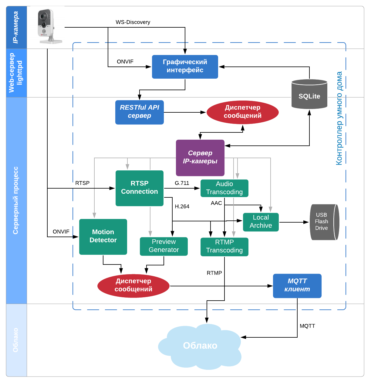
To establish a connection with cameras, transcoding, processing and recording video streams in the server process, functions from the FFmpeg 4.1.0 library are used.
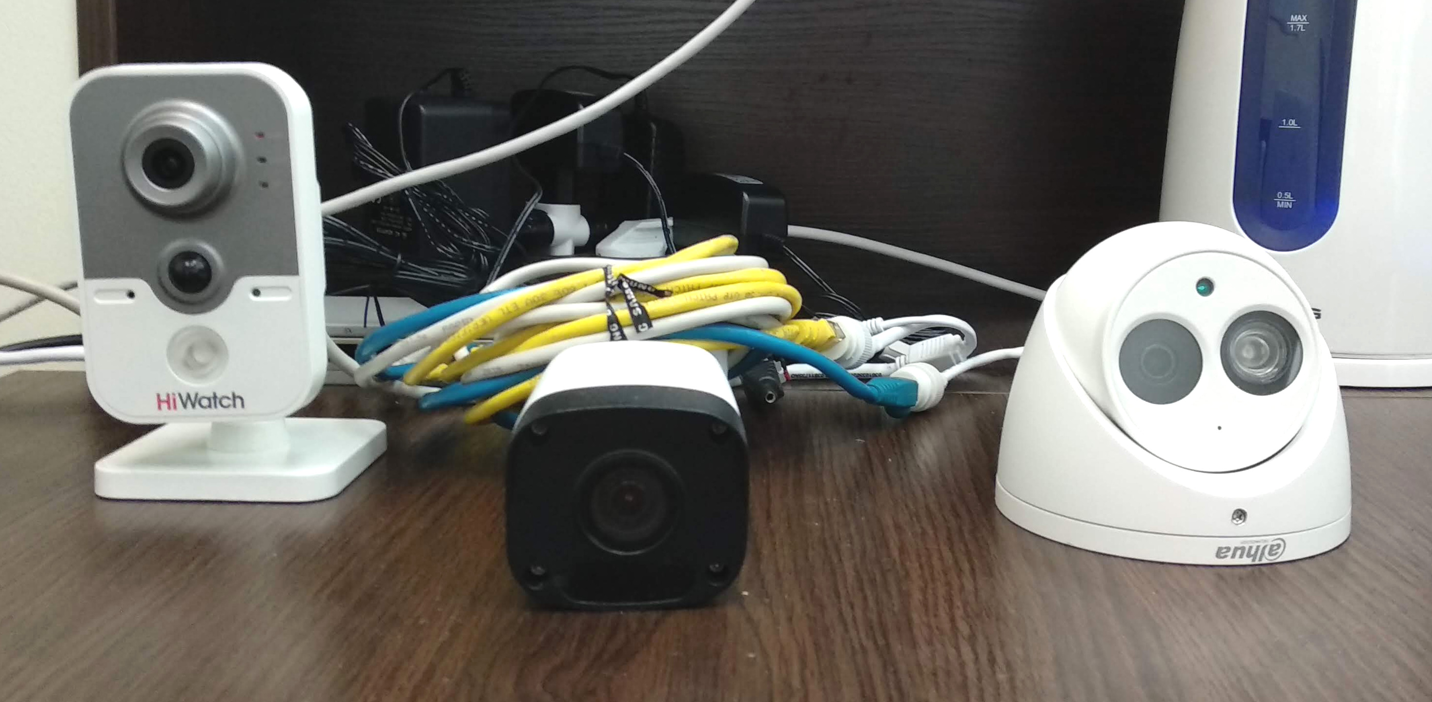
In the performance testing experiment, 3 cameras were connected to the controller:
- HiWatch DS-I114W (resolution - 720p, compression format - H.264, bit rate - 1 Mb / s, sound G.711 mu-Law);
- Microdigital MDC-M6290FTD-1 (resolution - 1080p, compression format - H.264, bit rate - 1 Mb / s, without sound);
- Dahua DH-IPC-HDW4231EMP-AS-0360B (resolution - 1080p, compression format - H.264, bitrate - 1.5 Mb / s, AAC sound).
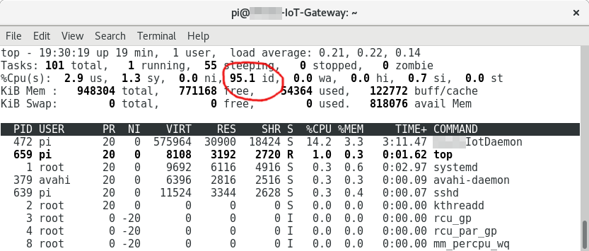
All three streams were simultaneously output to the cloud, sound transcoding was carried out from only one camera, recording of the local archive was disabled. CPU utilization was approximately 5%, RAM usage was 32 MB (per process), 56 MB (total together with the OS).
Thus, about 20-30 cameras (depending on resolution and bit rate) can be connected to the smart home controller, which is enough for a video surveillance system of a three-story cottage or a small warehouse. In tasks where high performance is required, you can use a nettop with an Intel multi-core processor and Linux Debian Sarge OS. Currently, the controller is undergoing trial operation, and data on its performance will be updated.
Cloud Interaction
Cloud smart home stores user data (video and sensor measurements) in the cloud. Cloud storage architecture will be discussed in more detail in the next article in our series. Now let's talk about the interface for transmitting information messages from the smart home controller to the cloud.
The states of connected devices and sensor measurements are transmitted using the MQTT protocol, which is often used in IoT projects because of its simplicity and energy efficiency. MQTT uses a client-server model when clients subscribe to certain topics within the broker and publish their messages. The broker sends messages to all subscribers according to the rules determined by the QoS (Quality of Service) level:
- QoS 0 - at most once (no delivery guarantee);
- QoS 1 - at least once (with delivery confirmation);
- QoS 2 - exactly once (with additional confirmation of delivery).
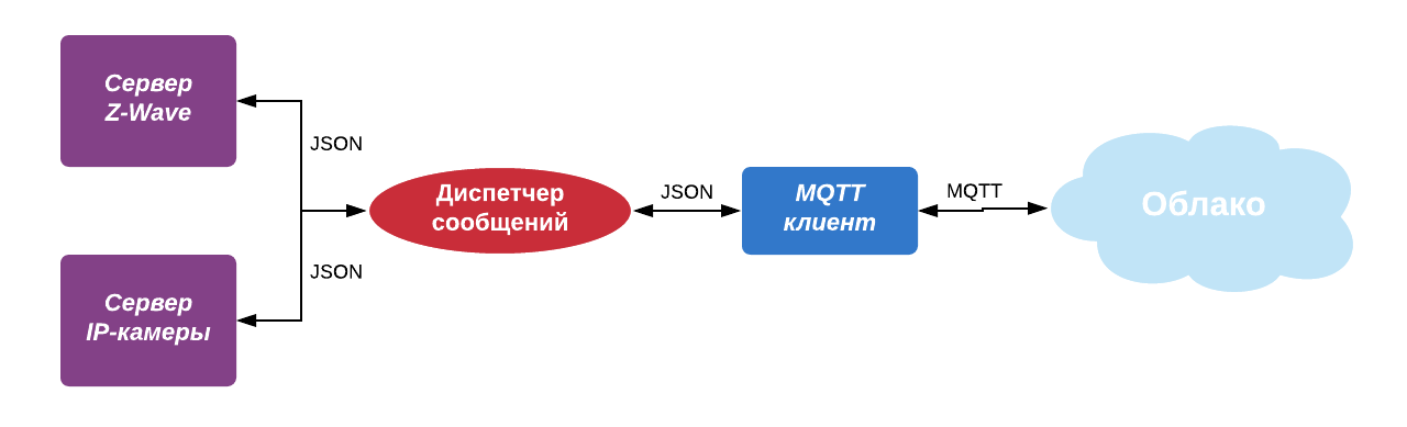
In our case, Eclipse Mosquitto is used as an MQTT broker. The topic name is the unique identifier of the smart home controller. The MQTT client inside the server process subscribes to this topic and translates JSON messages coming from the message manager into it. Conversely, messages from the MQTT broker are sent to them in the message manager, which then multiplexes them to its subscribers within the server process:
To transmit messages about the state of the smart home controller, the mechanism of saved messages retained messages of the MQTT protocol is used. This allows you to correctly monitor the moments of reconnections during power failures.
The MQTT client was developed based on the implementation of the Eclipse Paho library in C ++.
H.264 + AAC media streams are sent to the cloud via RTMP, where a cluster of media servers is responsible for their processing and storage. To optimally distribute the load in the cluster and select the least loaded media server, the smart home controller makes a preliminary request to the cloud load balancer and only then sends the media stream.
Conclusion
The article examined one specific implementation of a smart home controller based on the Raspberry Pi 3 B + microcomputer, which can receive, process information and manage equipment using the Z-Wave protocol, interact with IP cameras using the ONVIF protocol, and also exchange data and commands with the cloud MQTT and RTMP protocol service. A production logic engine has been developed based on a comparison of logical rules and facts presented in JSON format.
Now the smart home controller is being tested at several facilities in Moscow and the Moscow region.
In the next version of the controller, it is planned to connect devices of other types (RF, Bluetooth, WiFi, wired). For the convenience of users, the procedure for connecting sensors and IP cameras will be transferred to the mobile application. There are also ideas for optimizing the server process code and porting the software to the OpenWrt operating system. This will save on a separate controller and transfer the functionality of a smart home to a regular household router.
All Articles