Creating a connector symbol with “dynamic” text in OrCAD
When drawing a circuit diagram, we have to perform a bunch of routine actions. A few examples: drawing a library of electrical symbols, setting circuit names in a project, bringing the circuit to a form suitable for archiving, etc. For this reason, any help from CAD, in which the engineer works, is perceived very positively. Any person wants his work to be as easy as possible.
I was curious about the automation capabilities provided by the OrCAD circuit editor, which I often work in. The OrCAD Capture program contains a set of useful functions that help you to quickly perform repetitive actions and even introduce an “interactivity” element into the circuit. One of these functions is the ability to add various properties to objects in the circuit, in particular, to the pins (terminals) of electrical symbols. The properties can be varied, but one of the most interesting is the “NET NAME” property, with which you can dynamically display the name of the circuit connected to the component output.
When drawing connectors on a circuit, it is often necessary to designate circuits that match this connector inside the symbol of the connector. For example, this may be necessary if the scheme is performed according to the ESKD standard. But when creating the library symbol of the connector, most likely, it is still not known exactly which circuit will be connected to this or that contact. I would like to be able to "dynamically" register the circuit name inside the connector symbol, even when it is installed in the circuit. You can automate such a function in the OrCAD editor so that when you connect a specific circuit to the terminal of the connector, the name of that circuit will automatically appear inside the connector. To do this, we add a property called “NET NAME” to the output of our component, like this:
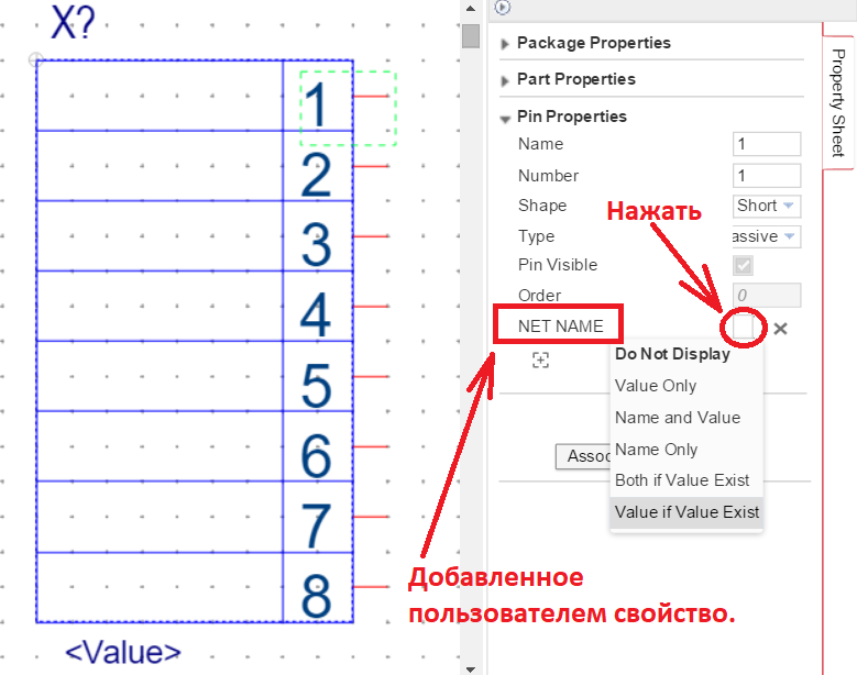
Then you need to select for this property the option of displaying the property value on the screen, “Value if Value Exist”, then when connected to a specific circuit in the circuit, the name of this circuit will automatically appear in a frame inside the connector. This method, in addition to convenience, also eliminates errors and confusion in the naming of the connector pins in the diagram.
As a result of such actions, the connected connector in the diagram will look like this:
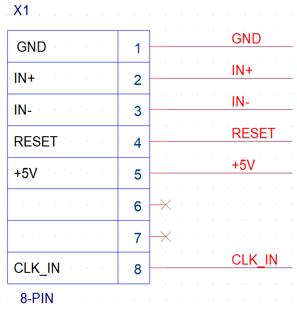
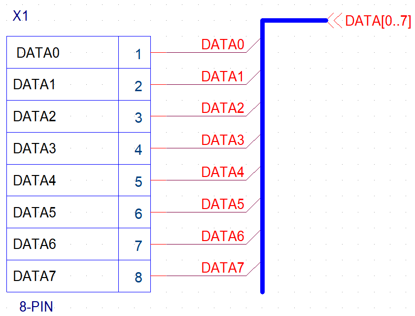
I must say that in these figures the names of the circuitry circuits that are connected to the connector are not very far from the symbol of the connector. In a real circuit, this may not be so, and simply lines of electrical circuits on which the circuit name is not visible will approach the connector. However, according to the inscriptions that appear inside the connector, the user can always find out and check whether the correct circuit is connected to a specific pin.
I was curious about the automation capabilities provided by the OrCAD circuit editor, which I often work in. The OrCAD Capture program contains a set of useful functions that help you to quickly perform repetitive actions and even introduce an “interactivity” element into the circuit. One of these functions is the ability to add various properties to objects in the circuit, in particular, to the pins (terminals) of electrical symbols. The properties can be varied, but one of the most interesting is the “NET NAME” property, with which you can dynamically display the name of the circuit connected to the component output.
When drawing connectors on a circuit, it is often necessary to designate circuits that match this connector inside the symbol of the connector. For example, this may be necessary if the scheme is performed according to the ESKD standard. But when creating the library symbol of the connector, most likely, it is still not known exactly which circuit will be connected to this or that contact. I would like to be able to "dynamically" register the circuit name inside the connector symbol, even when it is installed in the circuit. You can automate such a function in the OrCAD editor so that when you connect a specific circuit to the terminal of the connector, the name of that circuit will automatically appear inside the connector. To do this, we add a property called “NET NAME” to the output of our component, like this:
Then you need to select for this property the option of displaying the property value on the screen, “Value if Value Exist”, then when connected to a specific circuit in the circuit, the name of this circuit will automatically appear in a frame inside the connector. This method, in addition to convenience, also eliminates errors and confusion in the naming of the connector pins in the diagram.
As a result of such actions, the connected connector in the diagram will look like this:
I must say that in these figures the names of the circuitry circuits that are connected to the connector are not very far from the symbol of the connector. In a real circuit, this may not be so, and simply lines of electrical circuits on which the circuit name is not visible will approach the connector. However, according to the inscriptions that appear inside the connector, the user can always find out and check whether the correct circuit is connected to a specific pin.
All Articles