Training Cisco 200-125 CCNA v3.0. Day 29. PAT and NAT
Today we will study PAT (Port Address Translation), a technology for translating IP addresses using ports, and NAT (Network Address Translation), a technology for translating IP addresses of transit packets. PAT is a special case of NAT. We will cover three topics:
- private, or internal (intranet, local) IP addresses and public, or external IP addresses;
- NAT and PAT;
- configure NAT / PAT.
Let's start with the private IP addresses. We know that they are divided into three classes: A, B and C.

Class A internal addresses occupy the tens range from 10.0.0.0 to 10.255.255.255, and external addresses occupy the range from 1.0.0.0 to 9. 255.255.255 and from 11.0.0.0 to 126.255.255.255.
Class B internal addresses range from 172.16.0.0 to 172.31.255.255, and external addresses range from 128.0.0.0 to 172.15.255.255 and from 172.32.0.0 to 191.255.255.255.
Class C internal addresses range from 192.168.0.0 to 192.168.255.255, and external addresses range from 192.0.0 to 192.167.255.255 and from 192.169.0.0 to 223.255.255.255.
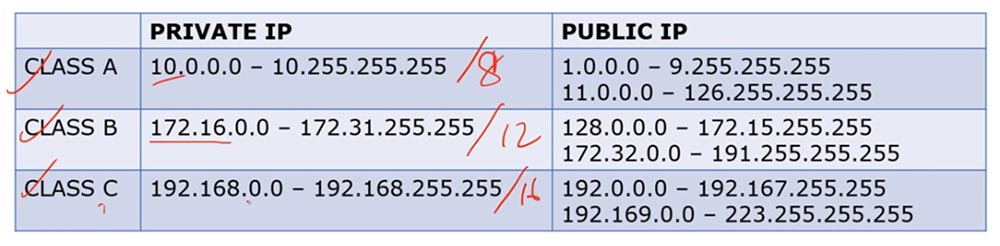
Class A addresses are addresses / 8, class B - / 12 and class C - / 16. Thus, the external and internal IP addresses of different classes occupy different ranges.
We have repeatedly discussed what the difference is between private and public IP addresses. In general terms, if we have a router and a group of internal IP addresses, when trying to get them to the Internet, the router converts them to external IP addresses. Internal addresses are used exclusively on local networks, and not on the Internet.
If I use the command line to view the network parameters of my computer, then I will see my internal LAN IP address 192.168.1.103 there.
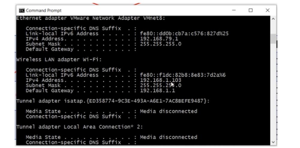
In order to find out your public IP address, you can use an Internet service such as "What is my IP"? As you can see, the external address of the computer 78.100.196.163 is different from its internal address.

In all cases, my computer is visible on the Internet precisely by the external IP address. So, the internal address of my computer is 192.168.1.103, and the external is 78.100.196.163. The internal address is used only for local communication, you can not access the Internet with it, for this you need a public IP address. You can remember why the separation was made into private and public addresses by reviewing the video tutorial Day 3.
Consider what NAT is. There are three types of NAT: static, dynamic, and overloaded NAT, or PAT.
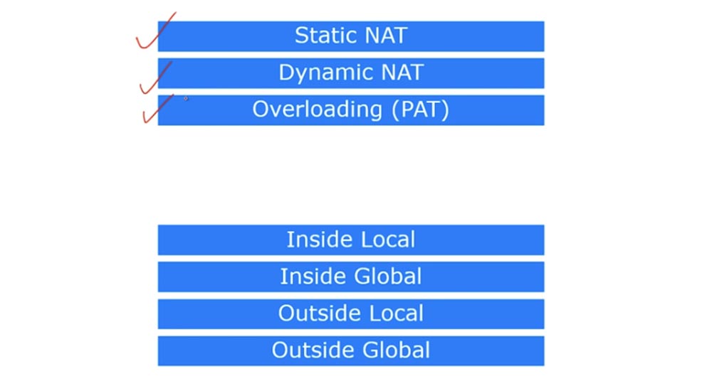
There are 4 terms in Cisco that describe NAT. As I said, NAT is a mechanism for converting internal addresses to external ones. If a device connected to the Internet receives a packet from another device from the local network, it will simply drop this packet, since the format of the internal address does not match the format of addresses used on the global Internet. Therefore, the device must receive a public IP address to access the Internet.
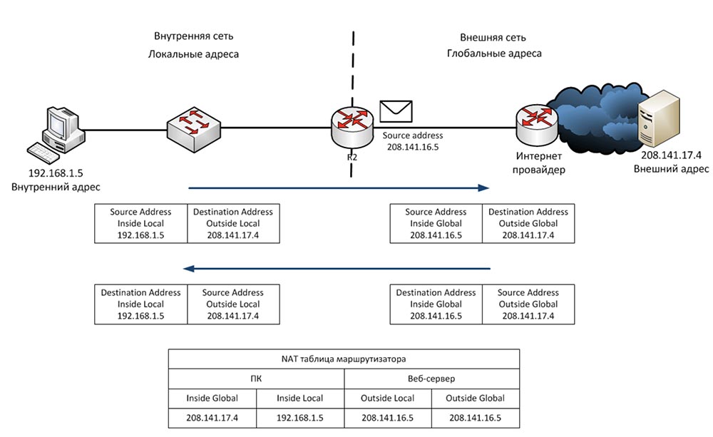
So, the first term is Inside Local, which means the IP address of the host on the internal LAN. Simply put, this is the primary source address of type 192.168.1.10. The second term, Inside Global, is the IP address of the local host, under which it is visible on the external network. In our case, this is the IP address of the external port of the router 200.124.22.10.
You can say that Inside Local is a private IP address, and Inside Global is a public IP address. Remember that the term Inside is used to refer to the source of traffic, and Outside is used to refer to the purpose of the traffic. Outside Local is the IP address of the host on the external network, under which it is visible to the internal network. Simply put, this is the recipient address visible from the internal network. An example of such an address is the IP address 200.124.22.100 of a device located on the Internet.

Outside Global is the host IP address visible on the external network. In most cases, the Outside Local and Outside Global addresses look the same, because even after the conversion, the destination IP address is the same for the source as before the conversion.
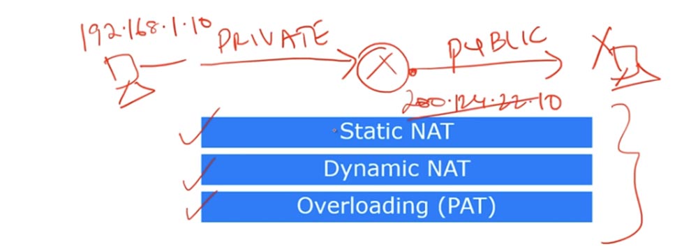
Consider what static NAT is. Static NAT means a one-to-one translation of internal IP addresses to external, or one-to-one conversion. When devices send traffic to the Internet, their Inside Local internal addresses translate to Inside Global internal addresses.
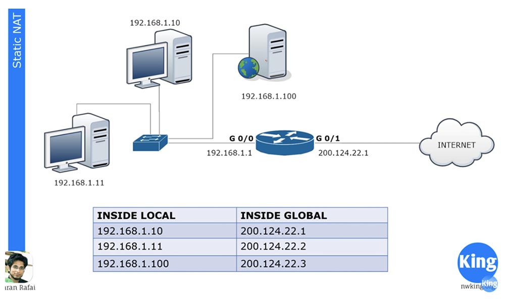
There are 3 devices in our local network, and when they are going to go online, each of them gets its own Inside Global address. These addresses are statically assigned to traffic sources. The one-to-one principle means that if 100 devices are located on the local network, they receive 100 external addresses.
NAT appeared to save the Internet, which ended with public IP addresses. Thanks to NAT, many companies, many networks can have one common external IP address, into which local device addresses will be converted when accessing the Internet. You can say that in this case of static NAT there is no saving in the number of addresses, since a hundred local computers are assigned a hundred external addresses, and you will be absolutely right. However, static NAT still has several advantages.
For example, we have a server with an internal IP address of 192.168.1.100. If some device from the Internet wants to contact him, he will not be able to do this using the internal destination address, for this he needs to use the external address of the server 200.124.22.3. If static NAT is configured in the router, all traffic addressed to 200.124.22.3 is automatically forwarded to 192.168.1.100. This provides external access to devices on the local network, in this case, to the company’s web server, which may be necessary in some cases.
Consider dynamic NAT. It is very similar to static, but does not assign permanent external addresses to each local device. For example, we have 3 local devices and only 2 external addresses. If the second device wants to go online, it will be assigned the first free IP address. If after it the web server wants to go online, the router will assign it the second available external address. If after that the first device wants to go to the external network, there will not be an available IP address for it, and the router will drop its packet.
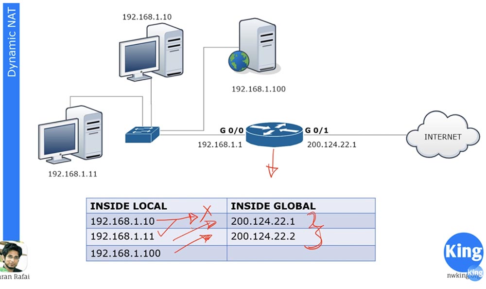
We can have hundreds of devices with internal IP addresses, and each of these devices can go online. But since we do not have a static assignment of external addresses, no more than 2 out of hundreds devices can access the Internet at the same time, because we have only two dynamically assigned external addresses.
Cisco devices have a fixed address translation time of 24 hours by default. It can be changed to 1,2,3, 10 minutes, at any time you like. After this time, external addresses are released and automatically returned to the address pool. If at this moment the first device wants to go online and any external address is available, then it will receive it. The router contains a NAT table, which is dynamically updated, and until the conversion time has expired, the assigned address is stored by the device. Simply put, dynamic NAT works on the principle: "who came first, they served."
Consider what constitutes an overloaded NAT, or PAT. This is the most common type of NAT. Your home network can have many devices - a PC, smartphone, laptop, tablet, and all of them are connected to a router that has one external IP address. So, PAT allows many devices with internal IP addresses to simultaneously go online under one external IP address. This is possible due to the fact that each private, internal IP address uses a specific port number during a communication session.
Suppose we have one public address 200.124.22.1 and many local devices. So, when accessing the Internet, all these hosts will receive the same address 200.124.22.1. The only thing that will distinguish them from each other is the port number.
If you remember the discussion of the transport layer, you know that the transport layer contains port numbers, and the source port number is a random number.

Suppose there is a host on the external network with an IP address of 200.124.22.10, which is connected to the Internet. If computer 192.168.1.11 wants to contact computer 200.124.22.10, it will create a random source port 51772. In this case, the destination port of the computer on the external network will be 80.
When the router receives a local computer packet sent to an external network, it translates its local Inside Local address to Inside Global address 200.124.22.1 and assigns 23556 to the port. The packet will reach the computer 200.124.22.10 and it will have to send a response back according to the handshake procedure, the destination will be address 200.124.22.1 and port 23556.
The router has a NAT translation table, therefore, having received a packet from an external computer, it will determine the Inside Local address corresponding to the Inside Global address as 192.168.1.11: 51772 and forward the packet to it. After that, the connection between the two computers can be considered established.
At the same time, you can have hundreds of devices that use the same address 200.124.22.1 for communication, but different port numbers, so they can all go online at the same time. This is why PAT is such a popular translation method.
Let's look at configuring static NAT. For any network, first of all, it is necessary to determine the input and output interfaces. The diagram shows a router through which traffic is transmitted from port G0 / 0 to port G0 / 1, that is, from an internal network to an external network. Thus, we have an input interface 192.168.1.1 and an output interface 200.124.22.1.
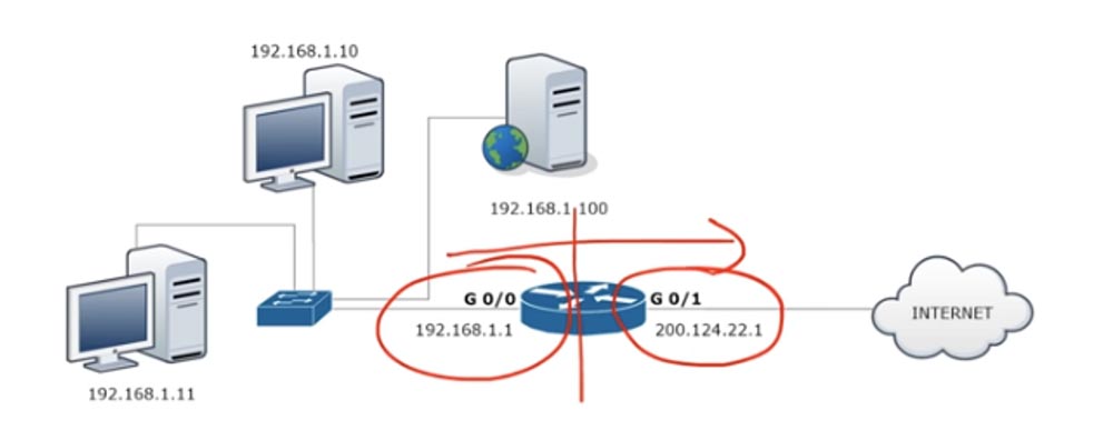
To configure NAT, we go to the G0 / 0 interface and set the ip addres 192.168.1.1 255.255.255.0 ip parameters and indicate that this interface is input using the ip nat inside command.
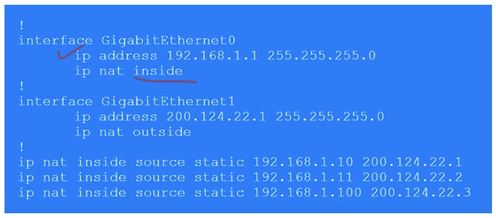
Similarly, we configure NAT on the output interface G0 / 1, specifying ip address 200.124.22.1, subnet mask 255.255.255.0 and ip nat outside. Remember that dynamic NAT translation is always done from the input to the output interface, from inside to outside. Naturally, for dynamic NAT, the answer comes to the input interface through the output interface, but when the traffic is initiated, it is the in-out direction that is triggered. In the case of static NAT, traffic initiation can occur in any of the directions - in-out or out-in.
Next, we need to create a table of static NAT, where each local address corresponds to a separate global address. In our case, there are 3 devices, so the table will consist of 3 entries that indicate the Inside Local IP address of the source, which translates into the Inside Global address: ip nat inside static 192.168.1.10 200.124.22.1.
Thus, in static NAT, you manually prescribe a translation for each local host address. Now I will go to Packet Tracer and make the settings described above.
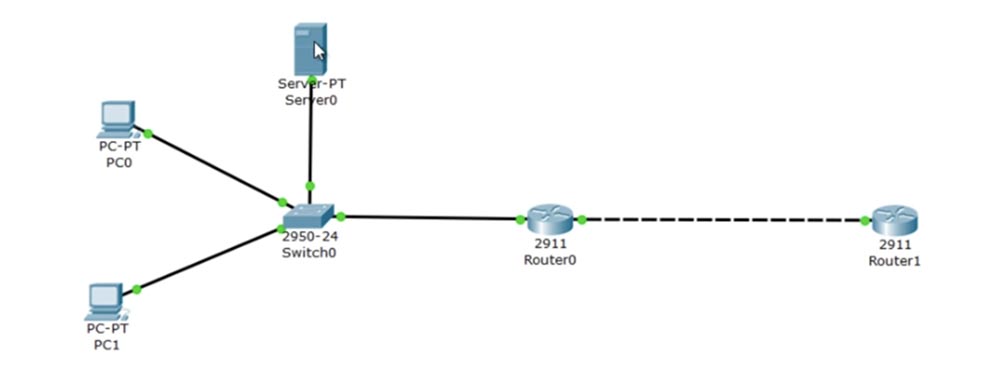
At the top we have the server 192.168.1.100, below is the computer 192.168.1.10 and at the very bottom is the computer 192.168.1.11. The G0 / 0 port of Router0 has an IP address of 192.168.1.1, and the G0 / 1 port has 200.124.22.1. In the "cloud" depicting the Internet, I placed Router1, which was assigned an IP address of 200.124.22.10.
I go into the settings of Router1 and type the debug ip icmp command. Now, as soon as the ping reaches this device, a debug message will appear in the settings window showing what kind of package it is.
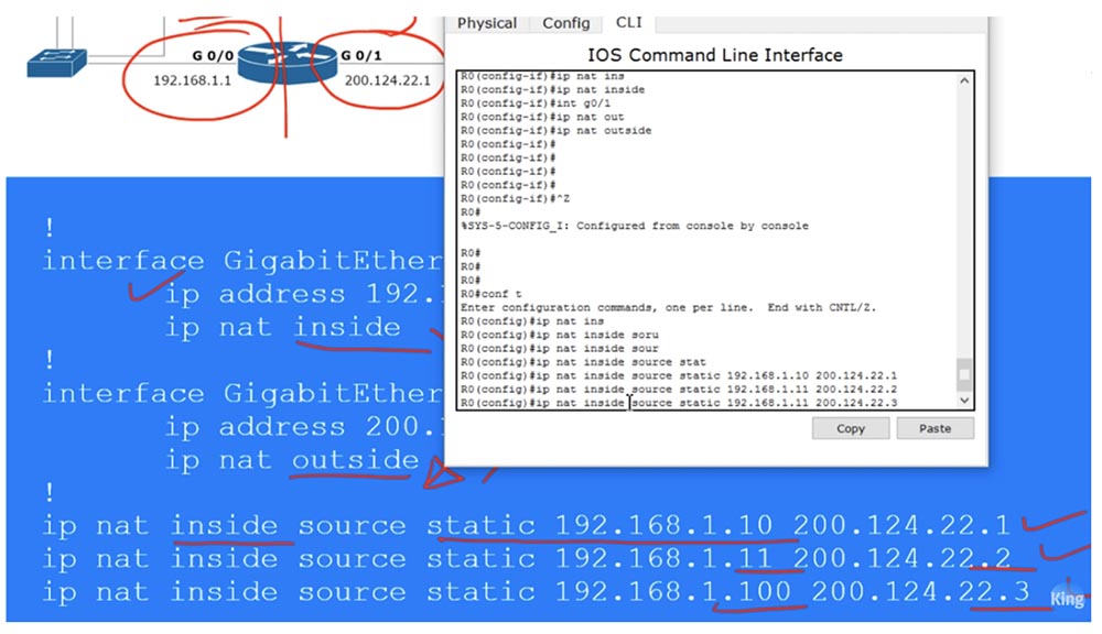
Let's set up the router Router0. I go into global settings mode and call the G0 / 0 interface. Next, I enter the ip nat inside command, then go to the g0 / 1 interface and enter the ip nat outside command. Thus, I assigned the input and output interfaces of the router. Now I need to manually configure the IP addresses, that is, transfer the lines of the table above to the settings:
Ip nat inside source static 192.168.1.10 200.124.22.1
Ip nat inside source static 192.168.1.11 200.124.22.2
Ip nat inside source static 192.168.1.100 200.124.22.3
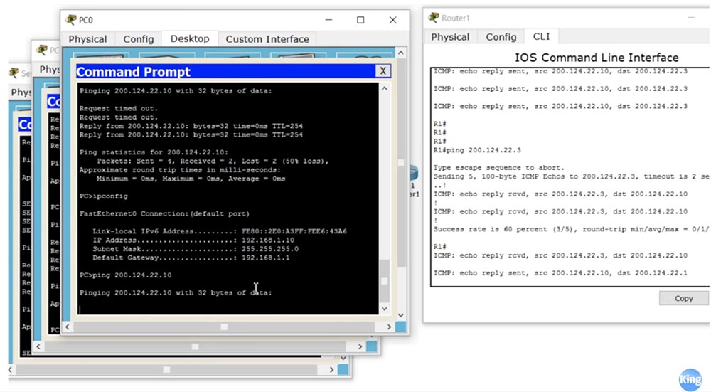
Now I will ping Router1 from each of our devices and see what IP addresses the ping received by it will show. To do this, I place the open CLI window of the R1 router on the right side of the screen to see debug messages. Now I go to the PC0 command line terminal and ping the address 200.124.22.10. After that, a message appears in the window that the ping was received from the IP address 200.124.22.1. This means that the IP address of the local computer 192.168.1.10 has been converted to the global address 200.124.22.1.

I do the same with the next local computer and see that its address has been converted to 200.124.22.2. Then I send ping from the server and see the address 200.124.22.3.
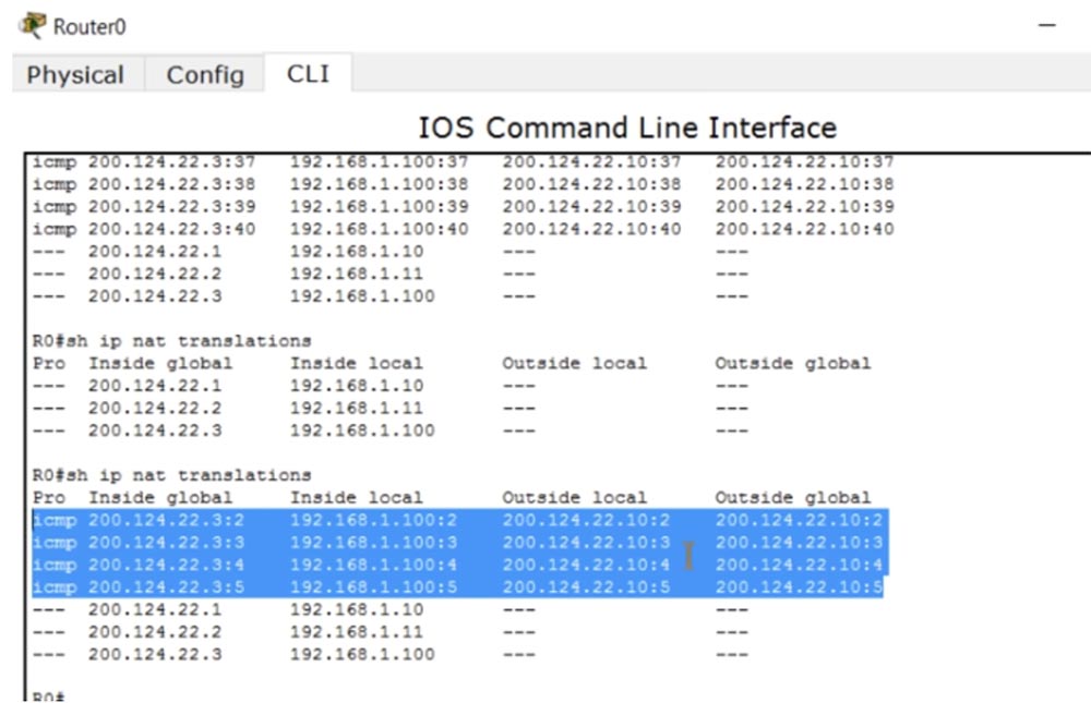
Thus, when the traffic from the LAN device reaches the router on which static NAT is configured, the router, in accordance with the table, converts the local IP address to the global one and sends the traffic to the external network. To check the NAT table, I enter the show ip nat translations command.
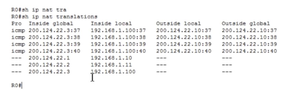
Now we can see all the transformations that the router makes. In the first column of Inside Global is the address of the device before the broadcast, that is, the address under which the device is visible from the external network, then the Inside Local address, that is, the device address on the local network. The third column shows Outside Local, and the fourth shows the Outside Global address, both of which are the same because we do not translate the destination IP address. As you can see, after a few seconds the table cleared up because a short ping timeout was set in Packet Tracer.
I can ping the server from the R1 router at the address 200.124.22.3, and if I go back to the settings of the router, you can see that the table was again filled with four ping lines with the converted destination address 192.168.1.100.
As I said, even if the broadcast timeout has worked, when the traffic is initiated from an external source, the NAT mechanism is automatically activated. This only happens when using static NAT.
Now let's see how dynamic NAT works. In our example, there are 2 public addresses for three devices on the local network, however, there can be tens and hundreds of such private hosts. At the same time, only 2 devices will be able to access the Internet at the same time. Consider what, besides this, is the difference between static and dynamic NAT.
As in the previous case, you first need to determine the input and output interfaces of the router. Next, we create a kind of access list, but this is not the ACL that we talked about in the previous lesson. This access list is used to identify the traffic we want to convert. Here the new term “interesting traffic”, or “interesting traffic”, appears. This is traffic that interests you for some reason, and when this traffic matches the conditions of the access list, it falls under the action of NAT and is converted. This term is applicable to traffic in many cases, for example, in the case of VPNs, “interesting” is called traffic that they are going to pass through a VPN tunnel.
We must create an ACL that identifies interesting traffic, in our case it is the traffic of the whole network 192.168.1.0, with which the reverse mask 0.0.0.255 is indicated.

Then we need to create a NAT pool, for which we use the ip nat pool <pool name> command and specify the pool of IP addresses 200.124.22.1 200.124.22.2. This means that we provide only two external IP addresses. The command then uses the netmask keyword and enters the subnet mask 255.255.255.252. The last octet of the mask is (255 - the number of pool addresses is 1), so if you have 254 addresses in the pool, then the subnet mask will be 255.255.255.0. This is a very important parameter, so when setting up dynamic NAT, be sure to enter the correct netmask value.
Next, we use a command that starts the NAT mechanism: ip nat inside sourse list 1 pool NWKING, where NWKING is the pool name and list 1 means ACL access list number1. Remember - in order for this command to work, you must first create a pool of dynamic addresses and an access list.
So, under our conditions, the first device that wants to access the Internet can do this, the second device too, but the third will have to wait until one of the pool addresses is free. Configuring dynamic NAT consists of 4 steps: determining the input and output interface, determining the "interesting" traffic, creating a NAT pool and setting it up.
Now we will go to Packet Tracer and try to configure dynamic NAT. First, we must remove the static NAT settings, for which we enter the commands in sequence:
no Ip nat inside source static 192.168.1.10 200.124.22.1
no Ip nat inside source static 192.168.1.11 200.124.22.2
no Ip nat inside source static 192.168.1.100 200.124.22.3.
Next, I create the List 1 access list for the entire network with the access-list 1 permit 192.168.1.0 0.0.0.255 command and configure the NAT pool using the ip nat pool NWKING 200.124.22.1 200.124.22.2 netmask 255.255.255.252 command. In this command, I specified the name of the pool, the addresses that enter it, and the network mask.
Then I indicate whether this NAT is internal or external, and the source where NAT should get information from, in our case it is list, using the ip nat inside source list 1 command. After that, the system will give a hint - do you need a whole pool or a specific interface . I choose pool because we have more than 1 external address. If you select interface, you will need to specify a port with a specific IP address. In the final form, the command will look like this: ip nat inside source list 1 pool NWKING. Now this pool consists of two addresses 200.124.22.1 200.124.22.2, however you can freely change them or add new addresses that are not tied to a specific interface.
You must ensure that your routing table is updated so that any of these IP addresses in the pool must be directed to this device, otherwise you will not receive return traffic. To make sure the settings are working, we will repeat the pinging procedure of the cloud router, which was performed for static NAT. I will open the Router 1 router window to see debug mode messages, and ping it from each of the 3 devices.
We see that all source addresses where ping packets come from correspond to the settings.At the same time, ping from the PC0 computer does not pass, because it did not have enough free external address. If you go into the settings of Router 1, you can see that the pool addresses 200.124.22.1 and 200.124.22.2 are currently used. Now I turn off the broadcast, and you will see how the lines disappear one after another. I start ping again from PC0, and as you can see, now everything works, because he was able to get the freed up external address 200.124.22.1.
How can I clear the NAT table and cancel the given address translation? We go into the settings of the router Router0 and type the command clear ip nat translation * with an asterisk at the end of the line. If you now look at the conversion status using the show ip nat translation command, the system will give us an empty string.
NAT show ip nat statistics.

, , NAT/PAT. , 0, . , hits misses ( ), .
IP- – NAT, PAT. PAT , NAT: , «» , NAT PAT. , , , PAT . NAT PAT overload, . NAT PAT.

, NWKING, , 200.124.22.1, 255.255.255.0. , ip nat 1 pool NWKING 200.124.22.1 200.124.22.1 netmask 255.255.255.0 source interface 200.124.22.1 G0/1. IP-.
IP-, . , . NAT , , , NAT IP- . , IP- .
Packet Tracer. NAT no Ip nat inside source list 1 NWKING NAT no Ip nat pool NWKING 200.124.22.1 200.124.22.2 netmask 225.255.255.252.
PAT Ip nat pool NWKING 200.124.22.2 200.124.22.2 netmask 225.255.255.255. IP-, , 200.124.22.1, 200.124.22.2. , .
PAT Ip nat inside source list 1 pool NWKING overload. PAT. , , , PC0 Router1 200.124.22.10. , , , , IP- 200.124.22.2. , PC1 Server0.
, Router0. , , , Router1 IP- 200.124.22.2.
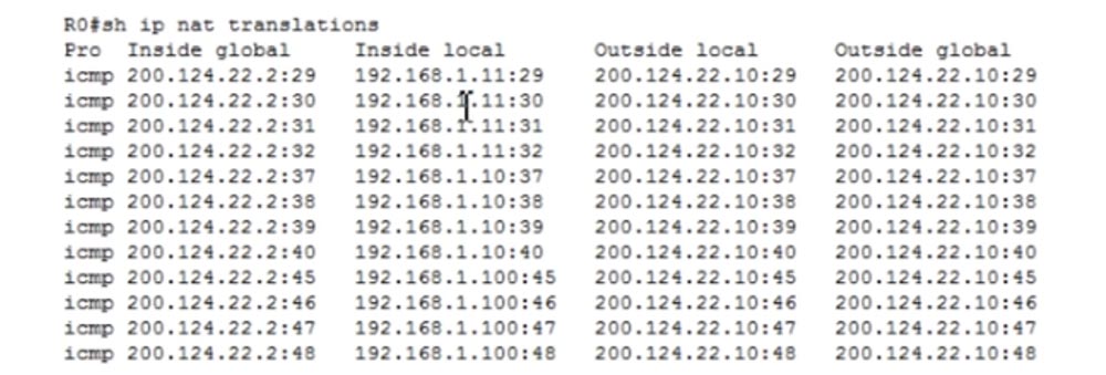
show ip nat statistics, PAT.

, , , 12, .
- — Ip nat inside source list 1 interface gigabit Ethernet g0/1 overload. PC0, , 200.124.22.1, ! : , , NAT- IP- . .
, . Packet Tracer, NAT PAT. ICND1 — CCNA, , , .
Thank you for staying with us. Do you like our articles? Want to see more interesting materials? Support us by placing an order or recommending it to your friends, a 30% discount for Habr users on a unique analogue of entry-level servers that was invented by us for you: The whole truth about VPS (KVM) E5-2650 v4 (6 Cores) 10GB DDR4 240GB SSD 1Gbps from $ 20 or how to divide the server? (options are available with RAID1 and RAID10, up to 24 cores and up to 40GB DDR4).
Dell R730xd 2 times cheaper? Only we have 2 x Intel TetraDeca-Core Xeon 2x E5-2697v3 2.6GHz 14C 64GB DDR4 4x960GB SSD 1Gbps 100 TV from $ 199 in the Netherlands! Dell R420 - 2x E5-2430 2.2Ghz 6C 128GB DDR3 2x960GB SSD 1Gbps 100TB - from $ 99! Read about How to Build Infrastructure Bldg. class c using Dell R730xd E5-2650 v4 servers costing 9,000 euros for a penny?
- private, or internal (intranet, local) IP addresses and public, or external IP addresses;
- NAT and PAT;
- configure NAT / PAT.
Let's start with the private IP addresses. We know that they are divided into three classes: A, B and C.
Class A internal addresses occupy the tens range from 10.0.0.0 to 10.255.255.255, and external addresses occupy the range from 1.0.0.0 to 9. 255.255.255 and from 11.0.0.0 to 126.255.255.255.
Class B internal addresses range from 172.16.0.0 to 172.31.255.255, and external addresses range from 128.0.0.0 to 172.15.255.255 and from 172.32.0.0 to 191.255.255.255.
Class C internal addresses range from 192.168.0.0 to 192.168.255.255, and external addresses range from 192.0.0 to 192.167.255.255 and from 192.169.0.0 to 223.255.255.255.
Class A addresses are addresses / 8, class B - / 12 and class C - / 16. Thus, the external and internal IP addresses of different classes occupy different ranges.
We have repeatedly discussed what the difference is between private and public IP addresses. In general terms, if we have a router and a group of internal IP addresses, when trying to get them to the Internet, the router converts them to external IP addresses. Internal addresses are used exclusively on local networks, and not on the Internet.
If I use the command line to view the network parameters of my computer, then I will see my internal LAN IP address 192.168.1.103 there.
In order to find out your public IP address, you can use an Internet service such as "What is my IP"? As you can see, the external address of the computer 78.100.196.163 is different from its internal address.
In all cases, my computer is visible on the Internet precisely by the external IP address. So, the internal address of my computer is 192.168.1.103, and the external is 78.100.196.163. The internal address is used only for local communication, you can not access the Internet with it, for this you need a public IP address. You can remember why the separation was made into private and public addresses by reviewing the video tutorial Day 3.
Consider what NAT is. There are three types of NAT: static, dynamic, and overloaded NAT, or PAT.
There are 4 terms in Cisco that describe NAT. As I said, NAT is a mechanism for converting internal addresses to external ones. If a device connected to the Internet receives a packet from another device from the local network, it will simply drop this packet, since the format of the internal address does not match the format of addresses used on the global Internet. Therefore, the device must receive a public IP address to access the Internet.
So, the first term is Inside Local, which means the IP address of the host on the internal LAN. Simply put, this is the primary source address of type 192.168.1.10. The second term, Inside Global, is the IP address of the local host, under which it is visible on the external network. In our case, this is the IP address of the external port of the router 200.124.22.10.
You can say that Inside Local is a private IP address, and Inside Global is a public IP address. Remember that the term Inside is used to refer to the source of traffic, and Outside is used to refer to the purpose of the traffic. Outside Local is the IP address of the host on the external network, under which it is visible to the internal network. Simply put, this is the recipient address visible from the internal network. An example of such an address is the IP address 200.124.22.100 of a device located on the Internet.
Outside Global is the host IP address visible on the external network. In most cases, the Outside Local and Outside Global addresses look the same, because even after the conversion, the destination IP address is the same for the source as before the conversion.
Consider what static NAT is. Static NAT means a one-to-one translation of internal IP addresses to external, or one-to-one conversion. When devices send traffic to the Internet, their Inside Local internal addresses translate to Inside Global internal addresses.
There are 3 devices in our local network, and when they are going to go online, each of them gets its own Inside Global address. These addresses are statically assigned to traffic sources. The one-to-one principle means that if 100 devices are located on the local network, they receive 100 external addresses.
NAT appeared to save the Internet, which ended with public IP addresses. Thanks to NAT, many companies, many networks can have one common external IP address, into which local device addresses will be converted when accessing the Internet. You can say that in this case of static NAT there is no saving in the number of addresses, since a hundred local computers are assigned a hundred external addresses, and you will be absolutely right. However, static NAT still has several advantages.
For example, we have a server with an internal IP address of 192.168.1.100. If some device from the Internet wants to contact him, he will not be able to do this using the internal destination address, for this he needs to use the external address of the server 200.124.22.3. If static NAT is configured in the router, all traffic addressed to 200.124.22.3 is automatically forwarded to 192.168.1.100. This provides external access to devices on the local network, in this case, to the company’s web server, which may be necessary in some cases.
Consider dynamic NAT. It is very similar to static, but does not assign permanent external addresses to each local device. For example, we have 3 local devices and only 2 external addresses. If the second device wants to go online, it will be assigned the first free IP address. If after it the web server wants to go online, the router will assign it the second available external address. If after that the first device wants to go to the external network, there will not be an available IP address for it, and the router will drop its packet.
We can have hundreds of devices with internal IP addresses, and each of these devices can go online. But since we do not have a static assignment of external addresses, no more than 2 out of hundreds devices can access the Internet at the same time, because we have only two dynamically assigned external addresses.
Cisco devices have a fixed address translation time of 24 hours by default. It can be changed to 1,2,3, 10 minutes, at any time you like. After this time, external addresses are released and automatically returned to the address pool. If at this moment the first device wants to go online and any external address is available, then it will receive it. The router contains a NAT table, which is dynamically updated, and until the conversion time has expired, the assigned address is stored by the device. Simply put, dynamic NAT works on the principle: "who came first, they served."
Consider what constitutes an overloaded NAT, or PAT. This is the most common type of NAT. Your home network can have many devices - a PC, smartphone, laptop, tablet, and all of them are connected to a router that has one external IP address. So, PAT allows many devices with internal IP addresses to simultaneously go online under one external IP address. This is possible due to the fact that each private, internal IP address uses a specific port number during a communication session.
Suppose we have one public address 200.124.22.1 and many local devices. So, when accessing the Internet, all these hosts will receive the same address 200.124.22.1. The only thing that will distinguish them from each other is the port number.
If you remember the discussion of the transport layer, you know that the transport layer contains port numbers, and the source port number is a random number.
Suppose there is a host on the external network with an IP address of 200.124.22.10, which is connected to the Internet. If computer 192.168.1.11 wants to contact computer 200.124.22.10, it will create a random source port 51772. In this case, the destination port of the computer on the external network will be 80.
When the router receives a local computer packet sent to an external network, it translates its local Inside Local address to Inside Global address 200.124.22.1 and assigns 23556 to the port. The packet will reach the computer 200.124.22.10 and it will have to send a response back according to the handshake procedure, the destination will be address 200.124.22.1 and port 23556.
The router has a NAT translation table, therefore, having received a packet from an external computer, it will determine the Inside Local address corresponding to the Inside Global address as 192.168.1.11: 51772 and forward the packet to it. After that, the connection between the two computers can be considered established.
At the same time, you can have hundreds of devices that use the same address 200.124.22.1 for communication, but different port numbers, so they can all go online at the same time. This is why PAT is such a popular translation method.
Let's look at configuring static NAT. For any network, first of all, it is necessary to determine the input and output interfaces. The diagram shows a router through which traffic is transmitted from port G0 / 0 to port G0 / 1, that is, from an internal network to an external network. Thus, we have an input interface 192.168.1.1 and an output interface 200.124.22.1.
To configure NAT, we go to the G0 / 0 interface and set the ip addres 192.168.1.1 255.255.255.0 ip parameters and indicate that this interface is input using the ip nat inside command.
Similarly, we configure NAT on the output interface G0 / 1, specifying ip address 200.124.22.1, subnet mask 255.255.255.0 and ip nat outside. Remember that dynamic NAT translation is always done from the input to the output interface, from inside to outside. Naturally, for dynamic NAT, the answer comes to the input interface through the output interface, but when the traffic is initiated, it is the in-out direction that is triggered. In the case of static NAT, traffic initiation can occur in any of the directions - in-out or out-in.
Next, we need to create a table of static NAT, where each local address corresponds to a separate global address. In our case, there are 3 devices, so the table will consist of 3 entries that indicate the Inside Local IP address of the source, which translates into the Inside Global address: ip nat inside static 192.168.1.10 200.124.22.1.
Thus, in static NAT, you manually prescribe a translation for each local host address. Now I will go to Packet Tracer and make the settings described above.
At the top we have the server 192.168.1.100, below is the computer 192.168.1.10 and at the very bottom is the computer 192.168.1.11. The G0 / 0 port of Router0 has an IP address of 192.168.1.1, and the G0 / 1 port has 200.124.22.1. In the "cloud" depicting the Internet, I placed Router1, which was assigned an IP address of 200.124.22.10.
I go into the settings of Router1 and type the debug ip icmp command. Now, as soon as the ping reaches this device, a debug message will appear in the settings window showing what kind of package it is.
Let's set up the router Router0. I go into global settings mode and call the G0 / 0 interface. Next, I enter the ip nat inside command, then go to the g0 / 1 interface and enter the ip nat outside command. Thus, I assigned the input and output interfaces of the router. Now I need to manually configure the IP addresses, that is, transfer the lines of the table above to the settings:
Ip nat inside source static 192.168.1.10 200.124.22.1
Ip nat inside source static 192.168.1.11 200.124.22.2
Ip nat inside source static 192.168.1.100 200.124.22.3
Now I will ping Router1 from each of our devices and see what IP addresses the ping received by it will show. To do this, I place the open CLI window of the R1 router on the right side of the screen to see debug messages. Now I go to the PC0 command line terminal and ping the address 200.124.22.10. After that, a message appears in the window that the ping was received from the IP address 200.124.22.1. This means that the IP address of the local computer 192.168.1.10 has been converted to the global address 200.124.22.1.
I do the same with the next local computer and see that its address has been converted to 200.124.22.2. Then I send ping from the server and see the address 200.124.22.3.
Thus, when the traffic from the LAN device reaches the router on which static NAT is configured, the router, in accordance with the table, converts the local IP address to the global one and sends the traffic to the external network. To check the NAT table, I enter the show ip nat translations command.
Now we can see all the transformations that the router makes. In the first column of Inside Global is the address of the device before the broadcast, that is, the address under which the device is visible from the external network, then the Inside Local address, that is, the device address on the local network. The third column shows Outside Local, and the fourth shows the Outside Global address, both of which are the same because we do not translate the destination IP address. As you can see, after a few seconds the table cleared up because a short ping timeout was set in Packet Tracer.
I can ping the server from the R1 router at the address 200.124.22.3, and if I go back to the settings of the router, you can see that the table was again filled with four ping lines with the converted destination address 192.168.1.100.
As I said, even if the broadcast timeout has worked, when the traffic is initiated from an external source, the NAT mechanism is automatically activated. This only happens when using static NAT.
Now let's see how dynamic NAT works. In our example, there are 2 public addresses for three devices on the local network, however, there can be tens and hundreds of such private hosts. At the same time, only 2 devices will be able to access the Internet at the same time. Consider what, besides this, is the difference between static and dynamic NAT.
As in the previous case, you first need to determine the input and output interfaces of the router. Next, we create a kind of access list, but this is not the ACL that we talked about in the previous lesson. This access list is used to identify the traffic we want to convert. Here the new term “interesting traffic”, or “interesting traffic”, appears. This is traffic that interests you for some reason, and when this traffic matches the conditions of the access list, it falls under the action of NAT and is converted. This term is applicable to traffic in many cases, for example, in the case of VPNs, “interesting” is called traffic that they are going to pass through a VPN tunnel.
We must create an ACL that identifies interesting traffic, in our case it is the traffic of the whole network 192.168.1.0, with which the reverse mask 0.0.0.255 is indicated.
Then we need to create a NAT pool, for which we use the ip nat pool <pool name> command and specify the pool of IP addresses 200.124.22.1 200.124.22.2. This means that we provide only two external IP addresses. The command then uses the netmask keyword and enters the subnet mask 255.255.255.252. The last octet of the mask is (255 - the number of pool addresses is 1), so if you have 254 addresses in the pool, then the subnet mask will be 255.255.255.0. This is a very important parameter, so when setting up dynamic NAT, be sure to enter the correct netmask value.
Next, we use a command that starts the NAT mechanism: ip nat inside sourse list 1 pool NWKING, where NWKING is the pool name and list 1 means ACL access list number1. Remember - in order for this command to work, you must first create a pool of dynamic addresses and an access list.
So, under our conditions, the first device that wants to access the Internet can do this, the second device too, but the third will have to wait until one of the pool addresses is free. Configuring dynamic NAT consists of 4 steps: determining the input and output interface, determining the "interesting" traffic, creating a NAT pool and setting it up.
Now we will go to Packet Tracer and try to configure dynamic NAT. First, we must remove the static NAT settings, for which we enter the commands in sequence:
no Ip nat inside source static 192.168.1.10 200.124.22.1
no Ip nat inside source static 192.168.1.11 200.124.22.2
no Ip nat inside source static 192.168.1.100 200.124.22.3.
Next, I create the List 1 access list for the entire network with the access-list 1 permit 192.168.1.0 0.0.0.255 command and configure the NAT pool using the ip nat pool NWKING 200.124.22.1 200.124.22.2 netmask 255.255.255.252 command. In this command, I specified the name of the pool, the addresses that enter it, and the network mask.
Then I indicate whether this NAT is internal or external, and the source where NAT should get information from, in our case it is list, using the ip nat inside source list 1 command. After that, the system will give a hint - do you need a whole pool or a specific interface . I choose pool because we have more than 1 external address. If you select interface, you will need to specify a port with a specific IP address. In the final form, the command will look like this: ip nat inside source list 1 pool NWKING. Now this pool consists of two addresses 200.124.22.1 200.124.22.2, however you can freely change them or add new addresses that are not tied to a specific interface.
You must ensure that your routing table is updated so that any of these IP addresses in the pool must be directed to this device, otherwise you will not receive return traffic. To make sure the settings are working, we will repeat the pinging procedure of the cloud router, which was performed for static NAT. I will open the Router 1 router window to see debug mode messages, and ping it from each of the 3 devices.
We see that all source addresses where ping packets come from correspond to the settings.At the same time, ping from the PC0 computer does not pass, because it did not have enough free external address. If you go into the settings of Router 1, you can see that the pool addresses 200.124.22.1 and 200.124.22.2 are currently used. Now I turn off the broadcast, and you will see how the lines disappear one after another. I start ping again from PC0, and as you can see, now everything works, because he was able to get the freed up external address 200.124.22.1.
How can I clear the NAT table and cancel the given address translation? We go into the settings of the router Router0 and type the command clear ip nat translation * with an asterisk at the end of the line. If you now look at the conversion status using the show ip nat translation command, the system will give us an empty string.
NAT show ip nat statistics.
, , NAT/PAT. , 0, . , hits misses ( ), .
IP- – NAT, PAT. PAT , NAT: , «» , NAT PAT. , , , PAT . NAT PAT overload, . NAT PAT.
, NWKING, , 200.124.22.1, 255.255.255.0. , ip nat 1 pool NWKING 200.124.22.1 200.124.22.1 netmask 255.255.255.0 source interface 200.124.22.1 G0/1. IP-.
IP-, . , . NAT , , , NAT IP- . , IP- .
Packet Tracer. NAT no Ip nat inside source list 1 NWKING NAT no Ip nat pool NWKING 200.124.22.1 200.124.22.2 netmask 225.255.255.252.
PAT Ip nat pool NWKING 200.124.22.2 200.124.22.2 netmask 225.255.255.255. IP-, , 200.124.22.1, 200.124.22.2. , .
PAT Ip nat inside source list 1 pool NWKING overload. PAT. , , , PC0 Router1 200.124.22.10. , , , , IP- 200.124.22.2. , PC1 Server0.
, Router0. , , , Router1 IP- 200.124.22.2.
show ip nat statistics, PAT.
, , , 12, .
- — Ip nat inside source list 1 interface gigabit Ethernet g0/1 overload. PC0, , 200.124.22.1, ! : , , NAT- IP- . .
, . Packet Tracer, NAT PAT. ICND1 — CCNA, , , .
Thank you for staying with us. Do you like our articles? Want to see more interesting materials? Support us by placing an order or recommending it to your friends, a 30% discount for Habr users on a unique analogue of entry-level servers that was invented by us for you: The whole truth about VPS (KVM) E5-2650 v4 (6 Cores) 10GB DDR4 240GB SSD 1Gbps from $ 20 or how to divide the server? (options are available with RAID1 and RAID10, up to 24 cores and up to 40GB DDR4).
Dell R730xd 2 times cheaper? Only we have 2 x Intel TetraDeca-Core Xeon 2x E5-2697v3 2.6GHz 14C 64GB DDR4 4x960GB SSD 1Gbps 100 TV from $ 199 in the Netherlands! Dell R420 - 2x E5-2430 2.2Ghz 6C 128GB DDR3 2x960GB SSD 1Gbps 100TB - from $ 99! Read about How to Build Infrastructure Bldg. class c using Dell R730xd E5-2650 v4 servers costing 9,000 euros for a penny?
All Articles