Learning STM8S Slow Start. Part 0
MK family STM8S relative to STM8L / 32 has a smaller arsenal of peripherals, but allows you to easily understand the basics and gain the necessary skills to work with his older brothers.
When writing this article, I assume that the reader can:
I consider the objectives of the article:
I have several STM8S105K6 in the LQFP32 package, it is from this family, so I choose it.
You can choose any MK within the series.
There are ready Discovery boards from ST, you can buy from the Chinese or order from other resources. There are ready-made boards for the STM8S103F3P6 and the like from the Chinese.
But, it should be noted that ready-made boards are designed for training.
On the manufacturer’s website st.com , we find our MK and download documents to it:
Reference manual: RM0016 - a common document for all MK families STM8S and STM8AF. Next is RM.
Datasheet: I have a DS5855 document for the STM8S105C4 / 6, STM8S105K4 / 6 and STM8S105S4 / 6. Further DS.
From the delicious things he has (superficially):
I see two options for working with MK:
I do not consider working with contact breadboards because I do not use it.
Plus I need a programmer, I have a Chinese ST-Link V2. Able to program and STM8 and STM32.
For me, the question of choice is not yet relevant, I work in the IAR for STM8, because it made a project on which I am currently working, for the same reason the old version.
We go to the site iar.com , in the search we type the model of our MK.
Download the IAR Embedded Workbench for STM8, select the size-limited evaluation when installing, and put up with a limit of 8 KB of code. Or buy. There are hacked versions on resources prohibited on the territory of the Russian Federation, but it is not suitable for commercial projects.
Installation instructions are in the installer or in Google.
I am using version 6.5.3.2581.
Install the environment, along with it the driver for the programmer.
Go to the IDE, go to Project -> Create new project -> C ++
Click OK, select the directory (preferably without Cyrillic and spaces), select the name (without spaces and Cyrillic).
We go to the root folder of our IDE and find the inc folder, for me the path:
Among the iostm8 header files we find our MK model, for me:
We connect it at the very beginning and add an infinite loop.
In the menu Project -> Options -> General Options in the column Device select your MK.
In Project -> Options -> Debugger in the column Driver select ST-LINK.
Find the Download and Debug button on the toolbar.
At the first compilation, the environment will ask you to select the name of the .eww file. (I name the same as the project.)
At the bottom of the Debug Log window should be messages that:
We are in debug mode, but the program is paused.
In the same place on the toolbar we find and press the Go button.
We launched MK in debug mode.
Click Stop debugging, debugging stops, but the MK is powered by the programmer and then runs the program, namely, it spins an endless loop and does nothing.
The result was a brief overview and an introduction to programming the STM8S series of MKs without programming itself. It turned out only the basis for work, from this usually everything starts - with the assembly of the layout.
I don’t see the point in more detail.
In many articles, after the introduction, literally after a couple of lines, LEDs blink, which I do not understand.
How accomplished the goals can be judged by whether the beginner managed to do something on their own, using the information I proposed. (indicator window Debug log)
Thanks for your attention.
0. To whom is the material oriented, why and why
When writing this article, I assume that the reader can:
- Read carefully (which is rare)
- A little work with English-language technical literature (well, or the motivation to learn, because the first language of the programmer is English)
- Solder (at least minimal skills)
- Programming in C (again, not everything is so complicated)
- Google (without it anywhere)
- Use a multimeter and has other basic skills (like “do not put your fingers in the socket”)
I consider the objectives of the article:
- Overview to run through all stages of the development of a system based on a microcontroller
- Give the necessary introductory notes for a person who is practically not
- If possible, the reader will have an understanding of where, what and how to find
(Not significant)
Why and why?
I think it makes sense to make a detailed MK programming course.
I will be an occasion to study the entire periphery in more detail and along the way will help others.
I know that there are already a huge number of articles and even training courses, but I have a slightly different approach. (Perhaps I will get adequate criticism, change my mind and join the MX Cube guys).
It is sad to see how stm controllers turn into arduino.
Regarding arduino:
There are 3 (known to me, MB, I just did not grow up) approaches to software development on MK:
1) I am a supporter of the opinion that if you are building a house, you should not burn every brick of clay with your own hands, because the assembler disappears (although it started with this). Development speed too low.
2) HAL libraries, etc. for a beginner, too many moments “just write like this” are opaque. Because - also in the trash.
3) I consider the process of creating software for a specific MK the most healthy option for a beginner; the acquired skills will make it possible to deal with 8L and 32 series (although it hurts to do it alone according to the documentation).
You probably noticed that arduino does not appear in this list, because it is an educational platform and is not intended for development of compact devices on its basis. But the approach to its programming for some reason (I do not know) is transferred and spreads across the Internet. And even used in real commercial projects. (represents, “I downloaded the library on the forum, connected, it worked, I don’t know how it works”).
I suggest, from my point of view, an academically and methodically more meaningful approach.
I think it makes sense to make a detailed MK programming course.
I will be an occasion to study the entire periphery in more detail and along the way will help others.
I know that there are already a huge number of articles and even training courses, but I have a slightly different approach. (Perhaps I will get adequate criticism, change my mind and join the MX Cube guys).
It is sad to see how stm controllers turn into arduino.
Regarding arduino:
There are 3 (known to me, MB, I just did not grow up) approaches to software development on MK:
- Assembler Development
- Development for a specific MK model
- Development using HAL and similar libraries
1) I am a supporter of the opinion that if you are building a house, you should not burn every brick of clay with your own hands, because the assembler disappears (although it started with this). Development speed too low.
2) HAL libraries, etc. for a beginner, too many moments “just write like this” are opaque. Because - also in the trash.
3) I consider the process of creating software for a specific MK the most healthy option for a beginner; the acquired skills will make it possible to deal with 8L and 32 series (although it hurts to do it alone according to the documentation).
You probably noticed that arduino does not appear in this list, because it is an educational platform and is not intended for development of compact devices on its basis. But the approach to its programming for some reason (I do not know) is transferred and spreads across the Internet. And even used in real commercial projects. (represents, “I downloaded the library on the forum, connected, it worked, I don’t know how it works”).
I suggest, from my point of view, an academically and methodically more meaningful approach.
1. The choice of microcontroller
I have several STM8S105K6 in the LQFP32 package, it is from this family, so I choose it.
You can choose any MK within the series.
There are ready Discovery boards from ST, you can buy from the Chinese or order from other resources. There are ready-made boards for the STM8S103F3P6 and the like from the Chinese.
But, it should be noted that ready-made boards are designed for training.
On the manufacturer’s website st.com , we find our MK and download documents to it:
Reference manual: RM0016 - a common document for all MK families STM8S and STM8AF. Next is RM.
Datasheet: I have a DS5855 document for the STM8S105C4 / 6, STM8S105K4 / 6 and STM8S105S4 / 6. Further DS.
From the delicious things he has (superficially):
- 16 MHz support
- 32 KB Flash, 1 KB EEPROM and 2 KB RAM
- Power 2.95-5.5V
- 8-bit and 16-bit timers
- UART, SPI, I2C
- 10-bit ADC
- up to 38 discrete inputs / outputs
2. Required equipment
I see two options for working with MK:
- Assembling a layout from individual componentsGreat, cool, I like it. So many people do.
In this case, the MK will need the so-called strapping. The plan is simple:
- We take a breadboard, in my case TQFP (32-64PIN) 0.8MM, solder MK to it
- We take a double-row comb PLS-2x40 solder to the holes that lead to the conclusions of MK
- We take a printed breadboard (I have 9x15 cm) and solder the last sandwich onto it
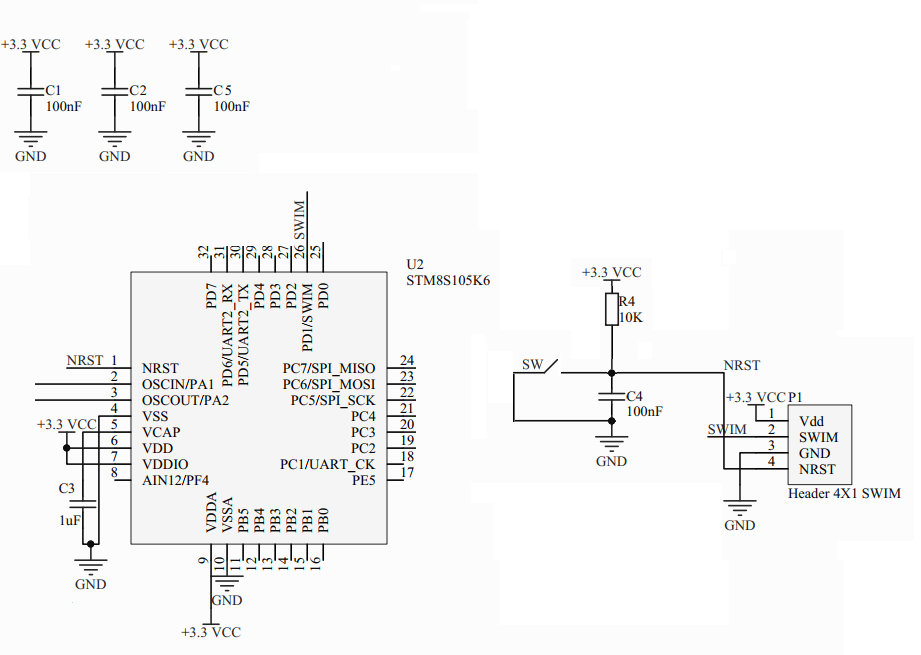
- We look at RM point 7. Power supply, we read . It is written that you need a capacitor connecting the VCAP pin and our 0V power supply. It is also written that you need to look in more detail in DS to a specific MK in the electical characteristics section. For me, this is clause 10.3.1 of the VCAP external capasitor with reference to Table 18 where the nominal value is 470 - 3300 nF. I took 1 mF (in circuit C3). (why you need it, I hope you read it yourself in RM)
- Ibid. In DS in clause 10.3.8. Reset pin characteristics we find the value of the capacitor 0.1mF (on the circuit C4). Resistor R4 with a nominal value of 10 kOhm is used in debug boards and various application notes, although inside the MK there is already a pull-up resistor with a nominal value of 30 to 80 kOhm (if you believe the same DS). In parallel to the capacitor C4 we put our reset button. Such a reset pattern can be seen, for example, in the Desighn note DN0005.
- Also, ST loves to add 100nF power capacitors to the debug boards, in the number of N pins connected to +1 power. The diagram shows only C1, C2 and C5 3 pieces, and I did not solder them to the board, but you understood the meaning. It will work on the table without them, but in real commercial development it is better to take care of this matter when breeding the device board.
- Unsolve SWIM programming connector (I make from PLS-1x40)
I got such a miracle:
- Buying a finished board (which does not save you from working with a soldering iron)Great, cool, I like it. So many people do.
It is worth familiarizing with the configuration of the board, if it is a board from ST, then it is immediately with the programmer and is connected with a USB type B cable. The ST site will have a diagram on the product page. The board will have buttons, LEDs, tweeters, capacitive buttons and other delights with which you can play.
If the board is Chinese, then often boards without a programmer, you will need a programmer.
Silkscreens of the names of the conclusions are better not to believe and double-check comparing with DS.
I do not consider working with contact breadboards because I do not use it.
Plus I need a programmer, I have a Chinese ST-Link V2. Able to program and STM8 and STM32.
3. Choosing an IDE
For me, the question of choice is not yet relevant, I work in the IAR for STM8, because it made a project on which I am currently working, for the same reason the old version.
We go to the site iar.com , in the search we type the model of our MK.
Download the IAR Embedded Workbench for STM8, select the size-limited evaluation when installing, and put up with a limit of 8 KB of code. Or buy. There are hacked versions on resources prohibited on the territory of the Russian Federation, but it is not suitable for commercial projects.
Installation instructions are in the installer or in Google.
I am using version 6.5.3.2581.
Install the environment, along with it the driver for the programmer.
4. Creating a project
Go to the IDE, go to Project -> Create new project -> C ++
Click OK, select the directory (preferably without Cyrillic and spaces), select the name (without spaces and Cyrillic).
We go to the root folder of our IDE and find the inc folder, for me the path:
C:\Program Files (x86)\IAR Systems\Embedded Workbench 6.5\stm8\inc
Among the iostm8 header files we find our MK model, for me:
iostm8s105k6.h
We connect it at the very beginning and add an infinite loop.
Result:
#include<iostm8s105k6.h> // int main() { while(1){ // } return 0; }
In the menu Project -> Options -> General Options in the column Device select your MK.
In Project -> Options -> Debugger in the column Driver select ST-LINK.
Find the Download and Debug button on the toolbar.
At the first compilation, the environment will ask you to select the name of the .eww file. (I name the same as the project.)
At the bottom of the Debug Log window should be messages that:
- Preprocessor for STM8 - preprocessor started
- Debugger for STM8 - debugger started
- Connected to STM8 SWIM Debugging system - connected to MK
- Loaded debugee - firmware download has occurred
- Target reset - a reset has occurred
We are in debug mode, but the program is paused.
In the same place on the toolbar we find and press the Go button.
We launched MK in debug mode.
Click Stop debugging, debugging stops, but the MK is powered by the programmer and then runs the program, namely, it spins an endless loop and does nothing.
Summary
The result was a brief overview and an introduction to programming the STM8S series of MKs without programming itself. It turned out only the basis for work, from this usually everything starts - with the assembly of the layout.
I don’t see the point in more detail.
In many articles, after the introduction, literally after a couple of lines, LEDs blink, which I do not understand.
How accomplished the goals can be judged by whether the beginner managed to do something on their own, using the information I proposed. (indicator window Debug log)
Thanks for your attention.
All Articles