TinyFL - microcontroller flashlight driver
Hi Habr!
I want to tell a story about how I got a Chinese headlamp on the Cree XM-L LED and what happened to it next.
Background
Once upon a time, I ordered a flashlight with a bright LED from one Chinese site. The flashlight turned out to be quite ergonomic (although it could be easier), but its driver left much to be desired.
It shone brightly enough, but the driver had only 3 modes - very bright, bright and strobe, switching between which was done at the touch of a button. In order to simply turn the flashlight on and off, it was necessary to sort through these 3 modes each time. In addition, this flashlight, when turned on, discharged the battery to the last - so a couple of my 18650 cans went into deep discharge.
All this was inconvenient and annoying, so at some point I decided to make my driver for it, which will be the further story.
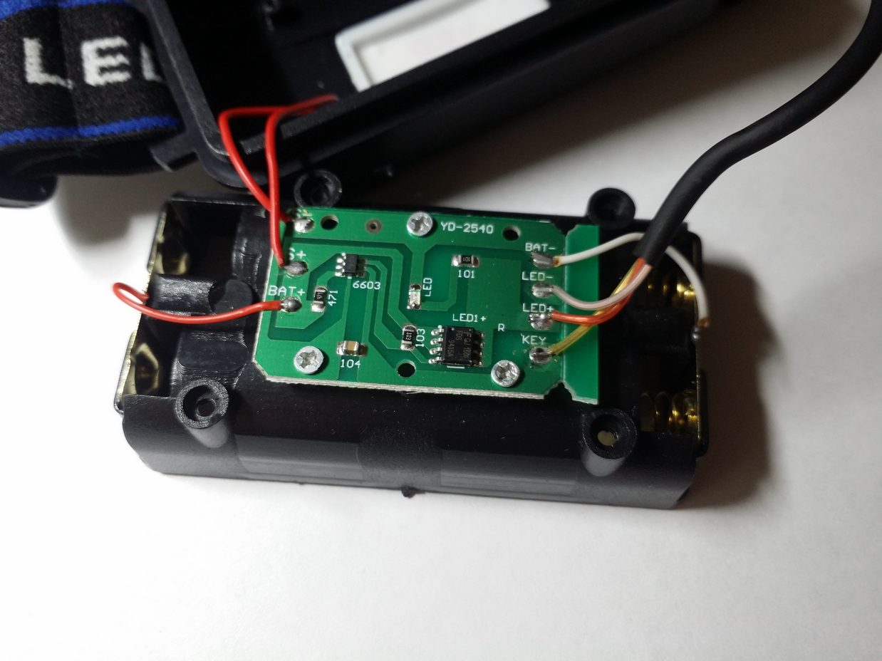
Here's a flashlight, probably many have dealt with similar

It looks like the original driver
Technical task
As you know, in order to achieve a good result, any development should have good technical specifications, so I will try to formulate it for myself. So, the driver should:
- To be able to turn on / off by a short press of a button (a button without fixing). Perhaps this is the main reason why all this started.
- Have a smooth (stepless) brightness control, from the brightest - "turbo" to "moonlight" when the diode is barely lit. The brightness should change evenly.
- Remember the set brightness for the time off.
- Monitor the battery charge, warning when it is almost discharged (about 3.3V) and turning off when it is completely discharged (about 2.9V). For different batteries, these parameters may be different. Accordingly, the operating voltage should be in the range 2.7 ~ 4.5V.
- Have 2 special modes - emergency beacon and strobe (well, why not?)
- To be able to turn on / off the rear LED (this is true when riding a bicycle at night, it turns out something like a marker light).
- Have protection against reverse polarity and static electricity. Not necessarily, but it will be a nice addition, because in the dark you can mistakenly put the battery on the wrong side.
- Be smaller than the original driver in size, but have the same footprint. The Chinese driver is simply huge, making it bigger will not be easy.
Well, if the flashlight is modded, why not build in a charger with a micro-USB connector? I always have such a cable and USB charging at hand, and I have to look for a native power supply.
Iron
I have some experience with Arduino, so it was decided to make a driver on the AVR family MK. They are widely available, easy to program, and have low power (sleep) modes.
The Attiny13a microcontroller was chosen as the driver’s “brain” - it is one of the cheapest Atmel MCs (now absorbed by Microchip), it has everything on board - a GPIO for connecting a button and an LED, a timer for generating a PWM signal, an ADC for measuring voltage and EEPROM to save parameters. Only 1 KB of flash memory is available (but how much is needed for a flashlight), as well as 64 B RAM and the same amount of EEPROM.
Attiny13 is available in several housing options, in particular in DIP-8, which can be inserted directly into a regular breadboard in 2.54 mm increments.
Since only 3 wires go from the back to the head of the flashlight, the button is forced to short to ground (about the impossibility of shorting to plus - later), you will have to switch the LED in the plus - which means you need a P-channel pole. I took AO3401 as such a transistor, but you can take SI2323, it is more expensive, but has less open channel resistance (40 mOhm, whereas AO3401 has 60 mOhm, at 4.5 V), therefore, the driver will heat up less.
Well, from words to action, I am collecting on a breadboard a preliminary version
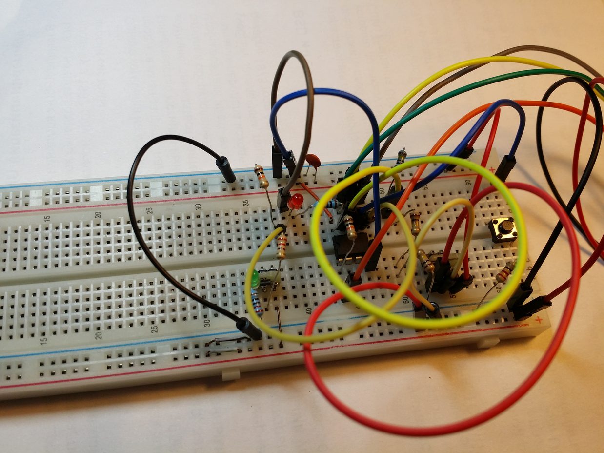
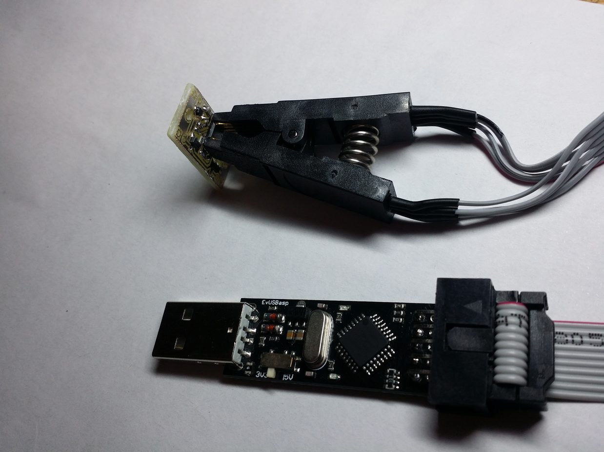
It is currently powered directly from the programmer, with a voltage of 5 V (actually less due to losses in the USB cable). Instead of the LED, the XM-L has stuck a regular LED on the legs and put a weak transistor with a high threshold voltage.
Then, in the Altium Designer program, a diagram was drawn, which I supplemented with protection against reverse polarity and ESD.
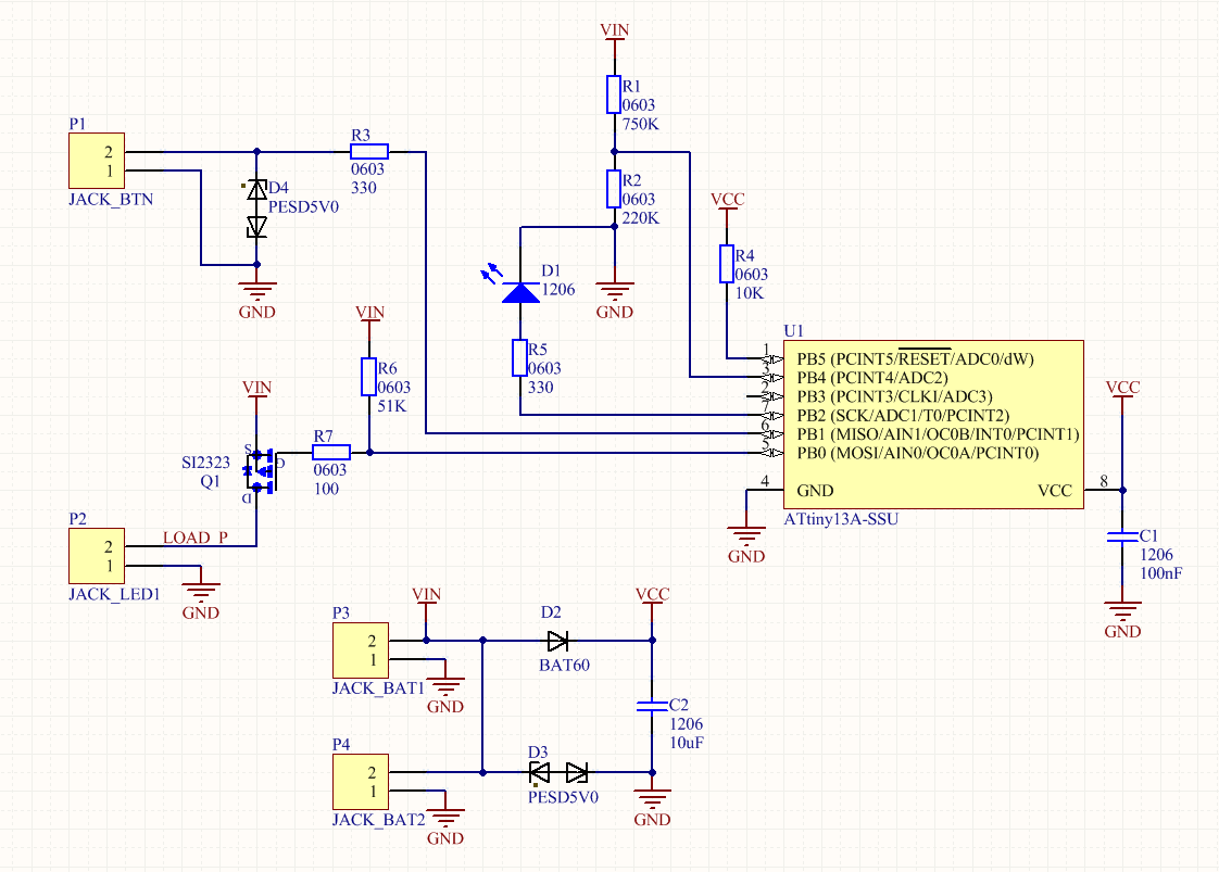
Prerequisites:
U1 - Attiny13a microcontroller in 8S1 package (SSU index)
C1 - decoupling capacitor for power supply of the microcontroller, should be in the region of 0.1 microfarads, case 1206 or 0805, temperature coefficient X7R
R1-R2 is a resistor divider for measuring battery voltage, any ratings can be set, here the main ratio (750K / 220K, division ratio 4.41) and leakage current, which will be greater if the ratings are increased (at current it is about 4 μA). Since an internal ION is used (1.1 V, according to the datasheet it can be between 1.0 V - 1.2 V), the maximum voltage at the output of the divider should not be more than 1 V. With a divider 750/220, the maximum allowable voltage at the input of the divider will be 4.41 V, which more than enough for all types of lithium batteries.
I calculated the divider using this calculator .
R3 - protects the output of the microcontroller port from short circuit (if suddenly PB1 is pulled to VCC, a large current will flow through the pin and the MC may burn out)
R4 - pulling RESET MK to power, without it, reboots from pickups are possible.
Q1 - P-channel field effect transistor in the SOT-23 package, I installed the AO3401, but any other with a suitable pinout (for example, SI2323)
R7 is a current limiting gate resistor. Since the gate of the transistor has a certain capacity, when charging this capacity, a large current can pass through the pin and the pin may fail. You can set it in the region of 100-220 Ohms (it should not be anymore, the transistor will begin to be in a half-closed state for a long time, and, as a result, it will get hotter).
R6 is a resistor for tightening the shutter to power. In case PB0 goes into a high-impedance state, logic 1 will be established through this resistor on gate Q1 and the transistor will be closed. This can happen due to an error in the code or in programming mode.
D2 - "locking" diode - allows for voltage "sagging" (when the LED turns on for a short period to full brightness) to feed the MK from the capacitor for a while, it also protects against reverse polarity.
You can put any Schottky diode in the SOD323 package with a minimum voltage drop, I put BAT60.
Initially, protection against reverse polarity of the power supply was made on the field effect transistor (this can be seen on the boards made by loot). An unpleasant feature came out after wiring - when the load was turned on, a voltage drop occurred and the MK rebooted, since the field worker does not limit the current in the opposite direction. At first I soldered a 200 uF electrolytic capacitor between VCC and GND, but I did not like this solution because of its size. I had to solder the transistor and put a diode in its place, since SOT-23 and SOD-323 have similar dimensions.
Total, in the circuit there are only 10 components that are required for installation.
Optional components:
R5 and D1 are responsible for the backlight (LED2). The minimum rating of R5 is 100 ohms. The higher the rating, the weaker the rear LED is lit (it turns on in constant mode, without PWM). D1 - any LED in the case 1206, I put green, because visually they are brighter at the same currents than others.
D3 and D4 are protective diodes (TVS), I used PESD5V0 (5.0V) in the SOD323 package. D3 protects against overvoltage by power, D4 - by a button. If the button is covered by a membrane, then there is no special meaning in it. It is probably worthwhile to use bi-directional protective diodes, otherwise, when the polarity is reversed, current will flow through them and they will burn out (see CVC of a bi-directional protective diode).
C2 - a tantalum capacitor in case A (similar to 1206), it makes sense to set it during unstable operation of the driver (the supply voltage may be squeezed at high switching currents of the LED)
All resistors of size 0603 (for me, this is an adequate limit for manual soldering)
Everything is clear with the components, you can make a printed circuit board according to the above scheme.
The first thing to do is to build a 3D model of the future board, along with the holes - IMHO, in Altium Designer this is the most convenient way to determine the geometry of the PCB.
I measured the dimensions of the old driver and its mounting holes - the board should be attached to them, but have smaller dimensions (for versatility, suddenly you have to build it somewhere else).
A reasonable minimum here turned out somewhere around 25x12.5mm (aspect ratio 2: 1) with two holes with a diameter of 2mm for attaching to the lamp housing with native screws.
I made a 3D model in SolidWorks, then exported to Altium Designer as STEP.
Then I placed the components on the board, made the contacts in the corners (it is more convenient and easier to solder the ground), Attiny13 put in the center, the transistor closer to the LED contacts.
I spread the power tracks, placed the remaining components as it turned out and parted the signal tracks. For convenience of connecting the memory, I brought out separate contacts for it, which duplicate the battery contacts.
I made all the wiring (with the exception of one jumper) on the top layer - in order to be able to make a board at home with LUT.
The minimum width of the signal paths is 0.254 mm / 10 mil, the power ones have a maximum width where possible.
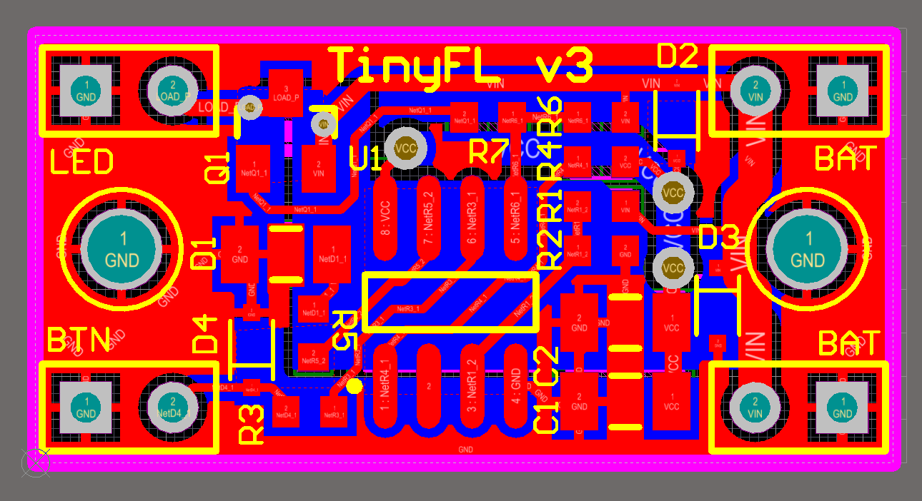
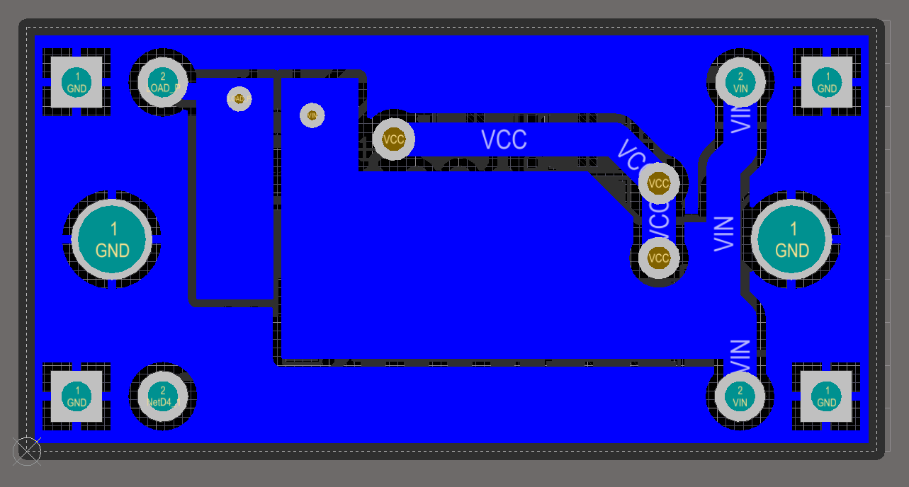
This is how the wired board looks in Altium Designer:
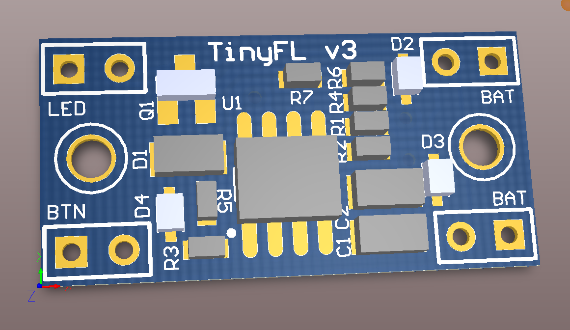
Altium Designer has the opportunity to see how the board will look in 3D (for this you need models for all components, some of which you had to build yourself).
Perhaps someone here will say that 3D mode is not needed for the tracer, but for me personally it is a convenient function that facilitates the placement of components for the convenience of soldering.
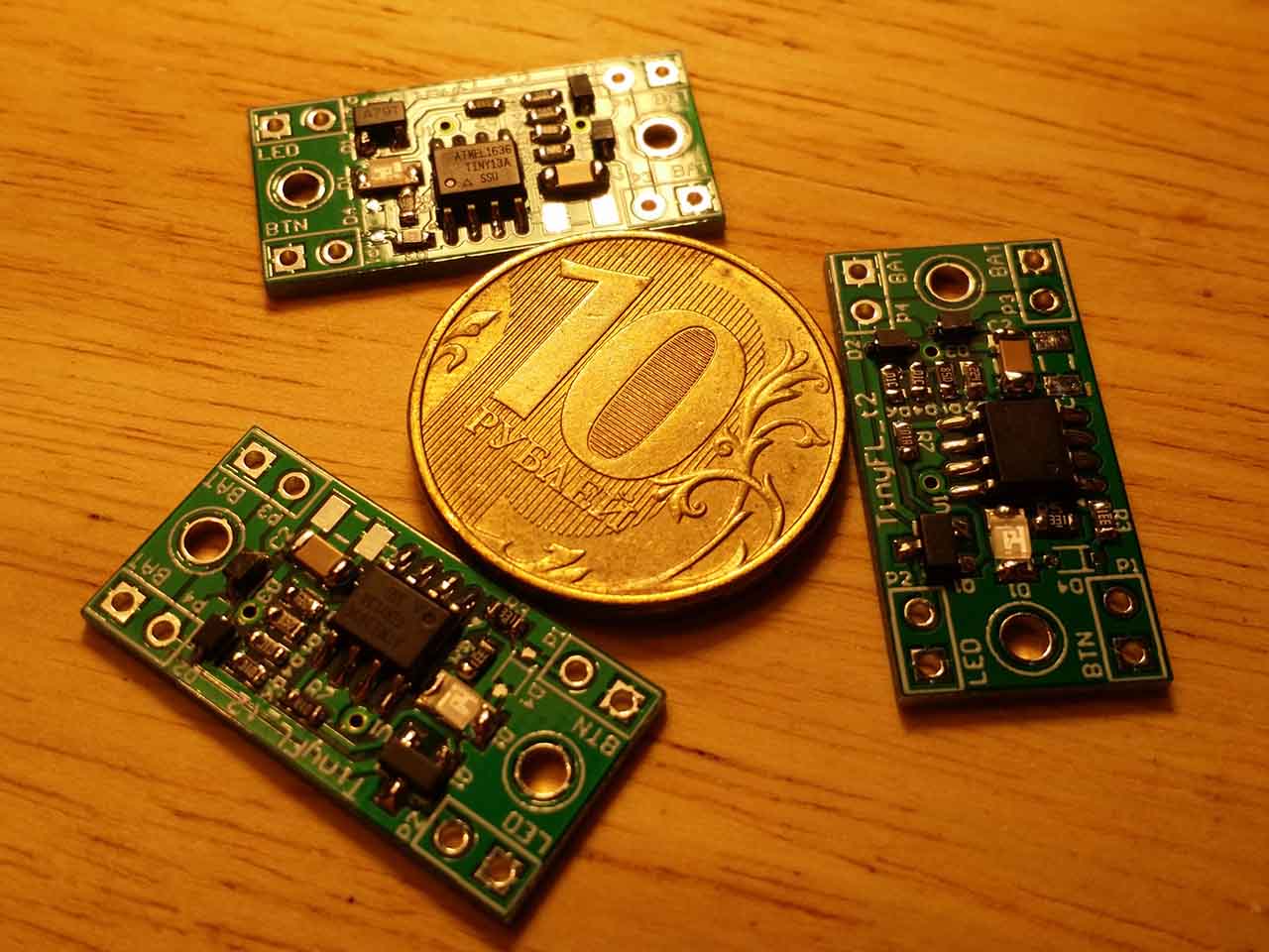
At the time of writing, 3 versions of the board were made - the first for LUT, the second for industrial manufacturing and the 3rd, final with some corrections.
Board making
Homemade way
LUT - laser-ironing technology, a method for producing circuit boards using etching on a mask obtained by converting toner from paper to copper. This method is great for simple single-sided boards such as this driver.
The network has a lot of articles on this technology, so I will not go into details, but only briefly tell you how I do it.
First you need to prepare a template that will be printed on thermal paper. I export the top_layer layer to PDF, I get a vector image.
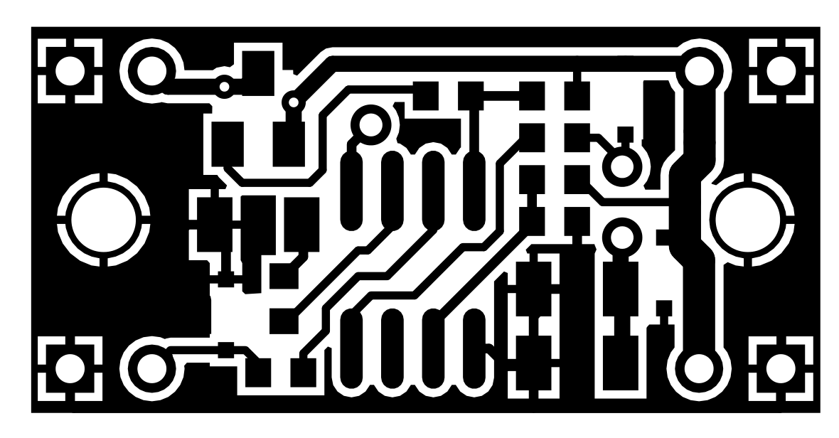
Since the board is small, it makes sense to take a piece of PCB with dimensions several times larger and do what the industry calls paneling.
For these purposes, CorelDraw is very convenient, but you can use any other vector editor.
I place copies of templates on the document, I make 0.5-1mm gaps between the boards (it depends on the separation method, more on that later), the boards should be located symmetrically - otherwise it will be difficult to separate them.
I select a piece of one-sided PCB with dimensions slightly larger than the assembled panel, clean and degrease (I prefer to rub with an eraser and then with alcohol). I print a template for etching on thermal paper (here it is important not to forget to mirror the template).
With the help of an iron and patience, gently stroking on paper, I translate it to textolite. I wait until it cools down and carefully peel off the paper.
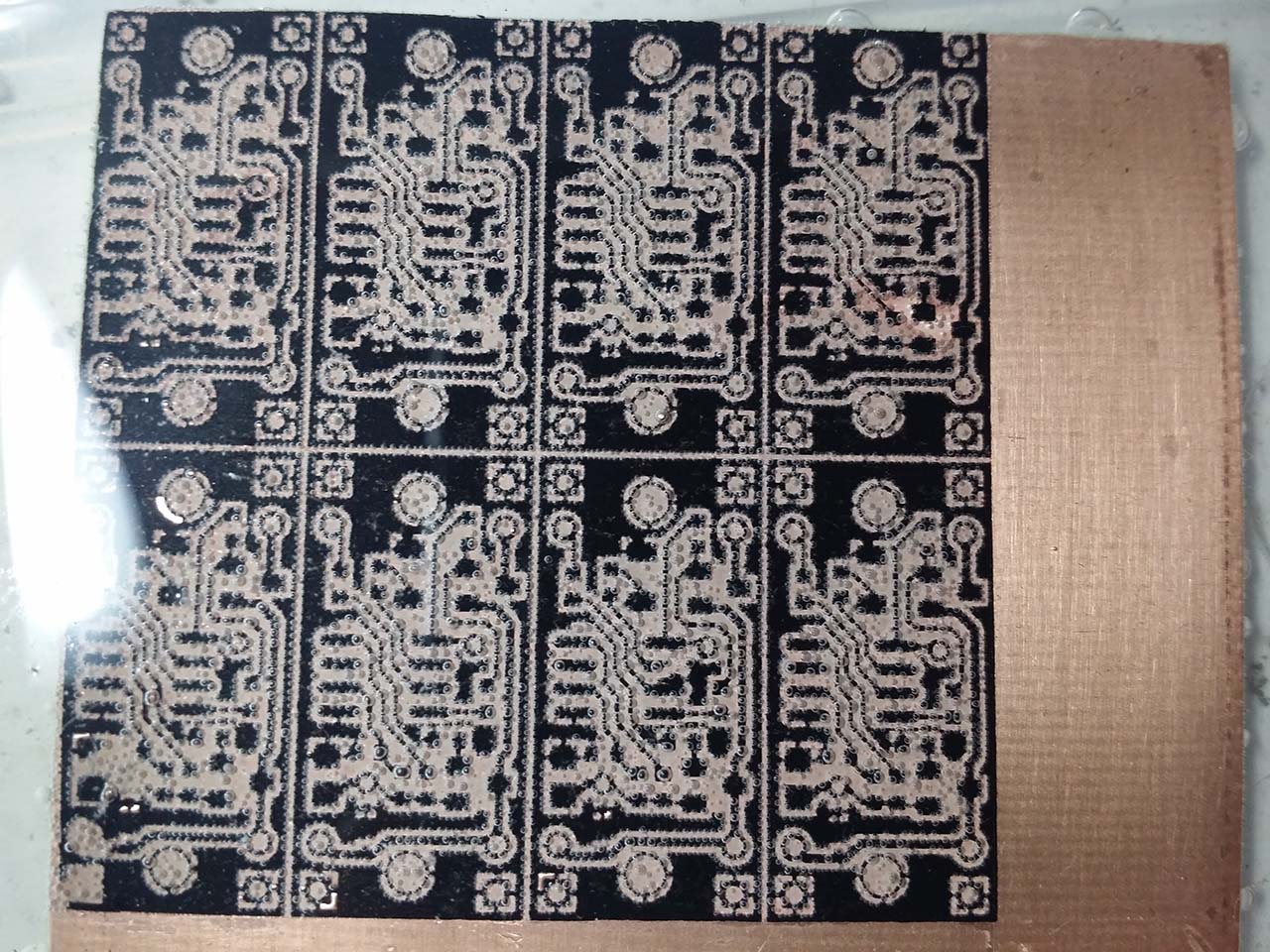
Free areas of copper (not coated with toner) can be varnished or taped (the smaller the area of copper, the faster the etching reaction).
Such is home paneling. A large number of boards can compensate for manufacturing defects - for example, the photo shows the place where the toner exfoliated.

I etch the boards with citric acid in a hydrogen peroxide solution, this is the most affordable way, albeit rather slow.
The proportions are as follows: for 100 ml of peroxide 3% is 30 g of citric acid and about 5 g of salt, all this is mixed and poured into a container with textolite.
Warming the solution will speed up the reaction, but may cause the toner to peel off.
Unknown chemical magic begins: copper is blistered, and the solution becomes blue.
After some time I take out the etched board and clean it of toner. I can’t wash it off with any solvents, so I remove it mechanically with fine-grained emery paper.
Now it remains to tin the board - this will help with soldering and protect copper from oxidation and facilitate soldering. I prefer tinning with the Rose alloy - this alloy melts at a temperature of about 95 degrees, which allows it to be tinned in boiling water (yes, it may not be the most reliable composition for tinning, but for home-made circuit boards).

After tinning, I drill a board (for contacts I use carbide drills f1.0, for jumpers - f0.7), I drill with a dremel for lack of another tool. I don’t like to cut textolite because of the dust, therefore, after drilling, I cut the boards with an office knife - on both sides I make several cuts in one line, then break it into a cut. This is reminiscent of the V-cut method used in industry, only there is an incision made by a mill.
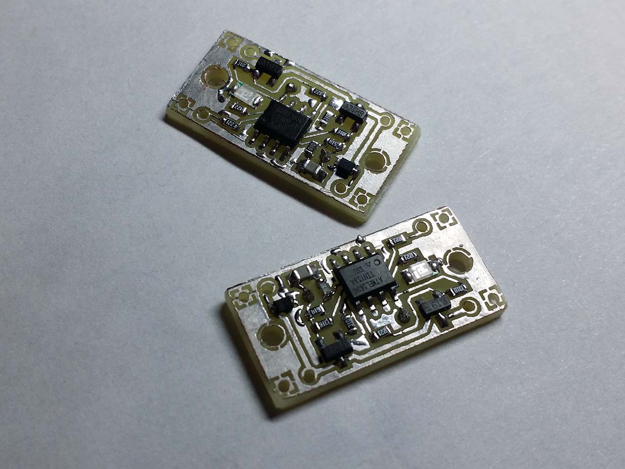
It looks like a board ready for soldering

When the board is ready, you can start wiring the components. First, I solder a trifle (resistors 0603), then everything else. Resistors are adjacent to the MK, so soldering in the reverse order can be problematic. After soldering, I check if there is a short circuit for powering the driver, after which it is already possible to start firmware MK.
Drivers ready to download firmware
Industrial way
LUT is fast and affordable, but the technology has its drawbacks (like almost all “home” PP manufacturing methods). It is problematic to make a double-sided board, the tracks can be etched, and you can only dream of metallizing the holes.
Fortunately, enterprising Chinese have long been offering services for the manufacture of printed circuit boards in an industrial way.
Oddly enough, a Chinese single-layer board will cost more than a two-layer board, so I decided to add a second (bottom) layer to the printed circuit board. Power paths and ground are duplicated on this layer. Also, it became possible to make a heat sink from the transistor (copper polygons on the lower layer), which will allow the driver to work at higher currents.
The bottom layer of the board in Altium Designer
For this project, I decided to order a printed circuit board on the PcbWay website. The site has a convenient calculator for calculating the cost of boards, depending on their parameters, sizes and quantity. After calculating the cost, I downloaded the gerber file created earlier in Altium Designer, the Chinese checked it and the board went to production.
Making a set of 10 TinyFL boards cost me $ 5. When registering a new user, a $ 5 discount is given for the first order, so I only paid for shipping, which also costs somewhere around $ 5.
On this site there is the opportunity to put the project in the public domain, so if someone wants to order these boards, you can simply add this project to the basket.
After a couple of weeks, the same boards came to me, only pretty manufactured industrially. They can only be unzipped and filled in with the firmware.

Program (firmware)
The main difficulty that arose when writing the driver firmware, it is associated with the extremely small size of flash-memory - Attiny13 has only 1024 bytes.
Also, since the brightness change is smooth, a non-trivial task was to uniformly change it - for this we had to do gamma correction.
Driver control algorithm
The driver turns on by a short press on the button, it turns off by it.
The selected brightness mode is stored for the duration of the shutdown.
If during operation you make a double short press of a button (double click), the additional LED will turn on / off.
With a long press during operation, the brightness of the flashlight will gradually change. Repeated long press changes direction (stronger / weaker).
The driver periodically checks the battery voltage, and if it is lower than the set values, warns the user about a discharge, and then turns off to avoid a deep discharge.
- When power is supplied to the MK, peripherals are set up and the MK goes into sleep (if STARTSLEEP is defined). When power is supplied to the driver, both LEDs flash a certain number of times if STARTBLINKS is defined.
- Sleep. Attiny13 falls asleep in power-down mode (this is the most economical mode, according to the datasheet, MK consumption will be ~ 1 μA), from which it can only exit by any interruption. In this case, this is an INT0 interrupt - pressing a button (setting PC1 to logical 0).
On PC1, an internal weak pull-up should be turned on. The ADC and comparator are the main consumers of current from the entire periphery, so they also need to be turned off. During sleep, the contents of the registers and RAM are stored, so the EEPROM is not needed to remember the brightness. - After sleep, the peripherals and PWM turn on and the driver enters an endless cycle in which the button is monitored and the battery voltage is periodically checked.
- If the button is pressed, the time is pressed.
4.1. If the press is short, a double click is expected (if BTN_DBCLICK is defined).
If it was, the additional LED2 switches
If not, go to step 2 (sleep)
4.2. If the press is long (longer than BTN_ONOFF_DELAY) - the brightness control mode is activated. In this mode:
- The direction of change (larger / smaller) is inverted and the% of PWM filling changes while the button is pressed.
- If the maximum / minimum value is reached (RATE_MAX / RATE_MIN), the LED starts flashing;
- If n-flashes have passed (AUXMODES_DELAY) and the button is still pressed, additional mode is activated. There are two such modes - a strobe (turns on for 25 ms, a frequency of 8 Hz) and an emergency beacon (turns on at full brightness for 50 ms, a frequency of 1 Hz). In these modes, the battery charge is not checked, but to exit, you need to hold the button pressed for a while.
- If it is time to check the battery voltage - readings from ADC2 are read, the result is compared with preset values.
- If the value of the ADC is greater than the value of BAT_WARNING - everything is fine
- If less than BAT_WARNING - the user is warned about the discharge, the driver blinks the main LED. The number of flashes will be proportional to the degree of discharge. For example, with default values when fully discharged, the flashlight will flash 5 times.
- If less than BAT_SHUTDOWN - MK goes to step 2 (sleep).
LED brightness control
As you know, the easiest way to control the brightness is to change the PWM duty cycle, while the LED turns on for a while at full brightness, then turns off. Due to the characteristics of the human eye, it seems that the LED shines less brightly than if it was constantly on. Since the LED is connected via a P-channel field effect transistor, to open it, you need to pull the shutter to ground, and to close, on the contrary, to power. The opening time of the transistor with respect to the time of its closed state will correlate with the filling of the PWM.
The variable rate is responsible for the duty cycle of the PWM, 255 rate = 100% PWM.
With a clock frequency of 1.2 MHz and a timer pre-selector of 1, the PWM frequency will be 1200000/256 = 4.7 KHz. Since this is the sound frequency (perceived by the human ear), at some duty cycle, the PWM driver can start to squeak (more precisely, it does not squeak the driver, but the wires, or the batteries). If it interferes, you can increase the operating frequency to 9.6 (CKSEL [1: 0] = 10, CKDIV8 = 1) or 4.8 MHz (CKSEL [1: 0] = 01, CKDIV8 = 1), then the PWM frequency will be 8 or 4 times more, but the power consumption of the MK will also grow proportionally.
Someone believes that the diode needs to be powered by stabilizing the current through it, and in this mode it will quickly fail. Then I agree and say that in my lamp the LED does not connect directly to the driver, and rather long and thin wires go to it, the resistance of which, as well as the internal battery resistance and the driver’s resistance, limit the maximum current in the region of 1.5 A, which 2 times less than the maximum current for this LED (maximum current for Cree XM-L according to the documentation is 3 A).
If you will build a driver, I advise you to measure the current consumption in maximum brightness mode (rate = 255). If the current exceeds the maximum current of your diode, I recommend reducing the RATE_MAX parameter to obtain acceptable values. Although, according to the specification of the SI2323DS transistor, its maximum current exceeds 4A, it is better not to exceed the threshold of 2A, otherwise the driver will need cooling.
Gamma correction
The human eye perceives the brightness of objects non-linearly. In the case of this driver, the difference between 5-10% PWM will be perceived as a multiple increase in brightness, while the difference between 75-100% will be almost invisible to the eye. If you increase the brightness of the LED evenly, at a speed of n percent per second, it will seem that at the beginning the brightness increases very quickly from zero to average, then it increases very slowly from mid to maximum.
This is very inconvenient, and to compensate for this effect, we had to make a simplified gamma correction algorithm. Its essence is that the brightness change step increases from 1 at minimum PWM values to 12 at maximum values. In a graphical representation, it looks like a curve whose points are stored in the rate_step_array array. Thus, it seems that the brightness changes uniformly throughout the range.
Battery Voltage Monitoring
Every n-seconds (the BAT_PERIOD parameter is responsible for the interval in milliseconds), the battery voltage is measured. The positive contact of the battery, which connects to the VIN and falls on the resistor divider R1-R2, to the midpoint of which the pin PB4 is connected (it is ADC2 for the ADC multiplexer).
, , Vref, 1.1 . — , (, 1.1 1023 255, 8- ). , 6 , 255 1.1 , 4.33 ( 4.03), .
, . BAT_WARNING ( , — BAT_INFO_STEP, ), BAT_SHUTDOWN .
, .. , .
, , . , 4.03 R1 = 1M R2 = 330, R = 1330K 4 = 3 .
() 1 . , , ( - — ).
, Arduino C/C++.
, (defines) flashlight.h.
Atmel Studio – , Arduino IDE, .
(flashlight.atsln) . — flashlight.h (), flashlight.cpp .
— .
F7, ( , , ). debug flashlight.hex, .
, , . XM-L 3 , , SI2323 4 , - .
, RATE_MAX (#define RATE_MAX xx).
, , , .
, . . -, ( 1-5%), -, 1.0 1.2 .
, — (BAT_WARNING BAT_SHUTDOWN), . , .
BAT_PERIOD 1000 ( ) . , BAT_WARNING .
, EEPROM.
, . .

, , . (TP4056), , ( , , ).
, . . , , , . , .
. , .
( 4.04 ):
- —
- : 0.60
- : 0.30
- : 0.28
( 4.0 ):
- 4 , - . .
- , "" — 5-7 , , 18650 2500 *, 20 . - 1.2-1.5 ( 1.2 ).
- , "" — 1.5 , . , .
- — 80 , 30 .
- — 0.35 , 6 .
, 100 (60 Attiny13, ~40 ). , — , 10 .
300 10 ( ), .
- .
Conclusion
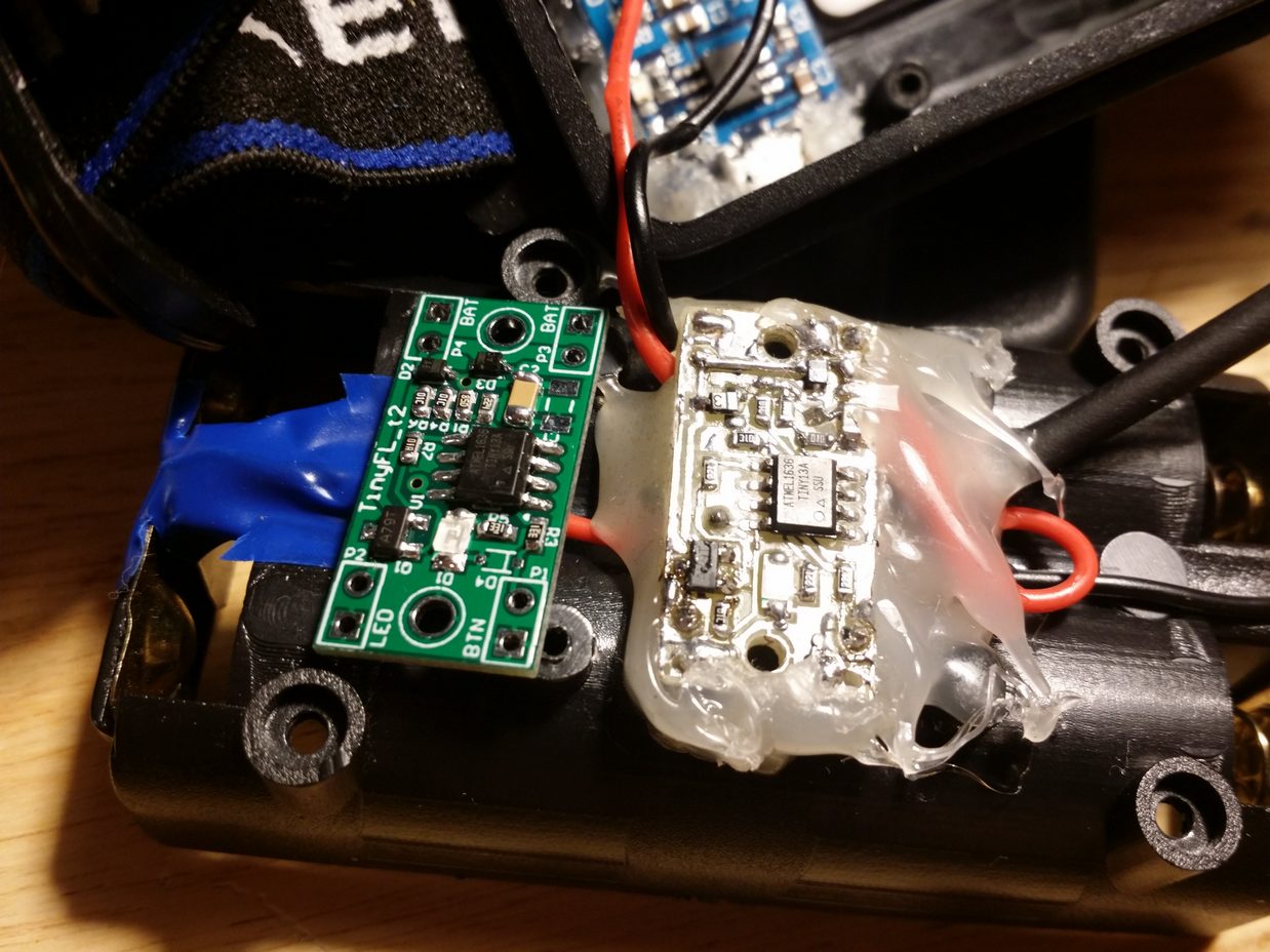
The Chinese flashlight has become much more convenient, although now I have complaints about its mechanics - the front part is too heavy, and the focus is not really needed.
In the future I plan to make a version of this driver for flashlights with a power button (with fixation). True, I am confused by the abundance of such projects. Do you think it's worth doing another one?
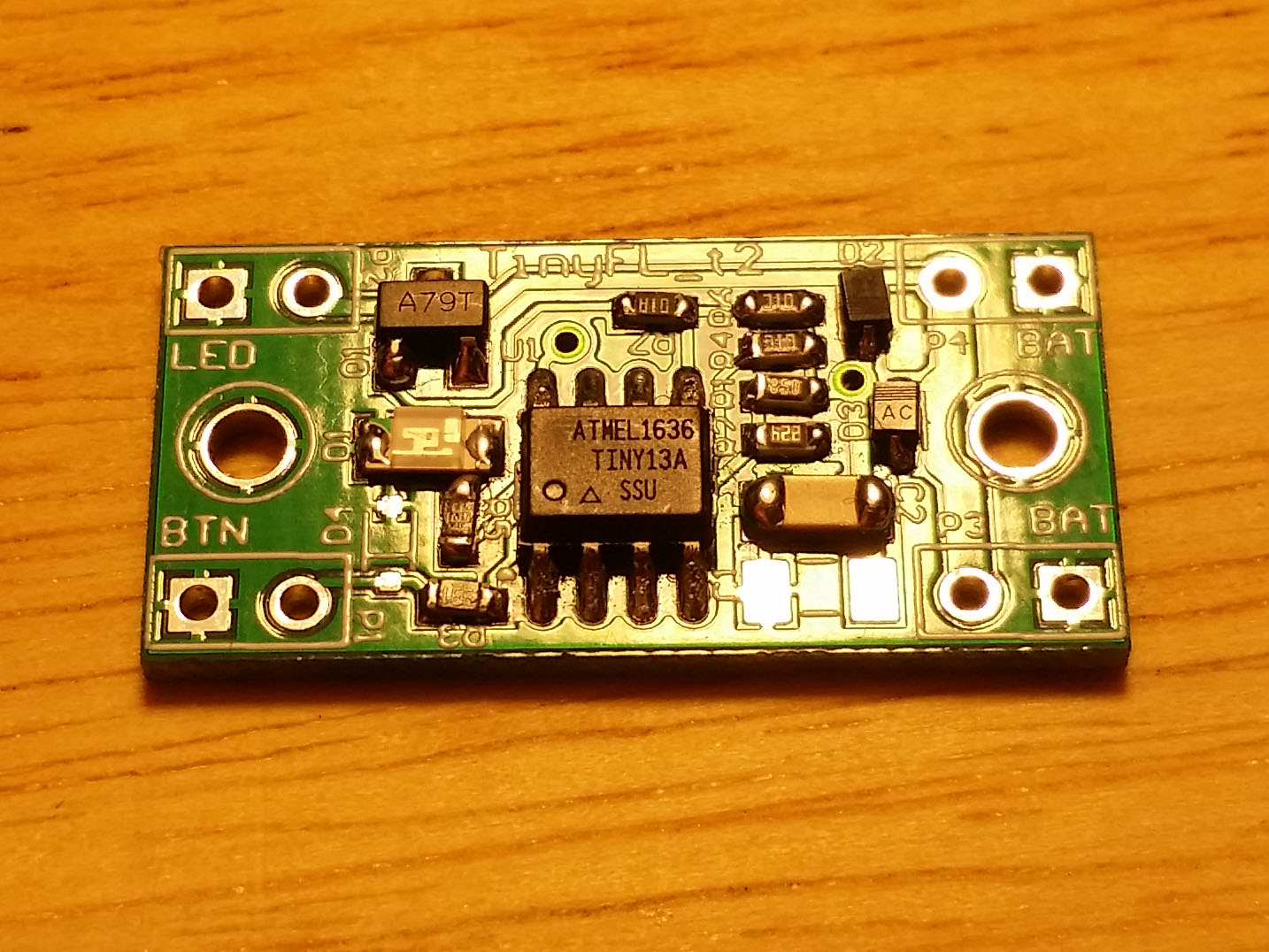
Close-up driver (version 2_t)
The source code of the firmware, the circuit, and the wiring of the board are now on the github, you can download it here: https://github.com/madcatdev/tinyfl_t
All Articles