Reverse engineering electric cornice AM82TV
I have a couple of Akko electric curtain rods - AM82TV. This model stands out from its brethren with the most complete set of management interfaces. The curtains can be controlled by radio, there are “dry contacts”, phase-by-phase control (by shorting the control wires to the network). There is an RS485 interface - this is if you want to connect the curtains to the “smart home”. You can also open / close the curtains simply by pulling them with your hand in the desired direction. “Out of the box” is missing, perhaps, only the web-based interface, well, and MQTT.
I have long had electric curtain rods working reliably, but from time to time a desire began to appear to disassemble them - out of curiosity to see what is inside and whether it is possible to put an ESP8266 (or ESP32) into it in order to add the missing. You can, of course, connect everything from the outside, but it is better if the appearance remains the same and everything is hidden inside.
Do not repair what is not broken - this is not about me. At first I tried to drive away bad ideas from myself, but over time, the itching intensified and now, the moment came when it was already impossible to fight it. I took the motor off the eaves and took it apart. The initial inspection was to answer two questions: is there room for the ESP8266 and is it possible to use the built-in power supply. Everything was sorted out simply. It is enough to unscrew a few screws from the ends of the motor. The only thing is that the slots of the screws are not made with a screwdriver, but with a torx hex key. After that, you can extract the contents - a collector motor in one housing with a gearbox and a motor shaft sensor, a 24-volt power supply and a control board.
There is a place for ESP, the power supply is designed for a powerful motor and will not notice a small additional load. I began to consider the control board and thoughts about ESP began to fade into the background - the atmega168 microcontroller was the heart of the board. If there were no contacts on the board for installing the ISP (microcontroller in-circuit programming interface) connector, this would not stop me, but they were there. So that you understand me correctly, I'm not a fan of avr at all. I do not have a programmer and I have not written a single line of code for atmega microcontrollers. I urgently needed a programmer to try to read the firmware, but it was in the evening and there was no way to buy something in the store right now. In order not to wait until morning, I assembled the Gromov programmer. Then he soldered the ISP connector on the control board, connected the programmer and tried to read the firmware - and it was counted.
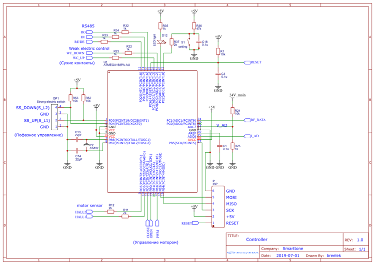
Trying to understand something in the firmware of the microcontroller without understanding the circuit diagram is impossible. Therefore, on a printed circuit board, I restored the circuit. I don’t often have to draw diagrams. In order not to draw the elements that are on the board, but not in the standard library, I drew a diagram in easyeda. Yes, it turns out not according to GOST (but the microcontroller is drawn as in the documentation, which is convenient). A fragment is enough for understanding:
Hereinafter, most of the images are clickable.
If you wish, you can familiarize yourself with the full scheme .
After that, I was ready to research the firmware. Just translating machine codes into assembly mnemonics is not enough for analysis. You need to see the status of the registers and memory at any point in the program. Unfortunately, debugging on the microcontroller itself is not possible with atmega168, but you can load the firmware into the simulator. Not too convenient if you want to “feel” the real hardware of the microcontroller strapping, but let’s get by with what it is. I did not install Atmel Studio 7. I decided that a more compact AVR Studio 4 would be enough. In principle, one Studio is enough for analysis, but it is possible to shift some of the routine operations to other software. In March, a reverse engineering tool, Ghidra, was published. I needed a reason, some practical task, to get to know him. This is just an opportunity. Each instrument individually - AVR Studio 4 and Ghidra I got a little bit buggy. AVR Studio, with several nested subprogram transitions, might suddenly stop displaying the correct transition addresses in commands (the address became zero). Ghidra sometimes went astray in its indexing analysis. But the use of both tools at once made it possible to quickly identify the cause of these oddities.
Digging aimlessly in the firmware is not too interesting. It is better if there is any specific task. On the off, curious may be the analysis of the exchange protocol for RS485 and the control protocol over the air. I decided to delve into the radio protocol.
Once upon a time, I had already taken a signal transmitted by a radio remote control and analyzed it.
The radio channel is one-way. The motor is only able to receive a signal and does not confirm receipt of a command. It is impossible to interrogate the state of the electric cornice over the air. At the physical level, there is only a radio signal receiver. There is no transmitter in the motor. The signal is transmitted by the radio remote control at a frequency of 433.92 MHz. Coded by amplitude manipulation. The team consists of a special form start bit, address + channel and the command itself. Graphically, the entire signal can be represented as follows:
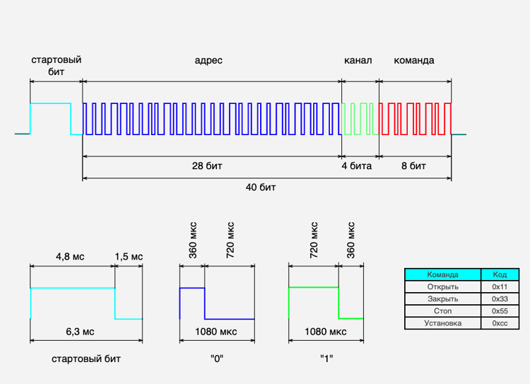
A channel can be considered as part of an address. If you transmit a command on channel zero, it will be executed by all devices with a given address, but with different channels. It is convenient if you need to transfer the command immediately to the group of electric curtain rods.
Read more about the radio protocol .
Analyzing how the remote control transmits commands, I already knew the codes of the four teams. Not too much, when compared with the possibilities of controlling the electric curtain via RS485. I wanted to make sure that all the teams were identified and that there were no “Easter eggs” or service teams.
The analysis approach is simple. The circuit diagram shows which ports of the microcontroller are connected to physical devices. The firmware file is parsed by Ghidra. This is convenient - many routine operations are performed automatically. After analyzing the operation of a particular code fragment or subprogram, it is given a meaningful name. Further code snippets and screenshots I will bring it from Ghidra. When dull, run the code in the simulator. In especially complicated situations, you have to draw pictures.
To ensure that the names of the atmega168 peripheral registers are displayed correctly during disassembly, I corrected the avr8.pspec file. In a good way, it would be necessary to create a file with a different name, but I did not need this file in its original form and I corrected the one that was.
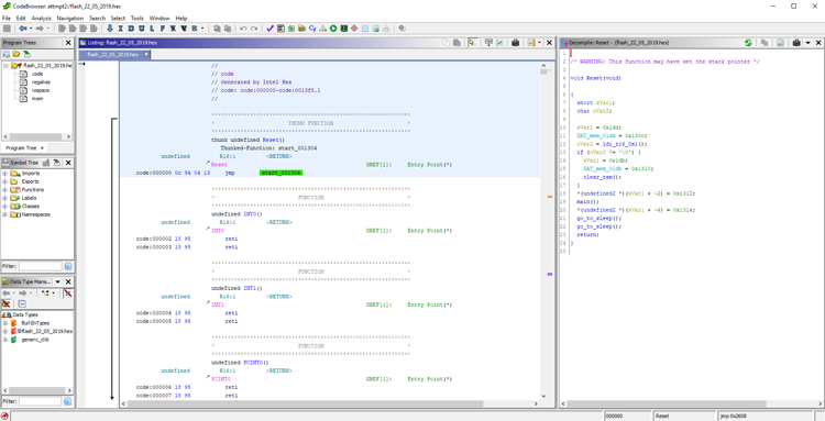
Firmware starts with interrupt vectors. The first is the transition vector to the beginning of the program. It looks like this:
Most interrupts are not used. If for some reason such an interruption occurs, a return command will be executed immediately. In addition to processing interrupts for reset, interruptions for overflowing Timer 0, completion of reception, and readiness to transmit the next data byte to USART are also processed. RS485 exchange is not of interest to us now, but the timer overflow needs to be reviewed.
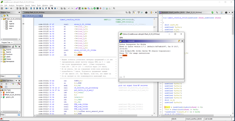
Of course, before the timer interrupt is enabled, the timer itself must be configured. I did not begin to search in the disassembled code for the place where the initialization takes place. In the simulator, I set a breakpoint at address 0x1fc - this is the address recorded in the interrupt handler. I started the program, got a spike and just looked at what was written into the registers. lock select for timr0 is set to clk / 8. With quartz on an 8 MHz board, pulses with a frequency of 1 MHz arrive at the timer.
Start of the interrupt handler:
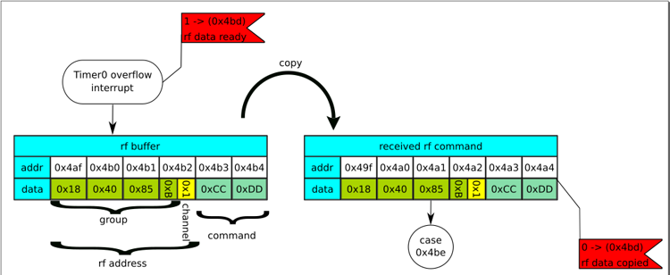
The timer overflows every 107 μs. Among other things, the interrupt handler processes the signal from the output of the radio signal receiver. If the signal passes the test successfully, the received data is written to the buffer at 0x4af. The buffer size is 6 bytes. This is one byte more than necessary to receive four bytes of the address + channel and command byte. Perhaps the sixth byte of the radio protocol was intended for the checksum, but atrophied. Sometimes it happens. Perhaps intended for data supplementing some of the commands. In the RS485 electric cornice control protocol, there is a command to partially close the curtains. In this case, an additional byte is transmitted with data on the percentage of closure. A similar team could exist in the radio protocol. The main program is informed about data readiness by setting a flag - a unit is written at 0x4bd.
This completes the analysis of interruptions and proceeds to the main program.
The graph of functions when navigating to the address 0x1304 is concise and simple:
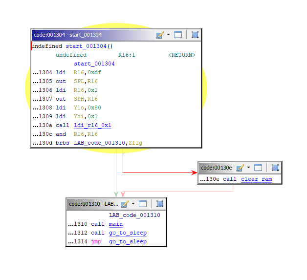
We need to in the “main”. We have already analyzed the interruptions and understand that if for some reason we suddenly return from main and get into “go_to_sleep”, then this dream will turn out to be lethargic - the electric curtain will stop doing something useful. Probably, when writing the firmware, a ready-made template was used and artifacts remained after it.
In main, we need to find the place where the 0x4af buffer is accessed. You won’t have to search for a long time. Literally after a few commands, a subroutine is called, starting with the address 0x11b3, where this buffer is copied and processed.
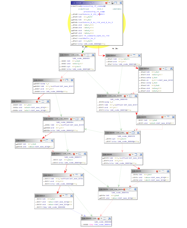
Graph of the functions of the rf_signal_buffer_processing (0x11b3) procedure:

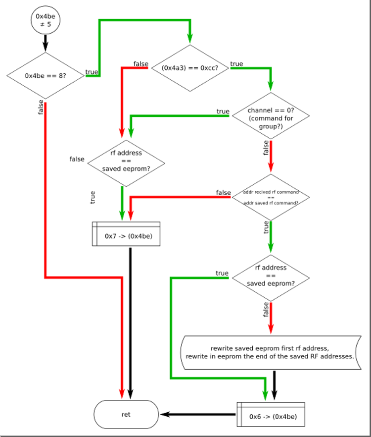
This is exactly the place we need, but it looks a bit complicated. To understand, I began to draw pictures. Something like a flowchart.
The first thing that happens here is that the data from the 0x4af buffer is copied to the new address - 0x49f and the 0x4bd flag is reset:
The following snippet is the most interesting:
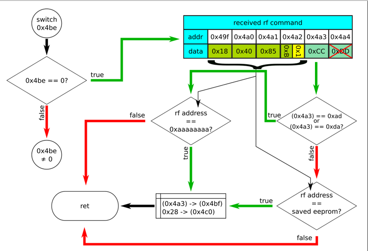
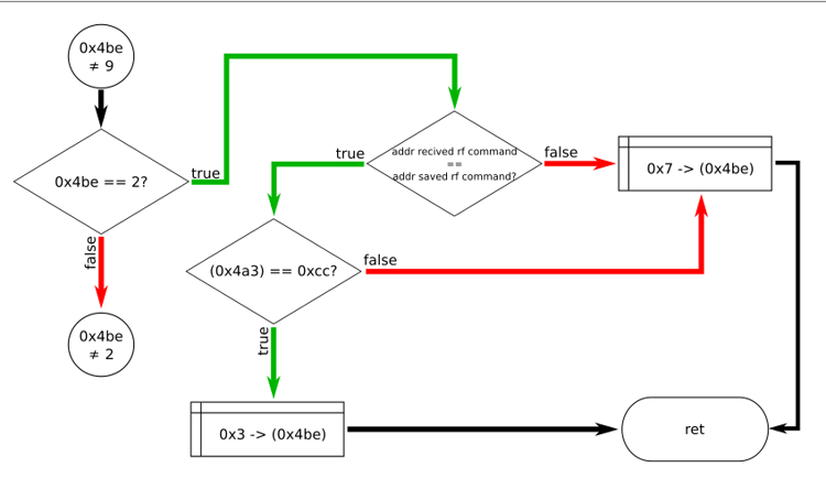
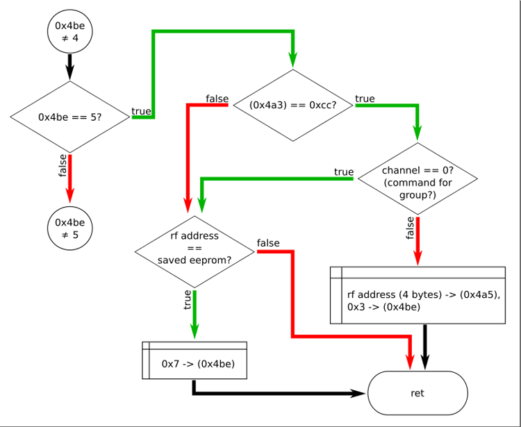
In fact, this is the entire verification of the command received over the air. While this is not obvious, but further analysis showed that the transition to the following branches is the processing of the following radio commands if the 0xcc command was received before that - switching to the settings mode. I was interested in the new codes of the teams themselves. Is there anything besides the command codes 0x11, 0x33, 0x55 and 0xcc.
Neither here nor further was I able to find the processing of the last - sixth byte of the command. In the figure, it is crossed out in red. So all commands consist of five bytes. At least in the firmware of the AM82TV.
The first thing we see is checking the fifth byte of the buffer - the code of the command itself. Here, it seems, there were new command codes - 0xad and 0xda. A command from the buffer passes the test successfully if the address field matches one of the addresses already recorded in eeprom, or if the command code is 0xad, or 0xda and the address field == 0xaaaaaaaa.
Well, we will consider that the next test we successfully passed. Now the command code is located at 0x4bf. We need to find how the contents of this byte are processed. There are several ways to do this. The simplest is a text search on disassembled code in Ghidra. It remains to see exactly where the contents of this byte are read. This is not a guaranteed way to find all the calls, but in this particular case it will work. So, first, we will see a byte reading in the procedure starting at 0x1262:
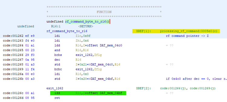
The appeal to which comes from a single place - a team located at 0x5e0.
Function graph:
It’s a pity, but all the command codes, except for the already known ones: 0x11, 0x33, 0x55 and 0xcc are discarded in this procedure. Even the codes 0xad and 0xda found in the previous step. At least I was not able to find new codes for the radio commands in the firmware of the AM82TV electric cornice.
Nevertheless, there is access to the firmware, it can be disassembled, see how specific functions are implemented and change something for yourself. Or even add something.
The firmware and the avr8.pspec file modified for atmega168 are posted on GitHub .
I have long had electric curtain rods working reliably, but from time to time a desire began to appear to disassemble them - out of curiosity to see what is inside and whether it is possible to put an ESP8266 (or ESP32) into it in order to add the missing. You can, of course, connect everything from the outside, but it is better if the appearance remains the same and everything is hidden inside.
Do not repair what is not broken - this is not about me. At first I tried to drive away bad ideas from myself, but over time, the itching intensified and now, the moment came when it was already impossible to fight it. I took the motor off the eaves and took it apart. The initial inspection was to answer two questions: is there room for the ESP8266 and is it possible to use the built-in power supply. Everything was sorted out simply. It is enough to unscrew a few screws from the ends of the motor. The only thing is that the slots of the screws are not made with a screwdriver, but with a torx hex key. After that, you can extract the contents - a collector motor in one housing with a gearbox and a motor shaft sensor, a 24-volt power supply and a control board.
There is a place for ESP, the power supply is designed for a powerful motor and will not notice a small additional load. I began to consider the control board and thoughts about ESP began to fade into the background - the atmega168 microcontroller was the heart of the board. If there were no contacts on the board for installing the ISP (microcontroller in-circuit programming interface) connector, this would not stop me, but they were there. So that you understand me correctly, I'm not a fan of avr at all. I do not have a programmer and I have not written a single line of code for atmega microcontrollers. I urgently needed a programmer to try to read the firmware, but it was in the evening and there was no way to buy something in the store right now. In order not to wait until morning, I assembled the Gromov programmer. Then he soldered the ISP connector on the control board, connected the programmer and tried to read the firmware - and it was counted.
Trying to understand something in the firmware of the microcontroller without understanding the circuit diagram is impossible. Therefore, on a printed circuit board, I restored the circuit. I don’t often have to draw diagrams. In order not to draw the elements that are on the board, but not in the standard library, I drew a diagram in easyeda. Yes, it turns out not according to GOST (but the microcontroller is drawn as in the documentation, which is convenient). A fragment is enough for understanding:
Hereinafter, most of the images are clickable.
If you wish, you can familiarize yourself with the full scheme .
After that, I was ready to research the firmware. Just translating machine codes into assembly mnemonics is not enough for analysis. You need to see the status of the registers and memory at any point in the program. Unfortunately, debugging on the microcontroller itself is not possible with atmega168, but you can load the firmware into the simulator. Not too convenient if you want to “feel” the real hardware of the microcontroller strapping, but let’s get by with what it is. I did not install Atmel Studio 7. I decided that a more compact AVR Studio 4 would be enough. In principle, one Studio is enough for analysis, but it is possible to shift some of the routine operations to other software. In March, a reverse engineering tool, Ghidra, was published. I needed a reason, some practical task, to get to know him. This is just an opportunity. Each instrument individually - AVR Studio 4 and Ghidra I got a little bit buggy. AVR Studio, with several nested subprogram transitions, might suddenly stop displaying the correct transition addresses in commands (the address became zero). Ghidra sometimes went astray in its indexing analysis. But the use of both tools at once made it possible to quickly identify the cause of these oddities.
Digging aimlessly in the firmware is not too interesting. It is better if there is any specific task. On the off, curious may be the analysis of the exchange protocol for RS485 and the control protocol over the air. I decided to delve into the radio protocol.
Once upon a time, I had already taken a signal transmitted by a radio remote control and analyzed it.
The radio channel is one-way. The motor is only able to receive a signal and does not confirm receipt of a command. It is impossible to interrogate the state of the electric cornice over the air. At the physical level, there is only a radio signal receiver. There is no transmitter in the motor. The signal is transmitted by the radio remote control at a frequency of 433.92 MHz. Coded by amplitude manipulation. The team consists of a special form start bit, address + channel and the command itself. Graphically, the entire signal can be represented as follows:
A channel can be considered as part of an address. If you transmit a command on channel zero, it will be executed by all devices with a given address, but with different channels. It is convenient if you need to transfer the command immediately to the group of electric curtain rods.
Read more about the radio protocol .
Analyzing how the remote control transmits commands, I already knew the codes of the four teams. Not too much, when compared with the possibilities of controlling the electric curtain via RS485. I wanted to make sure that all the teams were identified and that there were no “Easter eggs” or service teams.
The analysis approach is simple. The circuit diagram shows which ports of the microcontroller are connected to physical devices. The firmware file is parsed by Ghidra. This is convenient - many routine operations are performed automatically. After analyzing the operation of a particular code fragment or subprogram, it is given a meaningful name. Further code snippets and screenshots I will bring it from Ghidra. When dull, run the code in the simulator. In especially complicated situations, you have to draw pictures.
To ensure that the names of the atmega168 peripheral registers are displayed correctly during disassembly, I corrected the avr8.pspec file. In a good way, it would be necessary to create a file with a different name, but I did not need this file in its original form and I corrected the one that was.
Firmware starts with interrupt vectors. The first is the transition vector to the beginning of the program. It looks like this:
Most interrupts are not used. If for some reason such an interruption occurs, a return command will be executed immediately. In addition to processing interrupts for reset, interruptions for overflowing Timer 0, completion of reception, and readiness to transmit the next data byte to USART are also processed. RS485 exchange is not of interest to us now, but the timer overflow needs to be reviewed.
Of course, before the timer interrupt is enabled, the timer itself must be configured. I did not begin to search in the disassembled code for the place where the initialization takes place. In the simulator, I set a breakpoint at address 0x1fc - this is the address recorded in the interrupt handler. I started the program, got a spike and just looked at what was written into the registers. lock select for timr0 is set to clk / 8. With quartz on an 8 MHz board, pulses with a frequency of 1 MHz arrive at the timer.
Start of the interrupt handler:
Graph of birdwatch interrupt handler functions 
The timer overflows every 107 μs. Among other things, the interrupt handler processes the signal from the output of the radio signal receiver. If the signal passes the test successfully, the received data is written to the buffer at 0x4af. The buffer size is 6 bytes. This is one byte more than necessary to receive four bytes of the address + channel and command byte. Perhaps the sixth byte of the radio protocol was intended for the checksum, but atrophied. Sometimes it happens. Perhaps intended for data supplementing some of the commands. In the RS485 electric cornice control protocol, there is a command to partially close the curtains. In this case, an additional byte is transmitted with data on the percentage of closure. A similar team could exist in the radio protocol. The main program is informed about data readiness by setting a flag - a unit is written at 0x4bd.
This completes the analysis of interruptions and proceeds to the main program.
The graph of functions when navigating to the address 0x1304 is concise and simple:
We need to in the “main”. We have already analyzed the interruptions and understand that if for some reason we suddenly return from main and get into “go_to_sleep”, then this dream will turn out to be lethargic - the electric curtain will stop doing something useful. Probably, when writing the firmware, a ready-made template was used and artifacts remained after it.
In main, we need to find the place where the 0x4af buffer is accessed. You won’t have to search for a long time. Literally after a few commands, a subroutine is called, starting with the address 0x11b3, where this buffer is copied and processed.
Graph of the functions of the rf_signal_buffer_processing (0x11b3) procedure:
This is exactly the place we need, but it looks a bit complicated. To understand, I began to draw pictures. Something like a flowchart.
The first thing that happens here is that the data from the 0x4af buffer is copied to the new address - 0x49f and the 0x4bd flag is reset:
The following snippet is the most interesting:
In fact, this is the entire verification of the command received over the air. While this is not obvious, but further analysis showed that the transition to the following branches is the processing of the following radio commands if the 0xcc command was received before that - switching to the settings mode. I was interested in the new codes of the teams themselves. Is there anything besides the command codes 0x11, 0x33, 0x55 and 0xcc.
Neither here nor further was I able to find the processing of the last - sixth byte of the command. In the figure, it is crossed out in red. So all commands consist of five bytes. At least in the firmware of the AM82TV.
The first thing we see is checking the fifth byte of the buffer - the code of the command itself. Here, it seems, there were new command codes - 0xad and 0xda. A command from the buffer passes the test successfully if the address field matches one of the addresses already recorded in eeprom, or if the command code is 0xad, or 0xda and the address field == 0xaaaaaaaa.
Remaining pictures 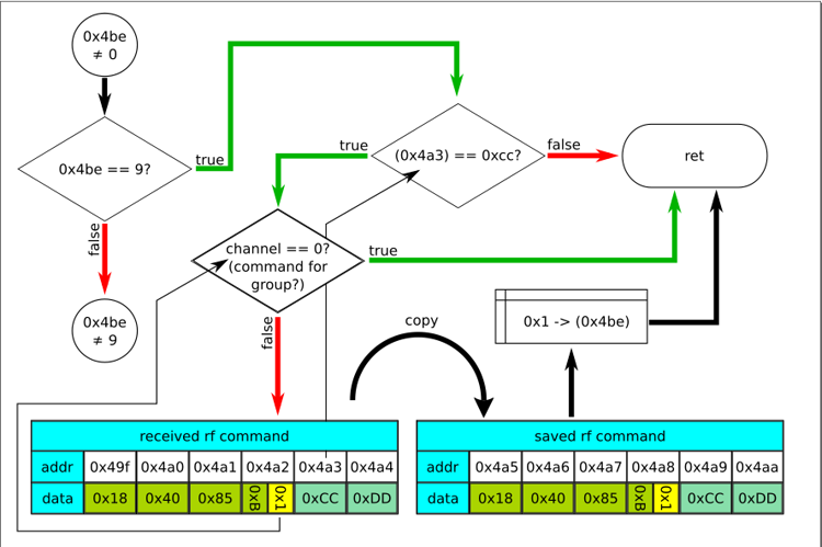

Well, we will consider that the next test we successfully passed. Now the command code is located at 0x4bf. We need to find how the contents of this byte are processed. There are several ways to do this. The simplest is a text search on disassembled code in Ghidra. It remains to see exactly where the contents of this byte are read. This is not a guaranteed way to find all the calls, but in this particular case it will work. So, first, we will see a byte reading in the procedure starting at 0x1262:
The appeal to which comes from a single place - a team located at 0x5e0.
Function graph:
It’s a pity, but all the command codes, except for the already known ones: 0x11, 0x33, 0x55 and 0xcc are discarded in this procedure. Even the codes 0xad and 0xda found in the previous step. At least I was not able to find new codes for the radio commands in the firmware of the AM82TV electric cornice.
Nevertheless, there is access to the firmware, it can be disassembled, see how specific functions are implemented and change something for yourself. Or even add something.
The firmware and the avr8.pspec file modified for atmega168 are posted on GitHub .
All Articles