Training Cisco 200-125 CCNA v3.0. Day 16. Networking in a small office
Today I will tell you how to organize a network in a small office of the company. We have reached a certain stage of training devoted to switches - today we will have the last video that completes the topic of Cisco switches. Of course, we will return to switches, and in the next video tutorial I will show you a road map so that everyone understands in which direction we are moving and what part of the course we have already mastered.
Day 18 of our classes will be the beginning of a new topic dedicated to routers, and the next lesson, Day 17, I will devote a review lecture on the topics studied and talk about plans for further training. Before we get into the topic of the lesson today, I’ll tell you not to forget to share these videos, subscribe to our YouTube channel, visit the Facebook group and www.nwking.org , where you can read the announcements of the new lesson series.
So, let's get started on creating an office network. If you divide this process into parts, the first thing you need to do is find out the requirements that this network must meet. So before you start creating a network for a small office, home network or any other local network, you need to make a list of requirements for it.
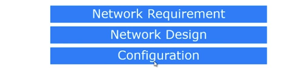
The second thing that needs to be done is to develop a network design, decide how you plan to meet the requirements, and the third is to create a physical network configuration.
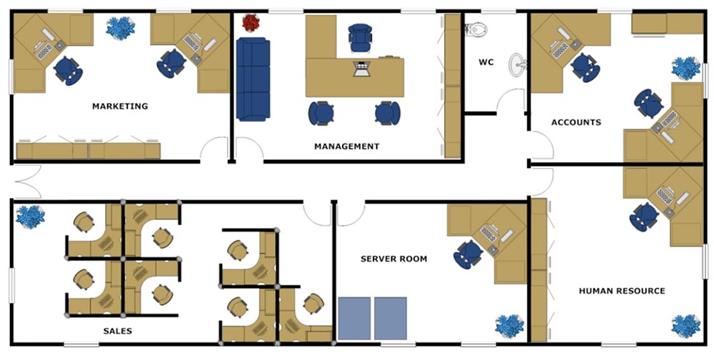
Suppose we are talking about a new office in which there are various departments: the marketing department Marketing, the administrative department Management, the financial department Accounts, the human resources department of the human resource and the server room Server room, where you will be as an IT support specialist and system administrator . Next is the Sales Department premises.
The requirements for the designed network are that employees of different departments should not be connected with each other. This means that, for example, employees in the sales department, which has 7 computers, can only exchange files and messages over the network with each other. Similarly, two computers in the marketing department can only communicate with each other. The administrative department, which has 1 computer, may expand in the future to several employees. Likewise, accounting and human resources should have a separate network of their own.
This is the requirement for our network. As I said, the server room is the room where you will sit and from where you will support the entire office network. Since this is a new network, you are free to choose its configuration, how to plan it. Before continuing, I want to show what the server room looks like.
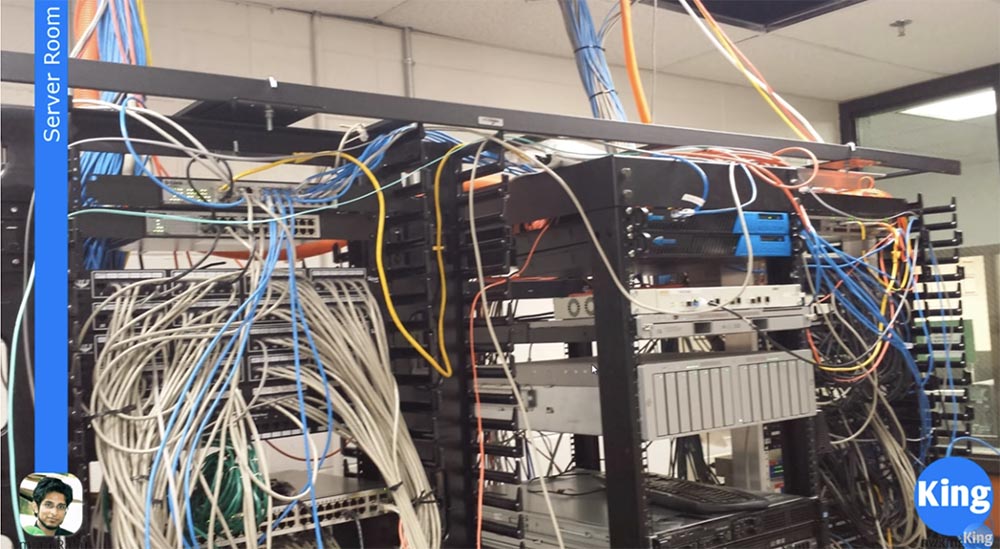
It depends on you, as a network administrator, whether your server room will look like the one shown on the first slide, or the way it is shown on the second.
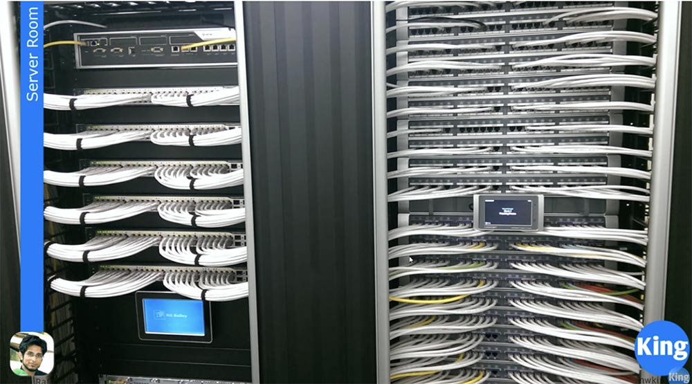
The difference between the two server rooms depends on how disciplined you are. If you follow the practice of labeling network cables with tags and labels, you can maintain the office network in order. As you can see, in the second server, all cables are put in order and each group of cables is equipped with a tag with a designation where these cables go. For example, one cable goes to the sales department, the other to the administration and so on, that is, everything is identified.
You can make a server room, as shown in the first slide, if you have only 10 computers. You can poke cables in random order and arrange the switches somehow without any system in their location. This is not a problem as long as you have a small network. But as the number of computers increases and the company network expands, the moment will come when you will spend most of the time identifying all these cables. You can accidentally cut off the cable that goes to some computer or just don’t understand which cable is connected to which port.
So smart organization of the location of your server devices is in your interests. The next important thing to talk about is network development - cables, plugs and cable outlets. We talked a lot about switches, but forgot to talk about cables.
A CAT5 or CAT6 cable is commonly called unshielded twisted pair cable or UTP cable. If you remove the protective sheath of such a cable, you will see 8 pairs of twisted wires: green and white-green, orange and white-orange, brown and white-brown, blue and white-blue. Why are they twisted? When electromagnetic interference of electrical signals occurs in two parallel wires, noise is created that causes the signal to weaken with an increase in wire length. Twisting the wires mutually compensates for the induced currents, reduces interference and increases the signal transmission distance.

We have 6 categories of network cable - from 1 to 6. As the category increases, the signal transmission distance increases, to a greater extent because the degree of twisting of the pairs increases. A CAT6 cable has many more turns per unit length than CAT5, so it is much more expensive. Accordingly, category 6 cable provides greater data transmission speed over a greater distance. The most common cable categories on the market are cables 5, 5e and 6. Cable 5e is an improved category 5, most companies use it, but CAT6 is mainly used to create modern office networks.
If you strip this cable from the sheath, it will have 4 twisted pairs, as shown in the slide. You also have an RJ-45 connector that contains 8 metal contacts. You must insert the cable wires into the connector and use a crimping tool called a crimper. In order to compress the twisted pair wires, you need to know how to properly position them in the connector. For this, the following schemes are used.
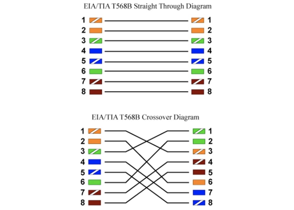
There is a straight and cross, or crossover crimp twisted pair. In the first case, you connect the wires of the same color to each other, that is, you connect the white-orange wire with 1 pin of the RJ-45 connector, orange - with the second, white-green - with the third and further, as shown in the diagram.
Usually, if you connect 2 different devices, for example, a switch and a hub or a switch and a router, you use direct crimping. If you want to connect the same devices, for example, a switch with another switch, you must use a crossover. In both cases, a wire of the same color connects to a wire of the same color, you just change the relative position of the wires and contacts of the connector.
To understand this, think about the phone. You speak into the microphone of the phone, and listen to the sound from the speaker. If you are talking with your friend, what you say into the microphone goes to the speaker of his phone, and what your friend says into your microphone, you hear from your speaker.
This is what a crossover type connection is. If your microphones are connected to each other and also connected speakers, the phones will not work. This is not the most suitable analogy, but I hope you understand the essence of the crossover: the receiver wire goes to the transmitter wire, and the transmitter wire goes to the receiver.
The direct connection scheme of various devices works as follows: the switch and the router have different ports, and if the contacts 1 and 2 of the switch are intended for transmission, then the contacts 1 and 2 of the router are intended for reception. If the devices are the same, then pins 1 and 2 of both the first and second switches are used for transmission, and since the wires for transmission cannot be connected to the same wires, the pins 1 and 2 of the transmitter of the first switch are connected to pins 3 and 6 of the second switch, that is, with the receiver. That's what the crossover is for.
But today these schemes are outdated, Auto-MDIX is used instead - an environment-specific data transfer interface. You can learn about it from Google or a Wikipedia article, I don’t want to waste time on it. In short, this electrical and mechanical interface allows you to use any cable, for example, a direct connection, and a smart device will itself determine which type of cable is used - a transmitter or a receiver, and connect it accordingly.
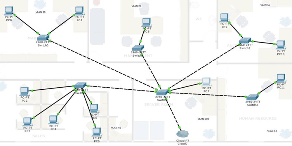
So, we looked at how to connect the cables and now let's move on to the requirements of network design. Let's open the Cisco Packet Tracer and see that I placed the diagram of our office as a substrate for the top layer of network development. Since there are different networks in different departments, it is best to organize them from independent switches. I will place one switch in each room, so we only have six switches from SW0 to SW5. Then I will place 1 computer for each office worker - only 12 pieces from PC0 to PC11. After that, I will connect each computer to the switch using a cable. Such a scheme is quite safe, data from one department is not available for another department, you do not know about the successes or failures of another department, and this is the correct office policy. Perhaps someone in the sales department has the ability of a hacker and could penetrate the computers of the marketing department through a common network and delete information, or employees of different departments simply should not exchange data for business reasons, and so on, so that separate networks help prevent similar cases.
The problem is as follows. I will add a cloud below the pictures - this is the Internet, to which the network administrator’s computer is connected to the server through the switch.
You cannot provide each department with individual access to the Internet, therefore you must connect the switches of the departments with the switch in the server room. This is exactly what the requirement for connecting the office Internet sounds - all individual devices must be connected to a common switch that has access outside the office network.
Here we have a well-known problem: if you leave the network with the default settings, then all computers will be able to communicate with each other, because they will be connected to the same native VLAN1. To avoid this, we need to create different VLANs.
We will work with the network 192.168.1.0/24, which we will divide into several small subnets. We start by creating a VLAN10 voice network with an address space of 192.168.1.0/26. You can look at the table in one of the previous video tutorials and tell me how many hosts will be in this network - / 26 means 2 borrowed bits that divide the network into 4 parts with 64 addresses, so there will be 62 free IP addresses for your subnet hosts. We must create a separate voice network to separate voice from data. This must be done so that the attacker could not connect to the phone conversation and use Wireshark to decrypt the data transmitted on the same channel as voice communication.
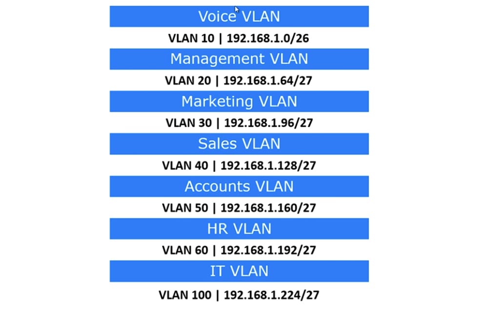
Therefore, VLAN10 will only be used for IP telephony. Slash 26 means that 62 phones can be connected to this network. Next, we will create a network for the administrative department of VLAN20 with an address space of 192.168.1.64/27, that is, the range of network addresses will be 32 with 30 valid host IP addresses. VLAN30 will be transferred to the marketing department, VLAN40 to the sales department, VLAN50 to the finance department, VLAN60 to the human resources department, and VLAN100 will be the IT department network.
Let's mark these networks in the office network topology diagram and start with VLAN20, because VLAN10 is reserved for telephony. After that, we can assume that we have developed the design of a new office network.
If you remember, I said that your server room may have a chaotic layout or be carefully planned. In any case, you need to have documentation - it can be records on paper or in a computer in which the structure of your network will be fixed, all subnets, connections, IP addresses and other information necessary for the work of the network administrator will be described. In this case, as the network develops, you will always own the situation. This will help you save time and trouble when connecting new devices and creating new subnets.
So, after we created separate subnets for each department, that is, made it so that devices can only communicate within their VLANs, this begs the question. As you remember, a switch in the server room is the central communicator to which all other switches are closed, so it should know about all the networks in the office. However, switch SW0 should only know about VLAN30, because there are no other networks in this section. Now imagine that we have expanded the sales department and we will have to transfer part of the employees to the premises of the marketing department. In this case, we will need to create a VLAN40 network in the marketing department, which will also need to be connected to the SW0 switch.
In one of the previous videos, we discussed what is called interface management, that is, we went into VLAN1 and assigned an IP address. Now we need to configure 2 computers of the management department so that they are connected to the access ports of the switch that correspond to VLAN30.
Let's look at your PC7 computer, from which you, as a network administrator, must remotely manage all the network switches. One way to ensure this is to go to the management department and manually configure the SW0 switch so that it is connected to your computer. However, you must be able to remotely configure this switch, because on-site configuration is not always possible. But you are on a VLAN100 network because PC7 is connected to the VLAN100 switch port.
The SW0 switch knows nothing about the VLAN100 network, so we must assign the VLAN100 to one of its ports so that PC7 can communicate with it. If you assign the IP address of VLAN30 to SW0, only PC0 and PC1 can connect to it. However, you must be able to manage this switch from your PC7 VLAN100-related computer. Therefore, we need to create the interface for VLAN100 in switch SW0. We must do the same with the rest of the switches - all these devices must have a VLAN100 interface, to which we must assign an IP address from the range of addresses used by PC7. This address is taken from the range 192.168.1.224/27 of the IT VLAN and is assigned to all switch ports to which VLAN100 is assigned.
After that, you from the server, from your computer, will be able to contact any of the switches using the Telnet protocol and configure them in accordance with the requirements of the network. However, as a network administrator, you also need access to these switches via an external communication channel, or out of band access. To provide this access, you need a device called a Terminal Server, or a terminal server.
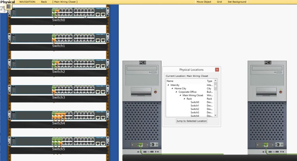
According to the logical topology of the network, all these switches are located in different rooms, but physically they can be installed on a common rack in the server room. In the same rack, you can insert a terminal server to which all computers will be connected. Optical cables come out of this server, on one end of which there is a Serial connector, and on the other - a regular plug for CAT5 cable. All these cables are connected to the console ports of the switches installed in the rack. Each optical cable can connect 8 devices. This terminal server must be connected to your PC7 computer. Thus, through Terminal Server you can connect to the console port of any of the switches via an external communication channel.
You may ask why this is necessary if all these devices are located next to you in the same server room. The fact is that your computer can directly connect to only one console port. Therefore, to test several switches, you will need to physically disconnect the cable from one device in order to connect to another. When using a terminal server, just press one key on the keyboard of your computer to connect to the console port of switch # 0, to switch to another switch just press another key, and so on. Thus, you can manage any of the switches by simply pressing keys. Therefore, under normal circumstances, you need a terminal server to manage switches when troubleshooting network problems.
So, we are done with the development of the network design and now consider the basic network settings.

Each of the devices needs to be assigned a host name, which you must do using the command line. I hope that at the same time you learn this course, you will gain practical knowledge, so you know by heart the commands necessary to assign a host name, create a welcome banner, set a password for the console, password for Telnet and enable password request mode. You need to know how to manage the IP address of the switch, assign a default gateway, administratively disconnect the device, enter denial commands, and save the changes to the switch settings.
If you follow all three steps: determine the requirements for the network, draw a diagram of the future network at least on paper and then go to the settings, you can easily organize your server room.
As I said, we’ve almost finished studying the switches, although we’ll still come back to them, so in the next video tutorials we’ll move on to routers. This is a very interesting topic, which I will try to cover as fully as possible. We will look at the first video about routers through a lesson, and the next lesson, Day 17, I will devote to the results of the CCNA course work, tell you what part of the course you have already mastered and how much you still have to study so that everyone clearly understands what stage of training he has reached.
Soon I plan to post practical tasks on our website, and if you sign up, you will be able to perform tests similar to those that you will have to complete when passing the CCNA certification exam.
Thank you for staying with us. Do you like our articles? Want to see more interesting materials? Support us by placing an order or recommending it to your friends, a 30% discount for Habr users on a unique analogue of entry-level servers that we invented for you: The whole truth about VPS (KVM) E5-2650 v4 (6 Cores) 10GB DDR4 240GB SSD 1Gbps from $ 20 or how to divide the server? (options are available with RAID1 and RAID10, up to 24 cores and up to 40GB DDR4).
Dell R730xd 2 times cheaper? Only we have 2 x Intel TetraDeca-Core Xeon 2x E5-2697v3 2.6GHz 14C 64GB DDR4 4x960GB SSD 1Gbps 100 TV from $ 199 in the Netherlands! Dell R420 - 2x E5-2430 2.2Ghz 6C 128GB DDR3 2x960GB SSD 1Gbps 100TB - from $ 99! Read about How to Build Infrastructure Bldg. class c using Dell R730xd E5-2650 v4 servers costing 9,000 euros for a penny?
Day 18 of our classes will be the beginning of a new topic dedicated to routers, and the next lesson, Day 17, I will devote a review lecture on the topics studied and talk about plans for further training. Before we get into the topic of the lesson today, I’ll tell you not to forget to share these videos, subscribe to our YouTube channel, visit the Facebook group and www.nwking.org , where you can read the announcements of the new lesson series.
So, let's get started on creating an office network. If you divide this process into parts, the first thing you need to do is find out the requirements that this network must meet. So before you start creating a network for a small office, home network or any other local network, you need to make a list of requirements for it.
The second thing that needs to be done is to develop a network design, decide how you plan to meet the requirements, and the third is to create a physical network configuration.
Suppose we are talking about a new office in which there are various departments: the marketing department Marketing, the administrative department Management, the financial department Accounts, the human resources department of the human resource and the server room Server room, where you will be as an IT support specialist and system administrator . Next is the Sales Department premises.
The requirements for the designed network are that employees of different departments should not be connected with each other. This means that, for example, employees in the sales department, which has 7 computers, can only exchange files and messages over the network with each other. Similarly, two computers in the marketing department can only communicate with each other. The administrative department, which has 1 computer, may expand in the future to several employees. Likewise, accounting and human resources should have a separate network of their own.
This is the requirement for our network. As I said, the server room is the room where you will sit and from where you will support the entire office network. Since this is a new network, you are free to choose its configuration, how to plan it. Before continuing, I want to show what the server room looks like.
It depends on you, as a network administrator, whether your server room will look like the one shown on the first slide, or the way it is shown on the second.
The difference between the two server rooms depends on how disciplined you are. If you follow the practice of labeling network cables with tags and labels, you can maintain the office network in order. As you can see, in the second server, all cables are put in order and each group of cables is equipped with a tag with a designation where these cables go. For example, one cable goes to the sales department, the other to the administration and so on, that is, everything is identified.
You can make a server room, as shown in the first slide, if you have only 10 computers. You can poke cables in random order and arrange the switches somehow without any system in their location. This is not a problem as long as you have a small network. But as the number of computers increases and the company network expands, the moment will come when you will spend most of the time identifying all these cables. You can accidentally cut off the cable that goes to some computer or just don’t understand which cable is connected to which port.
So smart organization of the location of your server devices is in your interests. The next important thing to talk about is network development - cables, plugs and cable outlets. We talked a lot about switches, but forgot to talk about cables.
A CAT5 or CAT6 cable is commonly called unshielded twisted pair cable or UTP cable. If you remove the protective sheath of such a cable, you will see 8 pairs of twisted wires: green and white-green, orange and white-orange, brown and white-brown, blue and white-blue. Why are they twisted? When electromagnetic interference of electrical signals occurs in two parallel wires, noise is created that causes the signal to weaken with an increase in wire length. Twisting the wires mutually compensates for the induced currents, reduces interference and increases the signal transmission distance.
We have 6 categories of network cable - from 1 to 6. As the category increases, the signal transmission distance increases, to a greater extent because the degree of twisting of the pairs increases. A CAT6 cable has many more turns per unit length than CAT5, so it is much more expensive. Accordingly, category 6 cable provides greater data transmission speed over a greater distance. The most common cable categories on the market are cables 5, 5e and 6. Cable 5e is an improved category 5, most companies use it, but CAT6 is mainly used to create modern office networks.
If you strip this cable from the sheath, it will have 4 twisted pairs, as shown in the slide. You also have an RJ-45 connector that contains 8 metal contacts. You must insert the cable wires into the connector and use a crimping tool called a crimper. In order to compress the twisted pair wires, you need to know how to properly position them in the connector. For this, the following schemes are used.
There is a straight and cross, or crossover crimp twisted pair. In the first case, you connect the wires of the same color to each other, that is, you connect the white-orange wire with 1 pin of the RJ-45 connector, orange - with the second, white-green - with the third and further, as shown in the diagram.
Usually, if you connect 2 different devices, for example, a switch and a hub or a switch and a router, you use direct crimping. If you want to connect the same devices, for example, a switch with another switch, you must use a crossover. In both cases, a wire of the same color connects to a wire of the same color, you just change the relative position of the wires and contacts of the connector.
To understand this, think about the phone. You speak into the microphone of the phone, and listen to the sound from the speaker. If you are talking with your friend, what you say into the microphone goes to the speaker of his phone, and what your friend says into your microphone, you hear from your speaker.
This is what a crossover type connection is. If your microphones are connected to each other and also connected speakers, the phones will not work. This is not the most suitable analogy, but I hope you understand the essence of the crossover: the receiver wire goes to the transmitter wire, and the transmitter wire goes to the receiver.
The direct connection scheme of various devices works as follows: the switch and the router have different ports, and if the contacts 1 and 2 of the switch are intended for transmission, then the contacts 1 and 2 of the router are intended for reception. If the devices are the same, then pins 1 and 2 of both the first and second switches are used for transmission, and since the wires for transmission cannot be connected to the same wires, the pins 1 and 2 of the transmitter of the first switch are connected to pins 3 and 6 of the second switch, that is, with the receiver. That's what the crossover is for.
But today these schemes are outdated, Auto-MDIX is used instead - an environment-specific data transfer interface. You can learn about it from Google or a Wikipedia article, I don’t want to waste time on it. In short, this electrical and mechanical interface allows you to use any cable, for example, a direct connection, and a smart device will itself determine which type of cable is used - a transmitter or a receiver, and connect it accordingly.
So, we looked at how to connect the cables and now let's move on to the requirements of network design. Let's open the Cisco Packet Tracer and see that I placed the diagram of our office as a substrate for the top layer of network development. Since there are different networks in different departments, it is best to organize them from independent switches. I will place one switch in each room, so we only have six switches from SW0 to SW5. Then I will place 1 computer for each office worker - only 12 pieces from PC0 to PC11. After that, I will connect each computer to the switch using a cable. Such a scheme is quite safe, data from one department is not available for another department, you do not know about the successes or failures of another department, and this is the correct office policy. Perhaps someone in the sales department has the ability of a hacker and could penetrate the computers of the marketing department through a common network and delete information, or employees of different departments simply should not exchange data for business reasons, and so on, so that separate networks help prevent similar cases.
The problem is as follows. I will add a cloud below the pictures - this is the Internet, to which the network administrator’s computer is connected to the server through the switch.
You cannot provide each department with individual access to the Internet, therefore you must connect the switches of the departments with the switch in the server room. This is exactly what the requirement for connecting the office Internet sounds - all individual devices must be connected to a common switch that has access outside the office network.
Here we have a well-known problem: if you leave the network with the default settings, then all computers will be able to communicate with each other, because they will be connected to the same native VLAN1. To avoid this, we need to create different VLANs.
We will work with the network 192.168.1.0/24, which we will divide into several small subnets. We start by creating a VLAN10 voice network with an address space of 192.168.1.0/26. You can look at the table in one of the previous video tutorials and tell me how many hosts will be in this network - / 26 means 2 borrowed bits that divide the network into 4 parts with 64 addresses, so there will be 62 free IP addresses for your subnet hosts. We must create a separate voice network to separate voice from data. This must be done so that the attacker could not connect to the phone conversation and use Wireshark to decrypt the data transmitted on the same channel as voice communication.
Therefore, VLAN10 will only be used for IP telephony. Slash 26 means that 62 phones can be connected to this network. Next, we will create a network for the administrative department of VLAN20 with an address space of 192.168.1.64/27, that is, the range of network addresses will be 32 with 30 valid host IP addresses. VLAN30 will be transferred to the marketing department, VLAN40 to the sales department, VLAN50 to the finance department, VLAN60 to the human resources department, and VLAN100 will be the IT department network.
Let's mark these networks in the office network topology diagram and start with VLAN20, because VLAN10 is reserved for telephony. After that, we can assume that we have developed the design of a new office network.
If you remember, I said that your server room may have a chaotic layout or be carefully planned. In any case, you need to have documentation - it can be records on paper or in a computer in which the structure of your network will be fixed, all subnets, connections, IP addresses and other information necessary for the work of the network administrator will be described. In this case, as the network develops, you will always own the situation. This will help you save time and trouble when connecting new devices and creating new subnets.
So, after we created separate subnets for each department, that is, made it so that devices can only communicate within their VLANs, this begs the question. As you remember, a switch in the server room is the central communicator to which all other switches are closed, so it should know about all the networks in the office. However, switch SW0 should only know about VLAN30, because there are no other networks in this section. Now imagine that we have expanded the sales department and we will have to transfer part of the employees to the premises of the marketing department. In this case, we will need to create a VLAN40 network in the marketing department, which will also need to be connected to the SW0 switch.
In one of the previous videos, we discussed what is called interface management, that is, we went into VLAN1 and assigned an IP address. Now we need to configure 2 computers of the management department so that they are connected to the access ports of the switch that correspond to VLAN30.
Let's look at your PC7 computer, from which you, as a network administrator, must remotely manage all the network switches. One way to ensure this is to go to the management department and manually configure the SW0 switch so that it is connected to your computer. However, you must be able to remotely configure this switch, because on-site configuration is not always possible. But you are on a VLAN100 network because PC7 is connected to the VLAN100 switch port.
The SW0 switch knows nothing about the VLAN100 network, so we must assign the VLAN100 to one of its ports so that PC7 can communicate with it. If you assign the IP address of VLAN30 to SW0, only PC0 and PC1 can connect to it. However, you must be able to manage this switch from your PC7 VLAN100-related computer. Therefore, we need to create the interface for VLAN100 in switch SW0. We must do the same with the rest of the switches - all these devices must have a VLAN100 interface, to which we must assign an IP address from the range of addresses used by PC7. This address is taken from the range 192.168.1.224/27 of the IT VLAN and is assigned to all switch ports to which VLAN100 is assigned.
After that, you from the server, from your computer, will be able to contact any of the switches using the Telnet protocol and configure them in accordance with the requirements of the network. However, as a network administrator, you also need access to these switches via an external communication channel, or out of band access. To provide this access, you need a device called a Terminal Server, or a terminal server.
According to the logical topology of the network, all these switches are located in different rooms, but physically they can be installed on a common rack in the server room. In the same rack, you can insert a terminal server to which all computers will be connected. Optical cables come out of this server, on one end of which there is a Serial connector, and on the other - a regular plug for CAT5 cable. All these cables are connected to the console ports of the switches installed in the rack. Each optical cable can connect 8 devices. This terminal server must be connected to your PC7 computer. Thus, through Terminal Server you can connect to the console port of any of the switches via an external communication channel.
You may ask why this is necessary if all these devices are located next to you in the same server room. The fact is that your computer can directly connect to only one console port. Therefore, to test several switches, you will need to physically disconnect the cable from one device in order to connect to another. When using a terminal server, just press one key on the keyboard of your computer to connect to the console port of switch # 0, to switch to another switch just press another key, and so on. Thus, you can manage any of the switches by simply pressing keys. Therefore, under normal circumstances, you need a terminal server to manage switches when troubleshooting network problems.
So, we are done with the development of the network design and now consider the basic network settings.
Each of the devices needs to be assigned a host name, which you must do using the command line. I hope that at the same time you learn this course, you will gain practical knowledge, so you know by heart the commands necessary to assign a host name, create a welcome banner, set a password for the console, password for Telnet and enable password request mode. You need to know how to manage the IP address of the switch, assign a default gateway, administratively disconnect the device, enter denial commands, and save the changes to the switch settings.
If you follow all three steps: determine the requirements for the network, draw a diagram of the future network at least on paper and then go to the settings, you can easily organize your server room.
As I said, we’ve almost finished studying the switches, although we’ll still come back to them, so in the next video tutorials we’ll move on to routers. This is a very interesting topic, which I will try to cover as fully as possible. We will look at the first video about routers through a lesson, and the next lesson, Day 17, I will devote to the results of the CCNA course work, tell you what part of the course you have already mastered and how much you still have to study so that everyone clearly understands what stage of training he has reached.
Soon I plan to post practical tasks on our website, and if you sign up, you will be able to perform tests similar to those that you will have to complete when passing the CCNA certification exam.
Thank you for staying with us. Do you like our articles? Want to see more interesting materials? Support us by placing an order or recommending it to your friends, a 30% discount for Habr users on a unique analogue of entry-level servers that we invented for you: The whole truth about VPS (KVM) E5-2650 v4 (6 Cores) 10GB DDR4 240GB SSD 1Gbps from $ 20 or how to divide the server? (options are available with RAID1 and RAID10, up to 24 cores and up to 40GB DDR4).
Dell R730xd 2 times cheaper? Only we have 2 x Intel TetraDeca-Core Xeon 2x E5-2697v3 2.6GHz 14C 64GB DDR4 4x960GB SSD 1Gbps 100 TV from $ 199 in the Netherlands! Dell R420 - 2x E5-2430 2.2Ghz 6C 128GB DDR3 2x960GB SSD 1Gbps 100TB - from $ 99! Read about How to Build Infrastructure Bldg. class c using Dell R730xd E5-2650 v4 servers costing 9,000 euros for a penny?
All Articles