Apollo Guidance Computer - architecture and system software. Part 2
Link to Part 1
In this part, we will look at how the AGC is organized from the perspective of a programmer. The list of references and sources is given at the end of the first part of the article. The material of this part is based on the material of the book [1].

AGC uses 15-bit words, with a sign in the 15th place. There is also a parity discharge, which is recorded and controlled by hardware and is completely transparent to the software, with each read and write operation to memory.

Integers are presented in the format of "addition 1". It is as follows:
Non-negative numbers from 0 to 16383 are presented in the form of codes from 000 000 000 000 000 to 011 111 111 111 111, respectively.
Negative numbers are formed by inverting positive numbers, i.e. -1 is represented as 111 111 111 111 111, and up to -16383, represented by binary code 100,000,000,000,000.
Arithmetic operations are performed as follows:
Adding two negative numbers is somewhat more complicated.
If we add according to the usual rules, then nothing will work out:
However, you may notice that the addition of the most significant bits generates a carry bit. We just need to add the carry bit to get the correct result:
You can also notice that in this system positive and negative zero are possible, which creates additional difficulties for programmers, for example, when comparing the result of an operation with zero.
Battery overflow during arithmetic operations can also be monitored, which will be discussed below.
ACG only supports integer arithmetic and cannot perform operations with real numbers in hardware, but can do this in software. The AGC uses a binary decimal representation of 28-bit numbers (9 decimal places), which occupies two memory locations, 14 bits each. Sign digits are also used, and the low word and high word can have a different sign! That is, there may be a number represented as, for example, +5 * 10000 + -5 * 100 = 49500. Strange, but possible.
Distances and speeds for calculations are presented in the metric system, but the data for the crew are displayed in the English system of measures (feet, etc.).

Instruction format
In the previous part, it was already mentioned that the computer memory is divided into 2 Kslov RAM and 36 K words ROM. Since the instruction takes only 12 bits for the address value, the principle of dividing memory into banks is used. A special register is used to indicate the current bank.
To transfer to a new memory bank, the “Transfer into New Bank” (TNB) command is used, which performs the following:
AGC has registers mapped to the address space. They occupy the first 48 words of physical memory.
Battery takes address 0 8 .
The battery is used in most arithmetic and logical operations (OR, AND, etc.). Although the AGC operates with 15-bit words, the battery has a capacity of 16 bits, since it stores an overflow discharge. When data is loaded into the battery, it falls into the lower bits, with bit 14 containing the sign of the number. After performing the arithmetic operation, if overflow has not occurred, then bit 15 will simply contain a copy of the sign, and this bit is invisible to the programmer. We call these sign digits as S1 and S2, respectively. If an overflow has occurred, then S1 and S2 will not be equal. Although the S2 bit remains invisible to the programmer, in AGC there are as many as two ways to set the overflow state.
Firstly, when an overflow occurs, interrupts are automatically disabled. An interrupt handler, if it occurs at this moment, could reset this bit, which would be very undesirable. Interrupts are allowed only when the overflow flag is cleared. The flag is reset only when the battery is cleaned or when a new value is loaded. To check the overflow flag, the Transfer to Storage (TS) command can be used, which saves the battery value to memory only if there was no overflow, and if there was an overflow up or down, the value in the battery is replaced by +1 or -1 respectively. The TS command also skips the next program instruction in case an overflow has occurred. It is assumed that the programmer will write the code that processes the overflow and place it through one command from the TS, and immediately after the TS insert the transition to the instruction after the overflow handler.
Register L - Address 00001 8
The L register is also called the “low order accumulator” and is intended to expand the range of numbers with which operations are performed. It can also be used for temporary storage of variables.
Register Q - Address 00002 8
Register Q is intended to store the return address. The Q register contains a 12-bit address, which, together with the current memory bank, gives the full return address from the subroutine.
EBANK (Erasable Storage Bank) Register - Address 00003 8
RAM (also called “erasable memory” in the AGC) contains 2048 words divided into 8 banks of 256 words each. The RAM bank address has 3 bits and is contained in the EBANK register.
Register FBAN K (Fixed Storage Bank) - Address 00004 8
ROM has banks of 1024 words and contains 36 banks. The FBANK register has 5 bits and allows you to address 32 banks.
Fixed Extension Bit (Superbank Bit)
Used to address the last 4Kslov ROM.
BBANK Register (Both Banks Register) - Address 00006 8
When transferring control to another program, both FBANK and EBANK registers must be changed at the same time. The BBANK register contains both addresses - the numbers of banks of RAM and ROM. Writing to it automatically updates the FBANK and EBANK registers.
Register Z (The program counter) - 00005 8
Register Z is the program counter, that is, it determines the address of the currently executing command. It has a capacity of 12 bits.
Zero Register (A source of zeros) - Address 00007 8
Contains the constant 0.
Interrupt Handler Registers - Address 00008 8 - 00012 8
The registers ZRUPT, BRUPT, ARUPT, LRUPT, QRUPT and BANKRUPT are respectively located at these addresses.
Registers ZRUPT and BRUPT - automatically save the contents of register Z (instruction counter), and register B (internal register, which contains the address of the command that will be executed next).
Registers ARUPT, LRUPT, QRUPT and BANKRUPT are used to save the battery and registers L, Q and BB. These registers must be saved manually and restored manually until the RESUME statement is executed, which serves to return from the interrupt.
During interrupt processing, the AGC disables interrupts until the RESUME statement is executed. Thus, the interrupt handler alone cannot be interrupted.
Earlier it was mentioned that the battery has a capacity of 16 bits, and the most significant bit is used to detect overflow and is not available programmatically. However, the ARUPT register, in which the battery is stored during interruption, has 15 bits. Each time an overflow condition occurs, interrupts are disabled until the overflow flag is cleared.
The ARUPT, LRUPT, QRUPT, and BANKRUPT registers cannot be used outside the interrupt handler. Physically, they remain accessible, but from the point of view of the main program, their state changes at arbitrary points in time.
Editing registers - addresses 00020 8 - 00023 8
The first three registers are shift registers: Cycle Right, Shift Right, Cycle Left, that is, a cyclic shift to the right, a shift to the right, and a cyclic shift to the left. The AGC instruction system does not have shift operations, and in order to shift a number by one bit, it must be written to one of these registers and then counted. Each recording produces a shift of one bit.
The EDOP Register (EDit Interpretive OPcode) is the fourth of the edit registers.
The interpreter commands, which will be discussed below, are stored in two in one word and occupy 7 bits each. An AND operation with a mask is enough to read the low-order command, but the high-order will require a shift of 7 bits. The EDOP register performs this shift in one operation.
Editing registers cannot be used in interrupt handlers, and here's why. Regular registers should be saved at the beginning of the handler, and restored when exiting it. But edit registers perform operations on data when writing to them, and this will lead to incorrect functioning of the interrupted program.
AGC does not use calendar time, days, months, and year. Instead, the countdown is from the “zero” point, which begins a few hours before the start. The clock is displayed in two words in memory, at the addresses 00024 8 (T2), 00025 8 (T1). The word T1 is incremented every 10 ms, the word T2 is approximately every 164 seconds, when the word T1 is full.
00026 8 (T3) Wait list - increment every 10 ms., Shifted relative to T4RUPT by 5 ms
00027 8 (T4) T4RUPT - increment every 10 ms.
00030 8 (T5) Autopilot - increment every 100 ms.
00031 8 (T6) high-resolution clock - increment every 1/1600 s = 0.625 ms.
The first timer, T3, is needed for the task list to work (Wait list). The wait list is a list of very short tasks, each of which takes a short time, and can be executed directly in the interrupt handler. The list contains up to seven tasks, each of which starts at a certain interval. The task execution time is strictly limited to 4 ms. During this time, the computer manages to complete about 160 instructions.
The T4 timer runs critical periodic tasks ranging from 20 to 120 ms, including data exchange with DSKY, polling switches on the ship's control panels and other tasks.
IMU is a gyroscopically stabilized platform with accelerometers, which serves to determine the position and accelerations of the ship in space.

We will not describe here the principle of operation of the gyroscope, we only note that the position of the axes of the gyroscope is measured by the CDU (Coupling Data Unit) device. This device generates pulses when the gyroscopes rotate, producing 32768 pulses per revolution, which corresponds to a resolution of 39.55 arc seconds per pulse.
CDU also transmits to the AGC the position of the axes of the sextant and the approach radar. Since the sextant is only in the command module, and the radar is only in the lunar module, they use the same AGC port.
The IMU also has three pendulum accelerometers (Pulsed Integrating Pendulous Accelerometers, PIPA). But there is a slight subtlety. Despite the fact that the lunar module and the command module have the same IMU, their ranges of speed measurement are different. The speed range of the IMU of the command module is from 0 to 11000 m / s, and for the lunar module - up to 1700 m / s. The IMU resolution of the command module is 5.85 cm / s, for the lunar module - 1 cm / s.
Data transfer from the CDU to the AGC is as follows: pulses from the sensors can increment and decrement counters. The number in the counter has a sign indicating the direction of movement. Counters are located at specific addresses in memory, and can be read out programmatically. A total of 8 counters are used, six of which display speeds and angles, and two are used to display the angular position of the sextant in the command module or the approach radar in the lunar module.
The CDU worked in both directions, for example, it could not only determine the position of the proximity radar, but could also read the contents of the register from the computer's memory and apply voltage to the radar drive motors until the radar was installed at the required angle.
The lunar module has a handle (Attitude Controller Assembly, ACA) whose position could be read out programmatically. Each axis of this controller sent values to the variables P_RHCCTR, Q_RHCCTR and R_RHCCTR.

ACA controller

ACA Controller Appearance
ACA controller installed only in the lunar module
The INLINK device provides two-way communication with the Earth, and serves to transmit telemetric information and receive data from the flight control center. Astronauts can enter the necessary data for the flight through DSKY, but this process is slow and fraught with errors. Through the INLINK register, data can be entered directly from the Earth into the computer.
During the landing process of the lunar module, the AGC continuously calculates the required thrust values and provides control signals to the engines. During the 12 minutes that the landing lasts, the engine burns about half of the fuel, and the program should take into account the reduction in mass. The engine thrust varies from 92.5%, which amounts to 46,700 N, up to 10% of full thrust. But thrust above 65% causes severe wear on the combustion chamber and nozzle, so the AGC program should minimize the time when the engine is in this mode.
The computer is connected to the landing platform engines through the Descent Engine Control Assembly (DECA). Management takes place via the THRUST register. The crew can manually adjust the thrust value through the Thrust / Translational Hand Controller (TTHC).

Thrust / Translational Hand Controller (TTHC).

Thrust / Translational Hand Controller (TTHC). Appearance.
The controller handle is connected directly to DECA, the computer does not see the manually entered values.
Analog indicators, ALTM (analog displays: altimeter and rate meters), are also used to indicate altitude and the rate of change in height that the AGC controls through the ALTM register. Analog indicators are made in the form of vertical scales (tapemeters).

Height and Vertical Speed Indicators
As already mentioned, AGC has two types of memory, RAM, also called “erasable memory”, and ROM (fixed memory). The memory capacity is 38 Kslov, which does not allow addressing the entire memory directly, since the address length in the command word is 12 bits.
To separate the memory into banks, the bank registers EBANK and FBANK are used, which specify the bank of RAM and ROM, respectively. This expands the 32Kwords address space, and for further expanding the ROM address space, the Fixed Extension Bit is used, which allows access to 36Kwords.
RAM has a volume of 2K words, and is divided into 8 banks of 256 words each.

RAM address decryption
To address a word in a RAM bank, 8 bits are needed. Two more bits are needed to determine the type of bank: non-switchable (unswithed) or switchable (swithed). Bits 9 and 10 in the figure above are responsible for this (note that the bits are numbered from 1). If these bits contain 00, 01 and 10, then the EBANK register is not used, if 11 is used, then the contents of EBANK are combined with the 8-bit address recorded in the command word, as shown in the figure below. If the EBANK register is not used, then the first three banks of memory are called, which are called a bit misleading term “Fixed Erasable”. To access RAM, bits 11 and 12 must be set to 0.
Decryption of RAM address using EBANK register
To access the ROM, a similar approach is used. Bits 11 and 12 of the control word determine which banks are used, if these bits contain 00, then RAM is used, as shown in the previous section, if 10 or 11, then all 12 bits are used as an address in the ROM, the FBANK register is not used, if 01, then the address consisting of the lower 10 bits of the control word and the contents of the FBANK register is used.

Decryption of ROM address

Decryption of ROM address using the FBANK register
An important by-product of the memory separation scheme for banks is the ability to connect banks of ROM and RAM to the same address space, and use RAM without having to switch bank registers. The figure explains how such a scheme works.

The scheme of using RAM and ROM in the same address space
To access memory above 32Kwords, the ROM extension bit, Fixed Extension Bit, is used as the Superbank Bit. The superbank bit is located in bit 7 of input / output channel 7. Channel 7 differs from other channels in that it supports both reading and writing. Of course, the ROM expansion bit must be saved both during interrupt handling and when switching tasks.
Note the order in which the FBANK, Z, and BB registers are located in the lower memory. It would seem, why not combine them in one word? But this was done on purpose to create a control transfer mechanism. When switching to another bank, the new values should be set to FBANK and EBANK, or BBANK. However, this raises a problem. Suppose, for example, the program runs at address 01033 8 in the bank of ROM 07, and you need to go to address 02371 8 in the bank of ROM 13. If you change the register Z, it transfers control to address 02371 8 in the current bank, which we do not need. If we switch the current bank first, a similar situation will arise. It is necessary to switch the Z register and the memory bank at the same time. To do this, use the DXCH instruction, which reads the battery and register L, and exchanges their contents with two consecutive locations in memory. Thus, it is possible to exchange the battery and register L either with a pair of FBANK, Z, or with a pair of Z, BB. These options are encoded by two mnemonics: Double Transfer Control Switching Both Banks (DTCB) and Double Transfer Control Switching Fixed Bank (DTCF). The DTCB command allows you to not only go to another address, but also change the RAM bank, and the DTCF command transfers control, leaving the RAM bank the same. The return from the function is as follows. The initial values of Z and BBANK (or FBANK) are written to the accumulator and register L. The called function must save these values and then do the reverse operation by exchanging the values with the registers of banks and Z.
Most computer architectures have a stack pointer and / or index registers (at least one). But not at AGC. Stack pointer support would require additional hardware. There are no index registers that would allow organizing access to data structures at the address (pointer + offset), but there is an INDEX command that eliminates the need for such a register. Also, although there are no hardware index registers, they are emulated by the Interpreter virtual machine, which will be discussed below.
One of the features of AGC is the use of a multi-threaded real-time operating system. For such a system to work, as a rule, a mechanism for locking shared data (mutexes) is required. But in AGC there is no such mechanism, so software developers should carefully check all cases of shared access to data from various processes in order to exclude the possibility of simultaneous access to such data.
4000 8 Startup
Start address after energizing the AGC
4004 8 T6RUPT
TIME6 reaches 0. The timer is used by the autopilot.
4010 8 T5RUPT
TIME5 reached overflow. The timer is used by the autopilot.
4014 8 T3RUPT
TIME3 reached overflow. Used by the WAITLIST task scheduler.
4020 8 T4RUPT
TIME4 reached overflow. Scanning and update and display DSKY
4024 8 KEYRUPT1
pressing DSKY button. The key code from the main DSKY is available on channel 15
4030 8 KEYRUPT2
Press the second DSKY button. The navigation key code DSKY is available on channel 16 (command module only)
4034 8 UPRUPT
Data in the INLINK register
Used for DSKY
4040 8 DOWNRUPT
The Downlink register contains data. Used for telemetry AGC
4044 8 RADARUPT
Data in the RNRAD register. Proximity Radar
4050 8 RUPT10
LM P64
The operation code, or Order Code, in terms of that time, is encoded with three bits, that is, only eight opcodes are possible, which is clearly not enough for a developed command system. However, the developers found a way out. Some codes are expanded with an additional two-bit field, Q-Code.
The opcode 000 corresponds to a large number of special operations, the opcodes 011, 100 and 111 correspond to one operation each. The remaining opcodes 001, 010, 101 and 110 use Q codes.

Q command format
Also, to expand the number of possible opcodes, other tricks were used. Some instructions cannot work with RAM, and specifying RAM as an address might lead to an undefined result, but such opcodes with operand addresses in RAM were used for completely different operations. For example, the transfer control command TC (transfer control) cannot transfer control to RAM, but if the address points to RAM, then this opcode corresponds to the Enable Interrupts command.
When these opcodes were not enough, the following approach was used. If we make a transition with the TC command to the address 00006 8 , in fact, no transition occurs, instead, the one following the TC command 00006 8the opcode is interpreted as belonging to a completely different set of instructions. Of course, such instructions require more time to execute, because the processor must read and decode the two opcodes, but this problem is mitigated by the careful distribution of instructions between the two sets of instructions. Frequently used commands are included in the main instruction set, and the remaining ones in the extended one.
In total, the AGC contains 41 teams. Teams are divided into 6 groups:
However, we will not describe all the AGC teams here. Those interested can refer to the book [1].
AGC does not have hard drives or tape drives, and all communication with the outside world comes down to setting and reading bits in the input / output ports. AGC peripherals include the inertial platform, engines, radar, DSKY, and control panel switches. High-speed data exchange is not required, and the speed of exchange is not a significant limiting factor.
For input and output are the so-called channels. Writing and reading a channel is similar to writing and reading a RAM cell, but unlike RAM, most channels are unidirectional. There are also counting ports, which are used to read the positions of the axes of the IMU, radar and sextant. Pulses from angle sensors increment and decrement counters, which can then be read by AGC.

AGC Peripherals
I / O instructions refer to the extended instruction set and require the EXTEND command before the opcode. I / O commands have an opcode of 000, followed by a three-bit PCode. Different PCode values are used only for ground tests; by default, PCode is zero. The remaining 9 bits of the control word is the channel number. Thus, AGC can address up to 512 channels, but only 16 are used in practice. Most peripheral devices are connected not with a full 15-bit word, but with a separate bit in a word, that is, logical I / O operations AND, OR are required and Exclusive OR. Such operations can be combined into a single operation with an I / O operation. To do this, the instructions are WOR (Write with OR), WAND (Write with AND), ROR (Read and OR) and RXOR (Read and XOR).
I / O instructions use a battery to read and save data. But there is also a register L (low-order accumulator), which can be mapped to a port, then everything that is read and written to it will automatically go to the port. This allows you to use the usual logical operations AND, OR and XOR to work with the port.
But not all I / O operations require reading or writing only one bit. For example, DSKY sends 5-bit key codes. Pressing the button on DSKY generates a KEYRUPT interrupt, the code is placed in the input channel.
Another example when it is necessary to transfer a large amount of data through the port is the uplink and downlink interfaces, which provide communication with the Earth at a speed of 51 kbps or 1900 bps (manually selected by the crew).

AGC software is based on the Real-time Executive operating system and Interpreter virtual machine. We will consider them in detail in the next part.
In this part, we will look at how the AGC is organized from the perspective of a programmer. The list of references and sources is given at the end of the first part of the article. The material of this part is based on the material of the book [1].
Representation of numbers in memory of AGC
AGC uses 15-bit words, with a sign in the 15th place. There is also a parity discharge, which is recorded and controlled by hardware and is completely transparent to the software, with each read and write operation to memory.
Integers are presented in the format of "addition 1". It is as follows:
Non-negative numbers from 0 to 16383 are presented in the form of codes from 000 000 000 000 000 to 011 111 111 111 111, respectively.
Negative numbers are formed by inverting positive numbers, i.e. -1 is represented as 111 111 111 111 111, and up to -16383, represented by binary code 100,000,000,000,000.
Arithmetic operations are performed as follows:
2: 000 000 000 000 010 -5: 111 111 111 111 010 111 111 111 111 100 (= -3)
Adding two negative numbers is somewhat more complicated.
If we add according to the usual rules, then nothing will work out:
-2: 111 111 111 111 101 -5: 111 111 111 111 010 111 111 111 110 111 (= -8)
However, you may notice that the addition of the most significant bits generates a carry bit. We just need to add the carry bit to get the correct result:
-2: 111 111 111 111 101 -5: 111 111 111 111 010 111 111 111 110 111 (= -8) Carry 1 111 111 111 111 000 (= -7)
You can also notice that in this system positive and negative zero are possible, which creates additional difficulties for programmers, for example, when comparing the result of an operation with zero.
Battery overflow during arithmetic operations can also be monitored, which will be discussed below.
ACG only supports integer arithmetic and cannot perform operations with real numbers in hardware, but can do this in software. The AGC uses a binary decimal representation of 28-bit numbers (9 decimal places), which occupies two memory locations, 14 bits each. Sign digits are also used, and the low word and high word can have a different sign! That is, there may be a number represented as, for example, +5 * 10000 + -5 * 100 = 49500. Strange, but possible.
Distances and speeds for calculations are presented in the metric system, but the data for the crew are displayed in the English system of measures (feet, etc.).
Instruction format
Memory model
In the previous part, it was already mentioned that the computer memory is divided into 2 Kslov RAM and 36 K words ROM. Since the instruction takes only 12 bits for the address value, the principle of dividing memory into banks is used. A special register is used to indicate the current bank.
To transfer to a new memory bank, the “Transfer into New Bank” (TNB) command is used, which performs the following:
- Copies the current bank register ("Bank") to the register "Saved Bank"
- Copies a 12-bit address from the memory following the TNB command to the “Return Address” register
- We load the new bank address into the Bank register, and load the offset indicated by the TNB instruction into the instruction counter.
Registers
AGC has registers mapped to the address space. They occupy the first 48 words of physical memory.
Battery takes address 0 8 .
The battery is used in most arithmetic and logical operations (OR, AND, etc.). Although the AGC operates with 15-bit words, the battery has a capacity of 16 bits, since it stores an overflow discharge. When data is loaded into the battery, it falls into the lower bits, with bit 14 containing the sign of the number. After performing the arithmetic operation, if overflow has not occurred, then bit 15 will simply contain a copy of the sign, and this bit is invisible to the programmer. We call these sign digits as S1 and S2, respectively. If an overflow has occurred, then S1 and S2 will not be equal. Although the S2 bit remains invisible to the programmer, in AGC there are as many as two ways to set the overflow state.
Firstly, when an overflow occurs, interrupts are automatically disabled. An interrupt handler, if it occurs at this moment, could reset this bit, which would be very undesirable. Interrupts are allowed only when the overflow flag is cleared. The flag is reset only when the battery is cleaned or when a new value is loaded. To check the overflow flag, the Transfer to Storage (TS) command can be used, which saves the battery value to memory only if there was no overflow, and if there was an overflow up or down, the value in the battery is replaced by +1 or -1 respectively. The TS command also skips the next program instruction in case an overflow has occurred. It is assumed that the programmer will write the code that processes the overflow and place it through one command from the TS, and immediately after the TS insert the transition to the instruction after the overflow handler.
Register L - Address 00001 8
The L register is also called the “low order accumulator” and is intended to expand the range of numbers with which operations are performed. It can also be used for temporary storage of variables.
Register Q - Address 00002 8
Register Q is intended to store the return address. The Q register contains a 12-bit address, which, together with the current memory bank, gives the full return address from the subroutine.
EBANK (Erasable Storage Bank) Register - Address 00003 8
RAM (also called “erasable memory” in the AGC) contains 2048 words divided into 8 banks of 256 words each. The RAM bank address has 3 bits and is contained in the EBANK register.
Register FBAN K (Fixed Storage Bank) - Address 00004 8
ROM has banks of 1024 words and contains 36 banks. The FBANK register has 5 bits and allows you to address 32 banks.
Fixed Extension Bit (Superbank Bit)
Used to address the last 4Kslov ROM.
BBANK Register (Both Banks Register) - Address 00006 8
When transferring control to another program, both FBANK and EBANK registers must be changed at the same time. The BBANK register contains both addresses - the numbers of banks of RAM and ROM. Writing to it automatically updates the FBANK and EBANK registers.
Register Z (The program counter) - 00005 8
Register Z is the program counter, that is, it determines the address of the currently executing command. It has a capacity of 12 bits.
Zero Register (A source of zeros) - Address 00007 8
Contains the constant 0.
Interrupt Handler Registers - Address 00008 8 - 00012 8
The registers ZRUPT, BRUPT, ARUPT, LRUPT, QRUPT and BANKRUPT are respectively located at these addresses.
Registers ZRUPT and BRUPT - automatically save the contents of register Z (instruction counter), and register B (internal register, which contains the address of the command that will be executed next).
Registers ARUPT, LRUPT, QRUPT and BANKRUPT are used to save the battery and registers L, Q and BB. These registers must be saved manually and restored manually until the RESUME statement is executed, which serves to return from the interrupt.
During interrupt processing, the AGC disables interrupts until the RESUME statement is executed. Thus, the interrupt handler alone cannot be interrupted.
Earlier it was mentioned that the battery has a capacity of 16 bits, and the most significant bit is used to detect overflow and is not available programmatically. However, the ARUPT register, in which the battery is stored during interruption, has 15 bits. Each time an overflow condition occurs, interrupts are disabled until the overflow flag is cleared.
The ARUPT, LRUPT, QRUPT, and BANKRUPT registers cannot be used outside the interrupt handler. Physically, they remain accessible, but from the point of view of the main program, their state changes at arbitrary points in time.
Editing registers - addresses 00020 8 - 00023 8
The first three registers are shift registers: Cycle Right, Shift Right, Cycle Left, that is, a cyclic shift to the right, a shift to the right, and a cyclic shift to the left. The AGC instruction system does not have shift operations, and in order to shift a number by one bit, it must be written to one of these registers and then counted. Each recording produces a shift of one bit.
The EDOP Register (EDit Interpretive OPcode) is the fourth of the edit registers.
The interpreter commands, which will be discussed below, are stored in two in one word and occupy 7 bits each. An AND operation with a mask is enough to read the low-order command, but the high-order will require a shift of 7 bits. The EDOP register performs this shift in one operation.
Editing registers cannot be used in interrupt handlers, and here's why. Regular registers should be saved at the beginning of the handler, and restored when exiting it. But edit registers perform operations on data when writing to them, and this will lead to incorrect functioning of the interrupted program.
Timers and clocks
Real time clock
AGC does not use calendar time, days, months, and year. Instead, the countdown is from the “zero” point, which begins a few hours before the start. The clock is displayed in two words in memory, at the addresses 00024 8 (T2), 00025 8 (T1). The word T1 is incremented every 10 ms, the word T2 is approximately every 164 seconds, when the word T1 is full.
Timers
00026 8 (T3) Wait list - increment every 10 ms., Shifted relative to T4RUPT by 5 ms
00027 8 (T4) T4RUPT - increment every 10 ms.
00030 8 (T5) Autopilot - increment every 100 ms.
00031 8 (T6) high-resolution clock - increment every 1/1600 s = 0.625 ms.
The first timer, T3, is needed for the task list to work (Wait list). The wait list is a list of very short tasks, each of which takes a short time, and can be executed directly in the interrupt handler. The list contains up to seven tasks, each of which starts at a certain interval. The task execution time is strictly limited to 4 ms. During this time, the computer manages to complete about 160 instructions.
The T4 timer runs critical periodic tasks ranging from 20 to 120 ms, including data exchange with DSKY, polling switches on the ship's control panels and other tasks.
Inertial Measurement Unit IMU (The Inertial Measurement Unit)
IMU is a gyroscopically stabilized platform with accelerometers, which serves to determine the position and accelerations of the ship in space.
We will not describe here the principle of operation of the gyroscope, we only note that the position of the axes of the gyroscope is measured by the CDU (Coupling Data Unit) device. This device generates pulses when the gyroscopes rotate, producing 32768 pulses per revolution, which corresponds to a resolution of 39.55 arc seconds per pulse.
CDU also transmits to the AGC the position of the axes of the sextant and the approach radar. Since the sextant is only in the command module, and the radar is only in the lunar module, they use the same AGC port.
The IMU also has three pendulum accelerometers (Pulsed Integrating Pendulous Accelerometers, PIPA). But there is a slight subtlety. Despite the fact that the lunar module and the command module have the same IMU, their ranges of speed measurement are different. The speed range of the IMU of the command module is from 0 to 11000 m / s, and for the lunar module - up to 1700 m / s. The IMU resolution of the command module is 5.85 cm / s, for the lunar module - 1 cm / s.
Counters CDUS (X, Y, Z, OPTIS, OPTT) and PIPAS (X, Y, Z)
Data transfer from the CDU to the AGC is as follows: pulses from the sensors can increment and decrement counters. The number in the counter has a sign indicating the direction of movement. Counters are located at specific addresses in memory, and can be read out programmatically. A total of 8 counters are used, six of which display speeds and angles, and two are used to display the angular position of the sextant in the command module or the approach radar in the lunar module.
Device management through counters
The CDU worked in both directions, for example, it could not only determine the position of the proximity radar, but could also read the contents of the register from the computer's memory and apply voltage to the radar drive motors until the radar was installed at the required angle.
Other computer interfaces
The lunar module has a handle (Attitude Controller Assembly, ACA) whose position could be read out programmatically. Each axis of this controller sent values to the variables P_RHCCTR, Q_RHCCTR and R_RHCCTR.
ACA controller
ACA Controller Appearance
ACA controller installed only in the lunar module
INLINK (Telemetry Transmission Channel)
The INLINK device provides two-way communication with the Earth, and serves to transmit telemetric information and receive data from the flight control center. Astronauts can enter the necessary data for the flight through DSKY, but this process is slow and fraught with errors. Through the INLINK register, data can be entered directly from the Earth into the computer.
Engine management
During the landing process of the lunar module, the AGC continuously calculates the required thrust values and provides control signals to the engines. During the 12 minutes that the landing lasts, the engine burns about half of the fuel, and the program should take into account the reduction in mass. The engine thrust varies from 92.5%, which amounts to 46,700 N, up to 10% of full thrust. But thrust above 65% causes severe wear on the combustion chamber and nozzle, so the AGC program should minimize the time when the engine is in this mode.
The computer is connected to the landing platform engines through the Descent Engine Control Assembly (DECA). Management takes place via the THRUST register. The crew can manually adjust the thrust value through the Thrust / Translational Hand Controller (TTHC).
Thrust / Translational Hand Controller (TTHC).
Thrust / Translational Hand Controller (TTHC). Appearance.
The controller handle is connected directly to DECA, the computer does not see the manually entered values.
Analog devices
Analog indicators, ALTM (analog displays: altimeter and rate meters), are also used to indicate altitude and the rate of change in height that the AGC controls through the ALTM register. Analog indicators are made in the form of vertical scales (tapemeters).
Height and Vertical Speed Indicators
Addressing and memory banks
As already mentioned, AGC has two types of memory, RAM, also called “erasable memory”, and ROM (fixed memory). The memory capacity is 38 Kslov, which does not allow addressing the entire memory directly, since the address length in the command word is 12 bits.
To separate the memory into banks, the bank registers EBANK and FBANK are used, which specify the bank of RAM and ROM, respectively. This expands the 32Kwords address space, and for further expanding the ROM address space, the Fixed Extension Bit is used, which allows access to 36Kwords.
RAM banks
RAM has a volume of 2K words, and is divided into 8 banks of 256 words each.
RAM address decryption
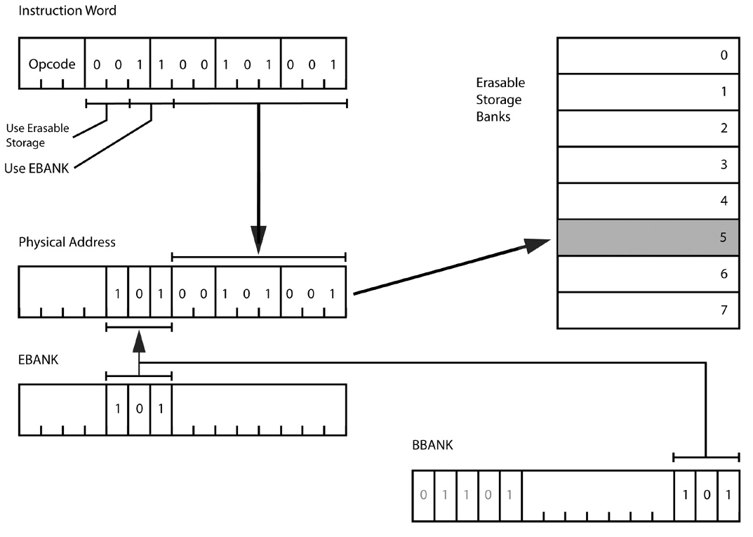
To address a word in a RAM bank, 8 bits are needed. Two more bits are needed to determine the type of bank: non-switchable (unswithed) or switchable (swithed). Bits 9 and 10 in the figure above are responsible for this (note that the bits are numbered from 1). If these bits contain 00, 01 and 10, then the EBANK register is not used, if 11 is used, then the contents of EBANK are combined with the 8-bit address recorded in the command word, as shown in the figure below. If the EBANK register is not used, then the first three banks of memory are called, which are called a bit misleading term “Fixed Erasable”. To access RAM, bits 11 and 12 must be set to 0.
Decryption of RAM address using EBANK register
ROM
To access the ROM, a similar approach is used. Bits 11 and 12 of the control word determine which banks are used, if these bits contain 00, then RAM is used, as shown in the previous section, if 10 or 11, then all 12 bits are used as an address in the ROM, the FBANK register is not used, if 01, then the address consisting of the lower 10 bits of the control word and the contents of the FBANK register is used.
Decryption of ROM address
Decryption of ROM address using the FBANK register
Common banks
An important by-product of the memory separation scheme for banks is the ability to connect banks of ROM and RAM to the same address space, and use RAM without having to switch bank registers. The figure explains how such a scheme works.
The scheme of using RAM and ROM in the same address space
Memory beyond 32 words
To access memory above 32Kwords, the ROM extension bit, Fixed Extension Bit, is used as the Superbank Bit. The superbank bit is located in bit 7 of input / output channel 7. Channel 7 differs from other channels in that it supports both reading and writing. Of course, the ROM expansion bit must be saved both during interrupt handling and when switching tasks.
Transfer of control between banks
Note the order in which the FBANK, Z, and BB registers are located in the lower memory. It would seem, why not combine them in one word? But this was done on purpose to create a control transfer mechanism. When switching to another bank, the new values should be set to FBANK and EBANK, or BBANK. However, this raises a problem. Suppose, for example, the program runs at address 01033 8 in the bank of ROM 07, and you need to go to address 02371 8 in the bank of ROM 13. If you change the register Z, it transfers control to address 02371 8 in the current bank, which we do not need. If we switch the current bank first, a similar situation will arise. It is necessary to switch the Z register and the memory bank at the same time. To do this, use the DXCH instruction, which reads the battery and register L, and exchanges their contents with two consecutive locations in memory. Thus, it is possible to exchange the battery and register L either with a pair of FBANK, Z, or with a pair of Z, BB. These options are encoded by two mnemonics: Double Transfer Control Switching Both Banks (DTCB) and Double Transfer Control Switching Fixed Bank (DTCF). The DTCB command allows you to not only go to another address, but also change the RAM bank, and the DTCF command transfers control, leaving the RAM bank the same. The return from the function is as follows. The initial values of Z and BBANK (or FBANK) are written to the accumulator and register L. The called function must save these values and then do the reverse operation by exchanging the values with the registers of banks and Z.
Some disadvantages of AGC architecture
Most computer architectures have a stack pointer and / or index registers (at least one). But not at AGC. Stack pointer support would require additional hardware. There are no index registers that would allow organizing access to data structures at the address (pointer + offset), but there is an INDEX command that eliminates the need for such a register. Also, although there are no hardware index registers, they are emulated by the Interpreter virtual machine, which will be discussed below.
One of the features of AGC is the use of a multi-threaded real-time operating system. For such a system to work, as a rule, a mechanism for locking shared data (mutexes) is required. But in AGC there is no such mechanism, so software developers should carefully check all cases of shared access to data from various processes in order to exclude the possibility of simultaneous access to such data.
Interruptions
4000 8 Startup
Start address after energizing the AGC
4004 8 T6RUPT
TIME6 reaches 0. The timer is used by the autopilot.
4010 8 T5RUPT
TIME5 reached overflow. The timer is used by the autopilot.
4014 8 T3RUPT
TIME3 reached overflow. Used by the WAITLIST task scheduler.
4020 8 T4RUPT
TIME4 reached overflow. Scanning and update and display DSKY
4024 8 KEYRUPT1
pressing DSKY button. The key code from the main DSKY is available on channel 15
4030 8 KEYRUPT2
Press the second DSKY button. The navigation key code DSKY is available on channel 16 (command module only)
4034 8 UPRUPT
Data in the INLINK register
Used for DSKY
4040 8 DOWNRUPT
The Downlink register contains data. Used for telemetry AGC
4044 8 RADARUPT
Data in the RNRAD register. Proximity Radar
4050 8 RUPT10
LM P64
Command system
The operation code, or Order Code, in terms of that time, is encoded with three bits, that is, only eight opcodes are possible, which is clearly not enough for a developed command system. However, the developers found a way out. Some codes are expanded with an additional two-bit field, Q-Code.
The opcode 000 corresponds to a large number of special operations, the opcodes 011, 100 and 111 correspond to one operation each. The remaining opcodes 001, 010, 101 and 110 use Q codes.
Q command format
Also, to expand the number of possible opcodes, other tricks were used. Some instructions cannot work with RAM, and specifying RAM as an address might lead to an undefined result, but such opcodes with operand addresses in RAM were used for completely different operations. For example, the transfer control command TC (transfer control) cannot transfer control to RAM, but if the address points to RAM, then this opcode corresponds to the Enable Interrupts command.
When these opcodes were not enough, the following approach was used. If we make a transition with the TC command to the address 00006 8 , in fact, no transition occurs, instead, the one following the TC command 00006 8the opcode is interpreted as belonging to a completely different set of instructions. Of course, such instructions require more time to execute, because the processor must read and decode the two opcodes, but this problem is mitigated by the careful distribution of instructions between the two sets of instructions. Frequently used commands are included in the main instruction set, and the remaining ones in the extended one.
Basic Instructions
In total, the AGC contains 41 teams. Teams are divided into 6 groups:
- Arithmetic logic
- Control transfer
- Data movement
- Modification of instructions
- I / O instructions
- miscellanea
However, we will not describe all the AGC teams here. Those interested can refer to the book [1].
Communication with the outside world: input-output subsystem
AGC does not have hard drives or tape drives, and all communication with the outside world comes down to setting and reading bits in the input / output ports. AGC peripherals include the inertial platform, engines, radar, DSKY, and control panel switches. High-speed data exchange is not required, and the speed of exchange is not a significant limiting factor.
For input and output are the so-called channels. Writing and reading a channel is similar to writing and reading a RAM cell, but unlike RAM, most channels are unidirectional. There are also counting ports, which are used to read the positions of the axes of the IMU, radar and sextant. Pulses from angle sensors increment and decrement counters, which can then be read by AGC.
AGC Peripherals
I / O instructions refer to the extended instruction set and require the EXTEND command before the opcode. I / O commands have an opcode of 000, followed by a three-bit PCode. Different PCode values are used only for ground tests; by default, PCode is zero. The remaining 9 bits of the control word is the channel number. Thus, AGC can address up to 512 channels, but only 16 are used in practice. Most peripheral devices are connected not with a full 15-bit word, but with a separate bit in a word, that is, logical I / O operations AND, OR are required and Exclusive OR. Such operations can be combined into a single operation with an I / O operation. To do this, the instructions are WOR (Write with OR), WAND (Write with AND), ROR (Read and OR) and RXOR (Read and XOR).
I / O instructions use a battery to read and save data. But there is also a register L (low-order accumulator), which can be mapped to a port, then everything that is read and written to it will automatically go to the port. This allows you to use the usual logical operations AND, OR and XOR to work with the port.
But not all I / O operations require reading or writing only one bit. For example, DSKY sends 5-bit key codes. Pressing the button on DSKY generates a KEYRUPT interrupt, the code is placed in the input channel.
Another example when it is necessary to transfer a large amount of data through the port is the uplink and downlink interfaces, which provide communication with the Earth at a speed of 51 kbps or 1900 bps (manually selected by the crew).
Software
AGC software is based on the Real-time Executive operating system and Interpreter virtual machine. We will consider them in detail in the next part.
All Articles