Programmer for EPROM on Arduino
When studying and repairing computers that are older than me, it was necessary to flash ROMs. Tests of RAM and peripherals to conduct. I had no normal programmer at that time.
Of course, it is possible to compile on the logic for the LPT port, but this option was discarded, since for use it would have been necessary to include some other old man. In modern computers, this interface is still found (though not a full-fledged connector, but on the comb) and buying a card in a PCI slot is also not a problem, but there are already difficulties with software. It was written a long time ago, when working with input / output ports in operating systems was carried out differently. Accordingly, in modern versions of Windows software will not work.
It’s worth mentioning right away that I know about the existence of TL866. And even during the development process, he bought it for himself, but he is not able to flash chips that require high programming voltage. Maximum 18 volts (TL866 + or 21 for the previous version).
A quick googling led me to this repository . Having assembled the programmer, I was able to dump a couple of chips of interest. But with the firmware everything turned out to be much more complicated ... The software simply does not know how ... Of course, you can fool it by exposing the wrong chip, but this does not work in all cases and it is clearly not our method
I was very disappointed with the user interface, which, instead of the classic version with the right to select the port to the user, went through all available serial interfaces. Accordingly, all devices reboot. It’s especially offensive, probably, when you have a 3D printer for 10 hours printing a part from a USB flash drive, and here such a setup ...
The world of OpenSource is wonderful in that you can take the project and add it to your task. In this case, there are no source codes for the graphical interface. At least I did not find them, although I could write to the developer. It became interesting and there was a small reason to study Qt. So the software will be cross-platform.
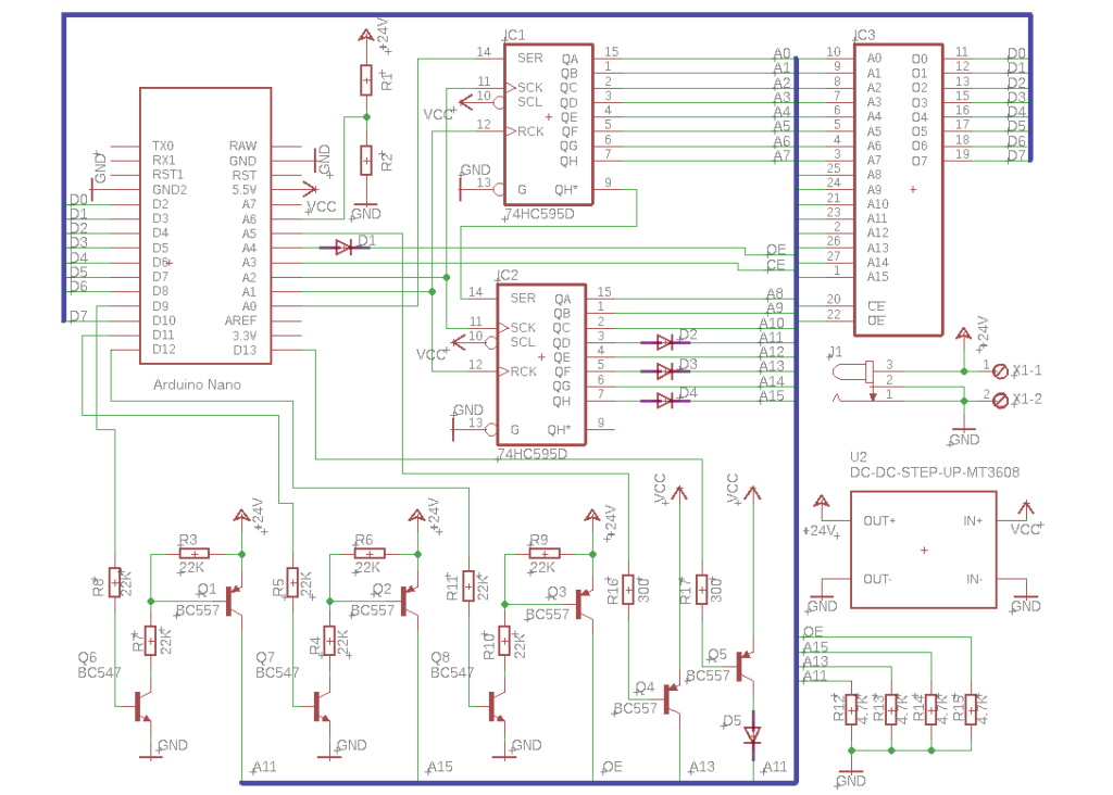
We take as a basis the scheme from the previous project and modify the device to the required functionality. I decided to sacrifice EEPROM support in software. Perhaps this is not a good solution, but electrically erasable chips no longer need such a high voltage. When finalizing, I relied on the most voluminous microcircuit (27C512 for DIP28) and removed all the confusion regarding the address legs. The entire address will be set exclusively using shift registers (74HC595). This will free the extra legs of the microcontroller itself, which will be needed to control the supply of programming voltage. And all the necessary signals (PRG) can be obtained by modifying the address before loading it into the registers.
The principle of applying voltage programming remained the same. Changes only in the field of protection of microcontroller pins and shift registers. I replaced the resistors (1 KOhm) with diodes with a pull-up to the log. 0. This is a less aggressive option. Although, in fairness, and resistors work.
Having studied the documentation for all the chips of interest, I determined that three Vpp feed points are required:
- 27C16 21-foot microcircuit (23 foot DIP28 socket)
- 27C32 and 27C512 per signal #OE (Output Enable)
- 27C64, 27C128, 27C256 on 1 leg of microcircuits
The 27C16 and 27C32 microcircuits differ from the others in the case, so they need to supply power to the 26th leg of the socket. This is the A13 address leg for more capacious brothers. The current from the output of the shift register should be enough to work, but at the time of loading the data, its outputs go into the Z state. A similar mode is acceptable, but switching on to read or write one cell is hardly the norm. Therefore, an additional transistor is installed under the power control. And another one was required for the 27C16, which, for the time of reading, needs to supply 5 volts to the Vpp input. You can, of course, set the programming voltage to 5 volts while reading, but switching between 25 and 5 volts is inconvenient.
If there are ADC free legs, then why not measure the programming voltage? The board is divorced under the Arduino Nano. It has two additional inputs, which, except for the ADC, can not be used. This is actually a feature of many AVR microcontrollers in a surface mount housing. On Chinese Arduino UNO, there are often inputs A6 and A7. Considering that the voltage can be up to 30 volts (it seems that domestic RF5, 25 volts most of all), we calculate the divider from what is available. An accuracy of 0.5 volts is sufficient for this task. This function is foolproof, not a voltmeter.
It was possible, of course, to get confused and act as a WID (pulse width regulation) controller, but there were no free legs. Therefore, on the printed circuit board there is a seat for the DC-DC Step Up converter on the MT3608 chip, which are available for a penny on Ali.
According to the scheme, that’s all.
The algorithm for working with these microcircuits is very simple. You can read it in a short video.
Schemes and software are available in the repository on GitHub: https://github.com/walhi/arduino_eprom27_programmer . During assembly, you can safely change the values of the resistors. True, with the divider, you need to slightly fix the sketch code.
All Articles