GAZ-66 toy on the control panel. Part 1
The last few years I wanted to get a toy on the control panel and always with a video. But do not buy ready-made, but do it yourself. And in the end, I ordered myself such a toy, with a simple control system, but great potential for modernization. It took ~ 9 months to complete all the work from start to near completion. For most of this time, components from China were waiting.
I’m writing an article for the most part for myself, so that I don’t forget what I did in the future, how, why and why.
It will contain two main parts: hardware and software, and possibly another part about the layout of iron. First, I will describe the hardware, from which I collected, what problems I encountered and how I solved them.
1. Hardware
The system consists of a control panel and equipment installed on a typewriter. Let's consider them in more detail.
1.1 Control Panel
Components:
- Raspberry pi 3
- ADS1115 ADC
- Game hat
Game hat
Game HAT was selected because This is a ready-made solution combining a screen, joystick and keyboard sufficient to control the machine.
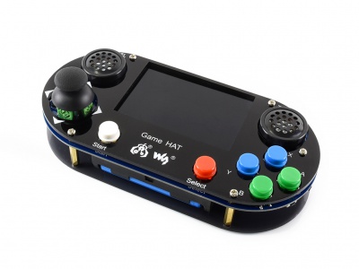
The joystick on this board is KY-023. He decided to use instead of the steering wheel. But it turned out that the Raspberry does not have an ADC and the only values that could be obtained from it are 0 and 1, which is clearly not enough for a smooth rotation of the wheels.

ADS1115
This problem was solved by the ADS1115 module.
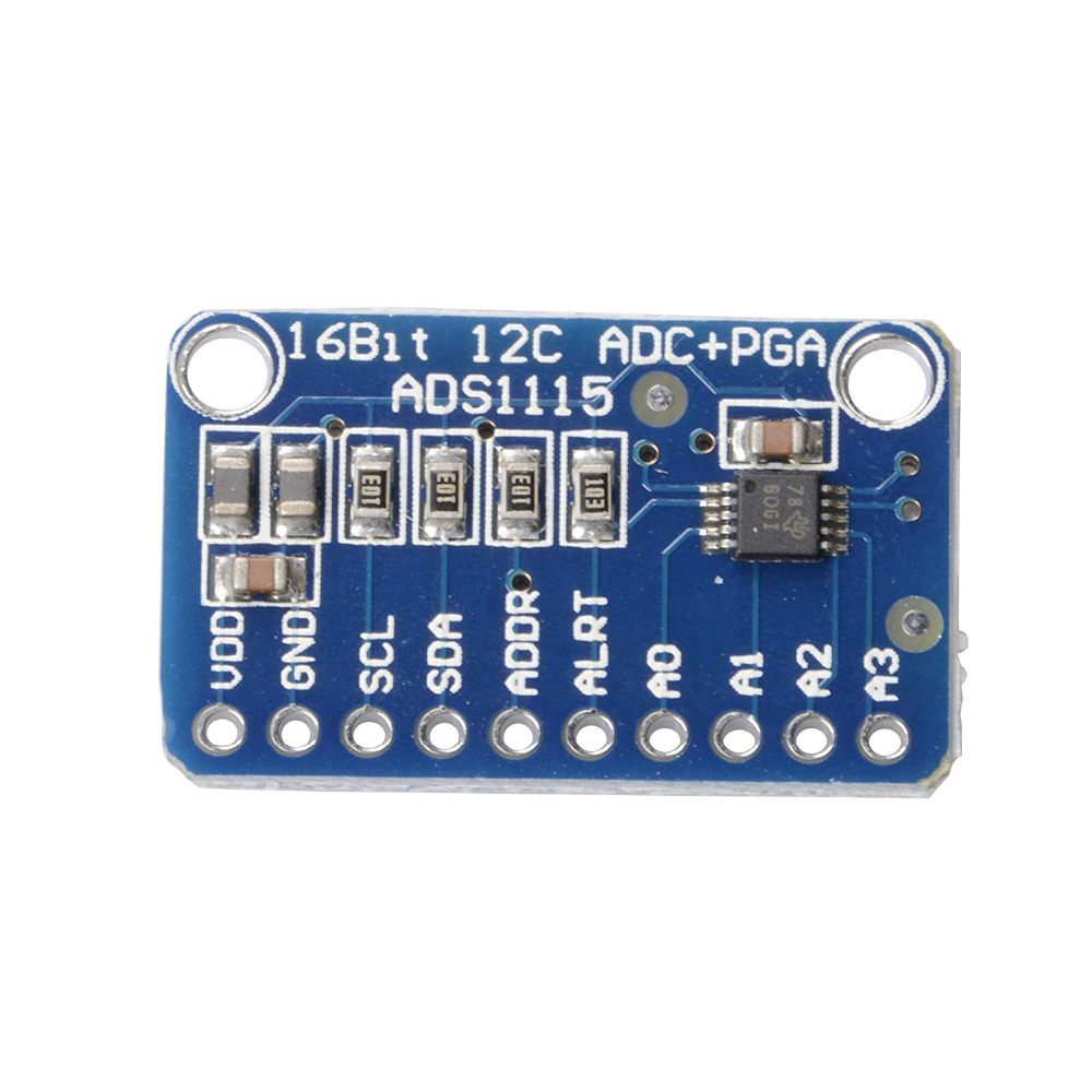
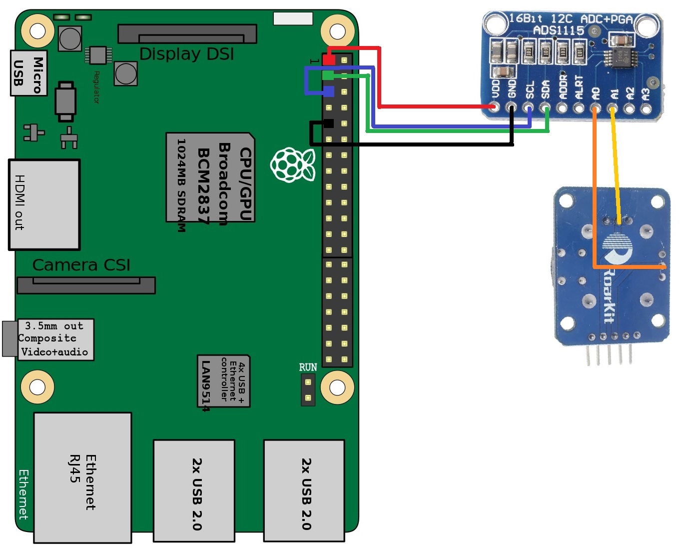
The module was soldered to the Game HAT and attached to it using 3M tape. The readings are taken from the middle legs of the variable resistors on the joystick. It looks like this:

The joystick is similarly soldered into the Game HAT. The wires are soldered to the Game HAT connectors, which correspond to the power and I2C connectors on the Raspberry. Wiring diagram:
At this hardware collection of the control panel is completed. Outwardly, he did not undergo any visible changes.
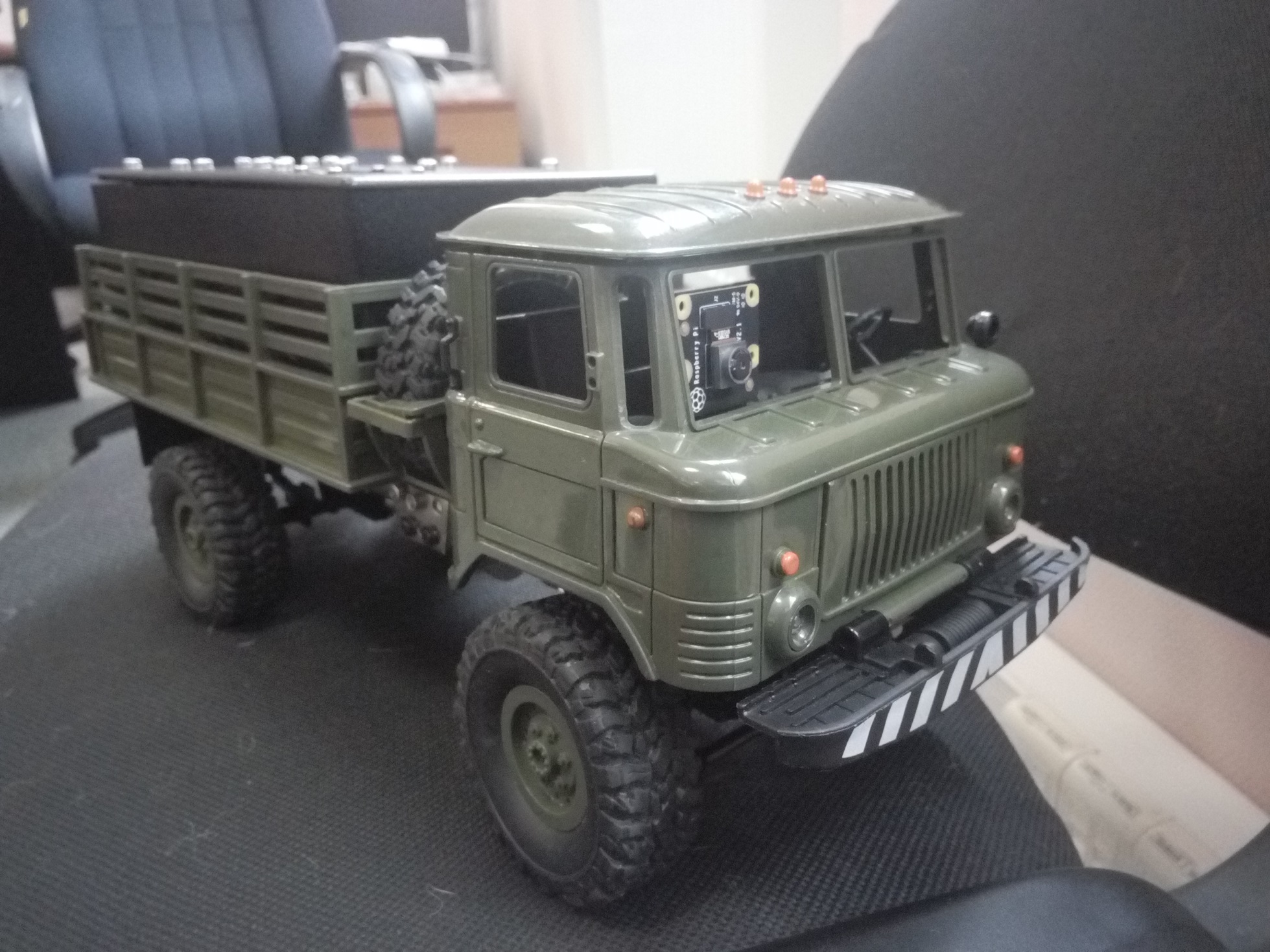
1.2 Machine
How it all looks awful under the hood:
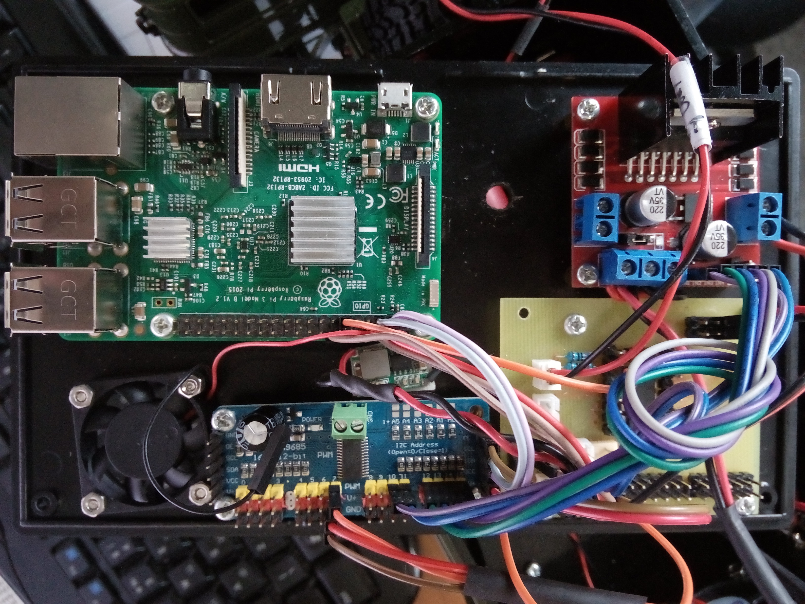
Let's get it right.
Components:
- Raspberry pi 3
- Raspberry Pi Camera v2 NoIR
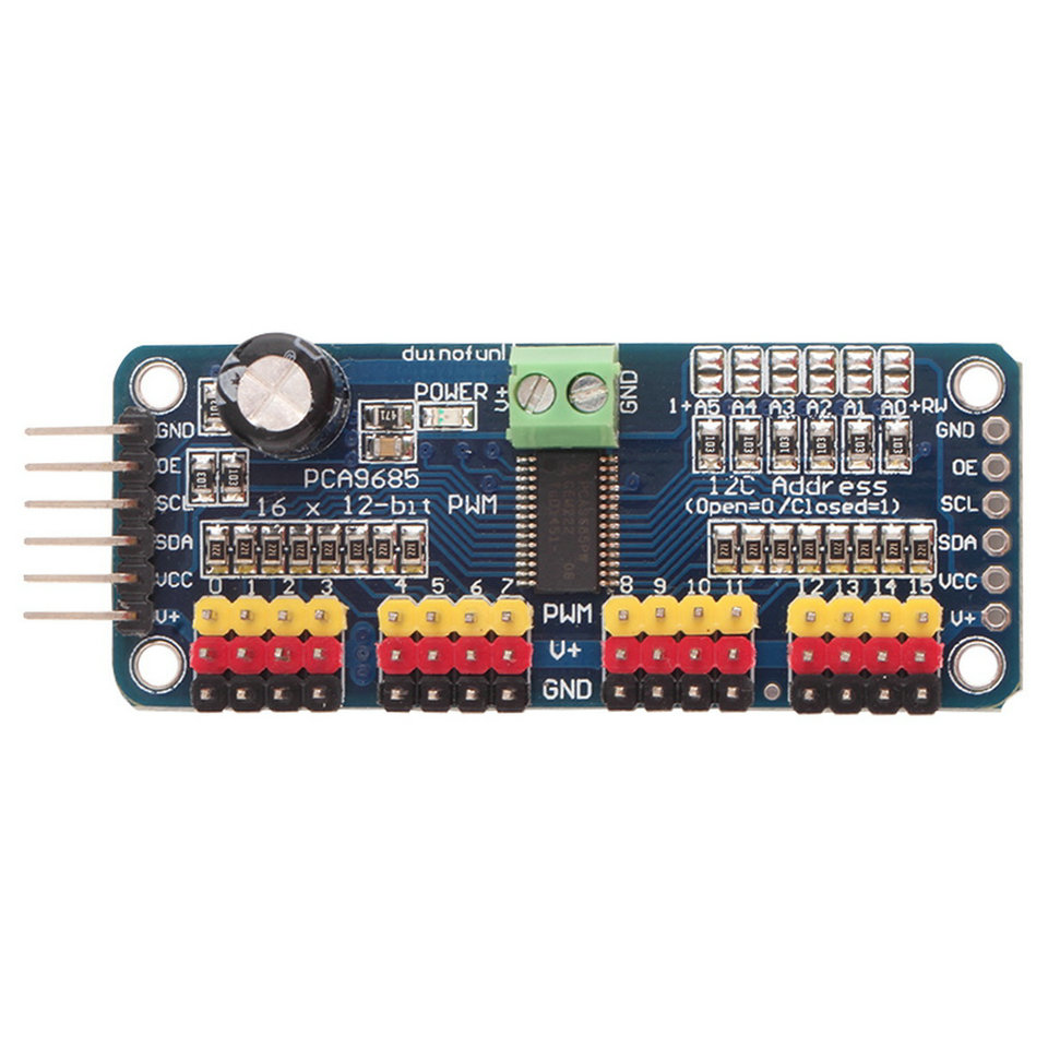
- PCA9685 PWM Generator
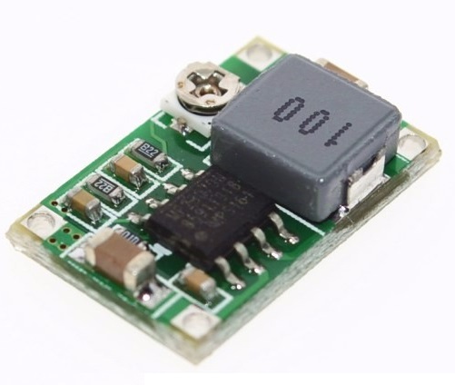
- Mini-360 step-down power converter
- BMS CF-4S30A-A charge controller
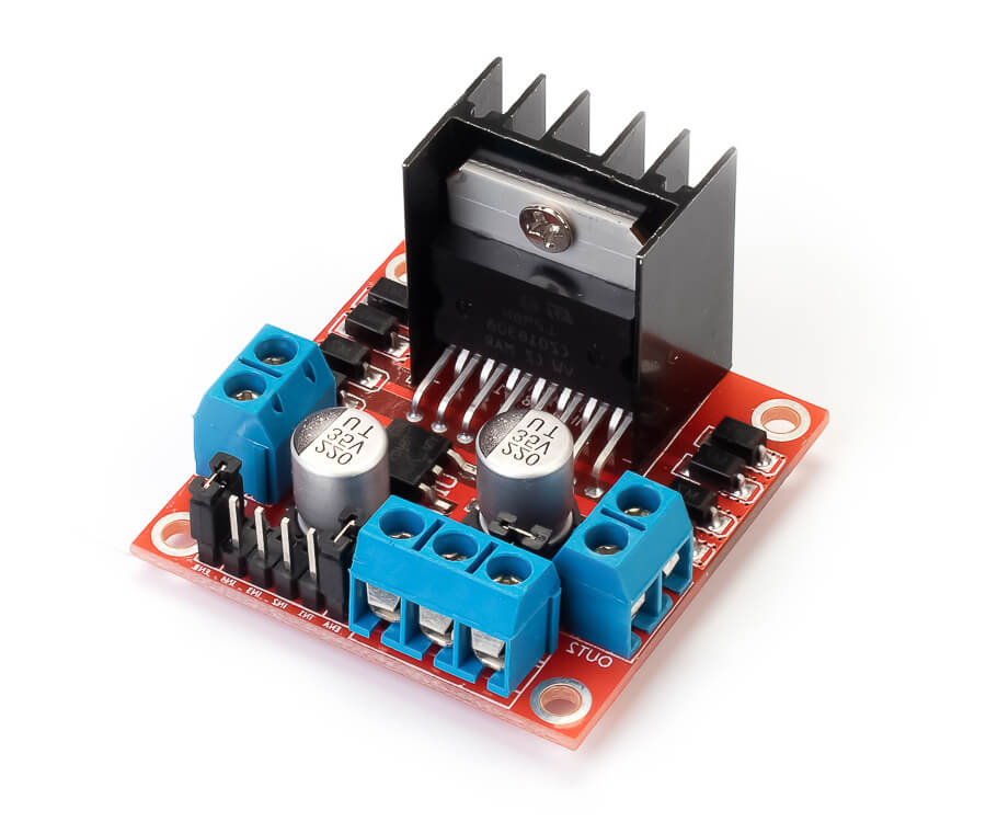
- L298N motor control driver
- My light control board based on L293 driver
- 3 lithium-ion batteries 18650
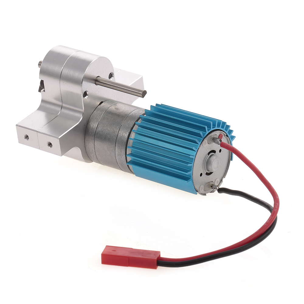
- 370 motor
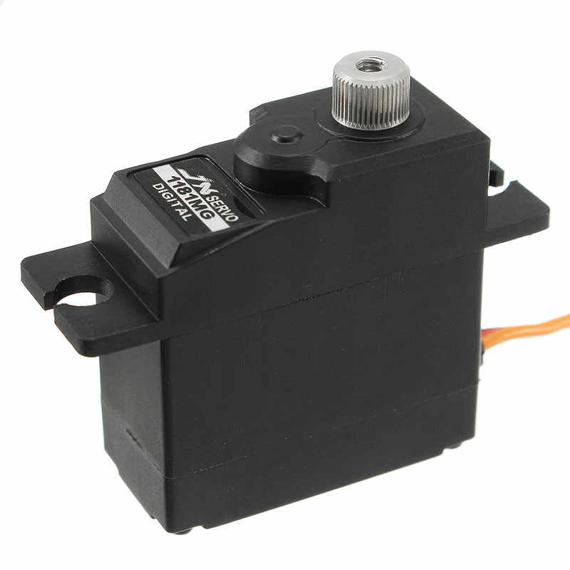
- DI-1181MG Servo
Nutrition
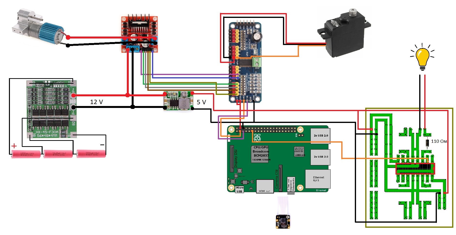
Let's start from the power supply, it is provided by three 18650 batteries connected in series and giving ~ 12 volts.
The batteries are connected via the BMS CF-4S30A-A board so that they can be charged and not discharged to zero on the pokatushki.
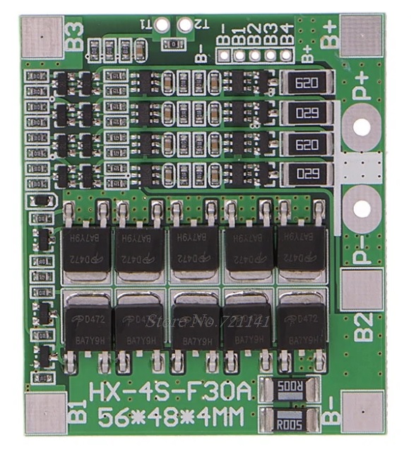
But this board is designed for 4 batteries, so it was redone to work with 3 batteries. Why was she taken, and not 3S 40A BMS. Because she was at hand.
Alteration scheme:

This voltage feeds the 370 motor through the L298N driver.
To power the Raspberry, the voltage from the same batteries is used, but the voltage is reduced by the Mini-360 module to 5 volts.
Raspberry powered right on its legs.
Motion
Now let's talk about how the car drives. To control the steering mechanism, a DI-1181MG servo drive is used, which is controlled using the PCA9685. PCA9685 is also responsible for controlling the motor by adjusting its speed and direction of rotation through the L298N driver. Raspberry also controls the PCA9685 on the I2C bus. The PCA9685 is powered by 5 volts with a buck converter. This is enough for servos and motor control. The motor is connected to two L298N outputs to increase power.
Video
For the video I used Camera v2 NoIR, it easily connects to Raspberry. But there were some improvements. The standard loop of the camera was 15 cm long. Which was not enough for installation work. This loop is also non-standard, it has 15 pins. On aliexpress, for one long loop for this camera, the Chinese want more than 1000 rubles. Therefore, a set of 10 standard 16 pin loops ~ for 300 rubles was purchased. And with the help of high-tech technology for the use of stationery scissors, a 15-pin cable for the camera has been redone.
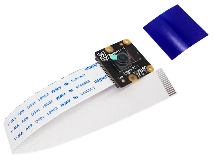
At the time of writing, the 2nd month I am waiting for the mount for the camera in the cabin. So far, the machine shows only the ceiling)
Shine
The machine has already installed regular light, consisting of headlights with 2 yellow LEDs. It remains only to power them.
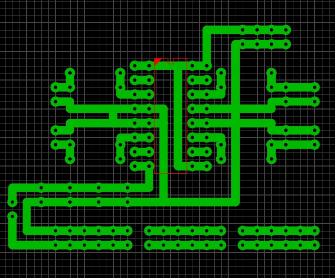
The light is controlled through my board, which is based on the L293 driver. Power to the diodes is supplied through a resistor. The board is made using LUT technology. It also has a bunch of tracks for power wiring.
It would be possible to use PCA9685 to control the light, at the time when I was doing my own I did not know about PCA9685 and could do without it.
Circuit board:
I will present the general connection diagram:
But this is what stood in the typewriter until I climbed))

By the time of writing, he had already begun to forget what he was doing and how. Although no more than a month has passed since the mount.
Everything is in hardware. In my next article I will describe the software part of how animated iron.
Thanks
My work colleagues: Andrei and Nikolai for help with iron, Anton and Eugene for helping with the video. Samodelkin-22 for LUT of my board. And Murzik.
References
All Articles