Homemade LED indicator in slim factor
Why is it needed
Recently, I wrote an article about a homemade bluetooth bike computer . It was a lively discussion. One of the proposals for modernization was the idea to add an indication or LCD screen. I liked the idea. And I decided to think about how to bring it to life.
Since the cycle computers were already made, the case was almost completely occupied, the option with the LCD screen fell off. I needed a size of 40x30mm, taking into account all the cables and wires, and no more than 2-3mm in thickness. Also there are some free conclusions. Various LED indicators (three digits, scale) did not fit. Then a very good idea came to mind - to make a homemade indicator from SMD LEDs. Take a thin one-sided PCB, place on it the right amount of LEDs, in the right order and you get an excellent indicator. Having imagined that all the LEDs needed to be wired, I decided that a cheap microcontroller would fit on the board, which would control all the LEDs on its own, and that the main computer of the cycling computer would control the indicator using one wire.
The result was a very compact (only 3mm thickness) indicator. Management by one wire, and 2 more for food. If you have ready-made devices, or you plan to make a device, and you need an indicator, then a homemade indicator is the most excellent option. We will analyze in more detail how it works.
20 LEDs on 10 pins - easy!
MK I chose the most inexpensive - SMT8S003, the same as in the cycle computer. He has only 20 legs. If you remove the legs of power and control, then there are 14 legs. The first task that had to be solved was to manage these legs with as many LEDs as possible.
A decision immediately came to my mind that you could hang 2 LEDs on one foot, one pin on GND, and the other on VDD. For each LED on the resistor. According to this scheme.
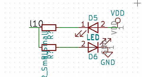
To manage is simple. We feed to pin 0, one LED is on, we feed 1 - the second LED is on. Translation into the third state (input) does not burn any. It turns on 14 pins, you can hang 28 LEDs. Not bad.
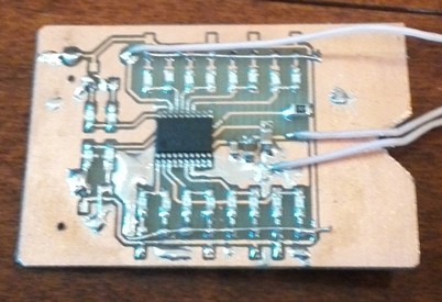
The son drew the indicator itself. For the bike computer, the most useful type of indicator, after the numbers is the scale. The indicator consists of 2 scales of 8 LEDs, and another 4 different status LEDs. Total 20 LEDs. I quickly sketched the board, etched it, soldered it, and started testing.
Turn on MK, all the findings in the third state, nothing should be lit. And ... LEDs are on. Of course, they have enough voltage of 5 volts to dimly glow. So it will not work, we change the scheme ...
More LEDs
A little thought, came another idea. Connect the LEDs not to the power and ground, but to two more terminals of the MC. Then you can just turn off everything. We try, it works fine. Due to the dynamic display, everything blinks beautifully. You can control each LED.
As a result, the following scheme came out for the future:
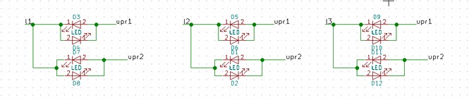
Select several control pins and workers. We put the resistors only on the controllers upr1 upr2. Thus, the layout and trace of the board are greatly simplified. 14 pins can accommodate up to 96 LEDs. 6 managers and 8 workers, plus 2 LEDs each. More than enough, the hand solder gets tired.
As it turned out, you can and more. Charlie Allen went even further, placing several LEDs between the control pins. Thus, it can be placed on 16 pins with up to 16 * 15 LEDs. But, many resistors are added to its circuit, and it is also necessary that all the LEDs are of the same color, in general there are some minor problems. Conclusion - 96 LEDs are more than enough.
We control each LED separately
To control each LED, the dynamic indication method is used. At one time, you can light one LED per control output. Next you need to go through all the pairs, these are indication states, and so on in a circle. Since the board has already been made, I redid it into one control pin and one resistor. It turned out 20 LEDs on one output and 10 working conclusions. Total 20 states.
To reduce energy consumption, MK operates at a frequency of 2 MHz. To go through 20 states with a frequency of 50 Hz at least, you need a timer with a frequency of 1000 Hz. Additionally, I also wanted to control the brightness. But it turns out that in order to lower it 10 times, you need a frequency timer of 10 000 Hz, and 100 times 100 000 Hz. In this case, in the interrupt handler, you need to go through all the options and light the desired LED. In general, MK could not cope. I had to switch to the option with PWM modulation.
We control the brightness using the PWM timer
The result was a simple program. We use one timer - TIM2, with the possibility of PWM generation. Adjust the timer frequency to 1000Hz, and the maximum value of the timer 125 - the width of the PWM, which will determine the gradations of brightness. As a result, you can set any brightness value from 0 to 125. At the moment when the second timer interrupt is triggered, in comparison with filling the PWM, we turn off all the LEDs.
The result was a great indicator. By adjusting the brightness, the consumption in the active phase is from 1 mA to 4 mA.
We connect cycle computer
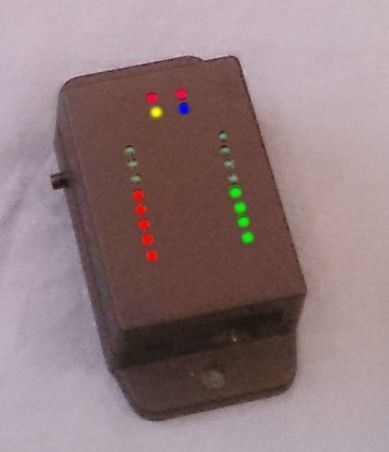
The indicator itself is ready, in the case of the cycle computer it looks like this:
To control the indicator, I chose the 1-wire protocol. I will not describe it. I can only say that I had to suffer in order to have time to process the interrupt and withstand the necessary timings, but in the end everything worked. Cycle computer as Master, and indicator as Slave. To control, you need to transfer 4 bytes. The first byte is the command, brightness and one bit to go to sleep, the remaining 3 bytes are LEDs, bit by bit on the LED.
The first thing that occurred to display on the indicator is speed and cadnes. Service LEDs should be left for bluetooth status, speed control and cadence violations, and one more - distance control.
After the trial, added the ability to display the remaining distance from the set or the remaining calories from the set. It turned out very convenient. You make a plan to spend 2000 Cal for a walk, you go and you see right away, there is still half left. Conclusion - an indication of the thing is useful.
My son loved it, he set about trying to make a key chain - an indicator with a battery in epoxy resin. Went to think.
What other indicators can be made
Hours - LEDs in two circles - hours and minutes.
The sides of the world are for an electronic compass.
Scale for incremental rotary encoder.
Several scales in one indicator.
Heart for music postcard.
8x8 matrix for displaying pictures.
Thin seven-segment indicator for one digit 11 LEDs.
In general, there are many ideas on how to use it.
On github , as usual, the board, program, implementation of the 1-wire protocol and dynamic display. Who needs, you can use in their projects.
All Articles