Semi-automatic well pump control
Semi-automatic control of the well pump using the STM32 in Arduino environment
Many owners of household plots have water wells on their holdings, and may have been faced with the problem of watering of the well / water penetration during well shutdown from autumn to spring.
It so happened that the well in my area was idle for several years, and when used, they took very little water.
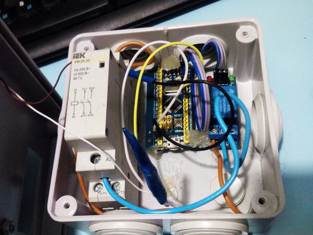
Having tried to clean it in various ways, it was realized that everything is not so bad and it is enough to ensure stable water withdrawal. To do this, a simple device was assembled, consisting of a power supply with a micro-usb adapter, (a charger from the phone, not in the photo), a blue pill board based on a pebble stm32f103c8t6, a relay module, a bipolar magnetic starter, a conventional closed push-button switch, and assembled in the terminal box.
The microcontroller board was prepared by the HWman manual . In the comments there was a request to clarify that the STM32 can be flashed with a special bootloader, which later allows you to program it via USB, just like ordinary arduinks.
I program with a plugin in the Visual Studio Community. Installing the plugin is primitive, does not amount to any mental labor. I will add only that the plugin requires the installed ARDUINO IDE. Professionals, I think, will confuse this approach, but the finished product has been working steadily for more than six months and fulfills the task. And yet, I am open to cooperation on ideas for improving the device.
We get a very convenient environment with the syntax analysis of the code, IntelliSense, and that is subjectively important - a dark theme. For little eyes.
We sew to a scarf:
Code
/* Name: Nasos.ino Created: 23.02.2017 19:08:20 Author: Ksiw , () . , 10 . , , , 20 /. 99% delay() */ unsigned long Work = 2UL*60; /*2 */ // , // ... ! . const unsigned long Sleep = (unsigned long)20*60; // unsigned long TimeLeft; // int tempo = iter; // int iter = 10; // unsigned long timeNextSwich; int button = PB4; // unsigned long WorkTime, SleepTime ; // bool handOn = false; // bool flag; // int RelayPin = PB7; // unsigned long PreviousMillis = 0; unsigned long CurrentMillis = millis(); unsigned long fullTimeIteration = 4200000000; // //(long 4,294,967,295) //--------------------- void SwichFlag(); void SwichRelay(); void Button(); unsigned long SecToMillis(unsigned long); void ResidueTime(); void ResetTimeToWork(); //------------------------------------- --------------------------- void(*resetFunc) (void) = 0; //*************************************************************************** void setup() { Serial.begin(115200); flag = false; // //----------- pinMode(RelayPin, OUTPUT); pinMode(button, INPUT); digitalWrite(RelayPin, flag); Serial.println(""); WorkTime = SecToMillis(Work); SleepTime = SecToMillis(Sleep); PreviousMillis = millis(); } void loop() //************************************************************************** { while(true) { CurrentMillis = millis(); // ResetTimeToWork(); // milis() SwichFlag(); // SwichRelay(); // , ResidueTime(); // Button(); // tempo++; handOn = false; delay(100); } } //------------------------------------- ---------------------------------------------- void SwichFlag() { if(flag && CurrentMillis-PreviousMillis>=SleepTime) { PreviousMillis = CurrentMillis; flag = false; // , Serial.println("Flag On"); } else if(!flag && CurrentMillis-PreviousMillis>=WorkTime) //, , "" { PreviousMillis = CurrentMillis; flag = true; Serial.println("Flag OFF"); } } //------------------------------------- ------------------------------------------------------- void Button() { if(digitalRead(button)==HIGH) // { do { if(handOn) { delay(50); continue; } Serial.println("TURNED ON"); digitalWrite(RelayPin, LOW); // flag = true; handOn = true; delay(100); // }while (digitalRead(button)==HIGH); CurrentMillis = millis(); // PreviousMillis = CurrentMillis; // delay(20); } } //------------------------------------- --------------------------- unsigned long SecToMillis(unsigned long Temp) { return Temp*1000; } //------------------------------------- ---------------------------------------------- void ResidueTime() { if(CurrentMillis<PreviousMillis && tempo > iter) { if(flag) { TimeLeft = timeNextSwich/1000+1; Serial.print(" Time to ON: "); Serial.print(TimeLeft); Serial.print("sec"); Serial.println(""); } else { TimeLeft = timeNextSwich/1000+1; Serial.print(" Time to OFF: "); Serial.print(TimeLeft); Serial.print("sec"); Serial.println(""); } tempo = 0; } if(tempo > iter) // { if(flag) { TimeLeft = (PreviousMillis+SleepTime-CurrentMillis)/1000+1; Serial.print(" Time to ON: "); Serial.print(TimeLeft); Serial.print("sec"); Serial.println(""); } else { TimeLeft = (PreviousMillis+WorkTime-CurrentMillis)/1000+1; Serial.print(" Time to OFF: "); Serial.print(TimeLeft); Serial.print("sec"); Serial.println(""); } tempo = 0; } } //------------------------------------- milis(); void ResetTimeToWork() { while(CurrentMillis<PreviousMillis) // { if(flag) // { timeNextSwich = SleepTime-(4294967295-PreviousMillis); // while(timeNextSwich>=CurrentMillis) // { CurrentMillis = millis(); ResidueTime(); Button(); // , ResetTimeToWork()! if(CurrentMillis>PreviousMillis) return; tempo++; // ResidueTime(); } flag = false; PreviousMillis = CurrentMillis; // CurrentMillis = millis(); return; } if(!flag) { timeNextSwich = WorkTime-(4294967295-PreviousMillis); while(timeNextSwich>=CurrentMillis) // { CurrentMillis = millis(); ResidueTime(); Button(); if(CurrentMillis>PreviousMillis) return; tempo++; } flag = true; PreviousMillis = CurrentMillis; CurrentMillis = millis(); return; } } } //-------------------------------------- -------------------------------------------------- void SwichRelay() { if(!flag) { digitalWrite(RelayPin, flag); // } else { digitalWrite(RelayPin, flag); // } }
With regards to the code. The program was written in several approaches, modifying in the course of identifying shortcomings. It looks rather confusing, but I will try to clarify.
Works as follows:
0) The program architecture is designed to interrogate any external device (button, pressure sensor, timer, etc.) and set the flag to turn the relay on or off, and then, with a separate function, check the flag status and switch to the appropriate position.
1) The program code rests on the millis () timer function, the ResidueTime () function calculates the time of the next relay switching, SwichRelay () checks the status of the flag and gives the switching command, if necessary.
2) The relay turns on when a low level signal is applied from the PB7 foot. When you turn on the device, after initializing the MK, the relay switches to the ON position, applying voltage to the starter coil, which in turn energizes the pump.
3) The device operation time is 2 minutes, after which it goes into standby mode for 20 minutes.
4) Turning on the switch is processed immediately, and after turning off the program withstands an idle interval of 20 minutes. This is done to ensure that the well replenishes the pumped water, and to exclude the case of running the pump dry.
5) Also in the code there is a function ResetTimeToWork (), which is triggered when the millis () function overflows, which
Returns the number of milliseconds since the start of the current program on the Arduino board. This amount is reset to zero, due to an overflow value, after approximately 50 days.
(from the site Arduino.ru)
Therefore, in order for the device not to “fall” after this period of continuous operation, the above-mentioned function has been developed that ensures stable operation of the device without an additional restart.
Getting to the collection scheme.
Assembly scheme:
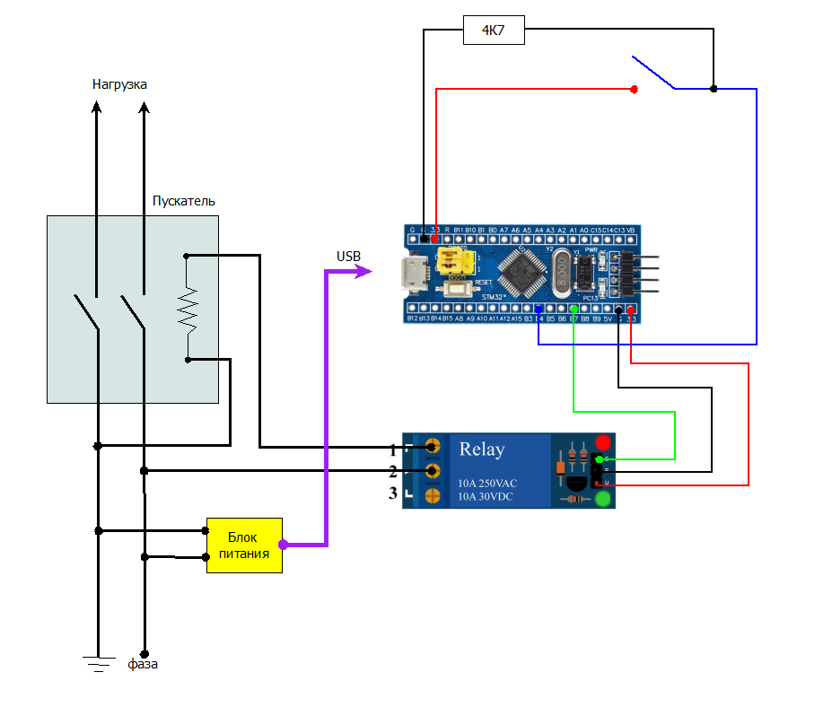
The signal from the PB4 foot must be pressed to ground with a 4.7KΩ resistor, otherwise the relay does not work correctly.
In the box install dinreyu for starter:

And we mount the remaining parts, fixing their position with the help of hot snot, as in the first photo.
In the cover it is necessary to cut a hole for the starter, it is higher than the depth of the box.
Do not forget to install the power supply for the board, you can hide it inside the box, there is still enough space in it, or take it outside and plug it into the nearest outlet.
The finished device, it remains only to put on the terminals of the starter cable 230V and connect the load.
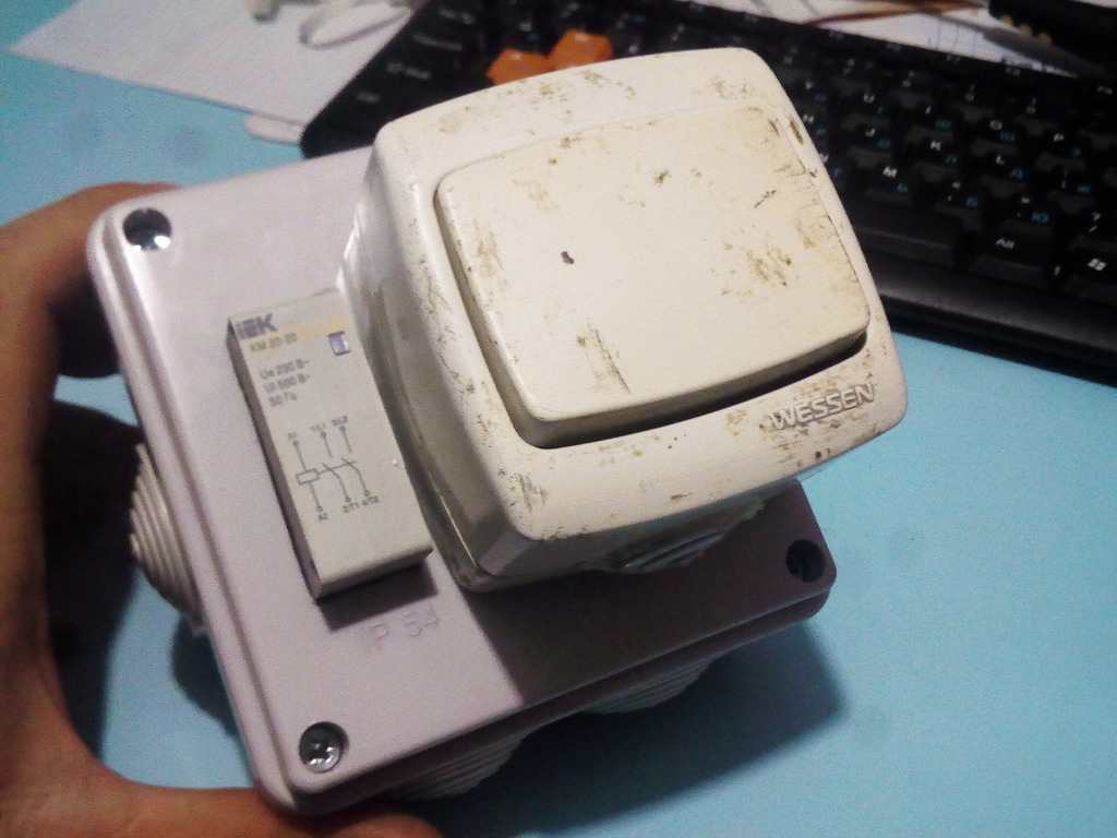
The switch used the old, he also stood on turning on the pump. Outside it has unavoidable contamination with cement and other scuffs, but it has a hermetic case, inside it is completely intact and will work in the garden for a long time. Given the meager switching current - almost forever, until it breaks mechanically.
Thanks to HWman 'for the submitted article on ensuring the work of stm32 in the ARDUINO framework.
Archive with a sketch attached .
All Articles