How to make tea by MQTT or an affordable smart socket with temperature and current control
What for?
Even in this hub, there is an increase in interest in IoT, in my subjective opinion this is a global trend that goes far beyond this site. So it’s worth inserting your 5 kopecks into the development of the direction, especially since the idea to make a node for a smart home, which could control the consumption of any device powered from 220V and made it possible to program the control logic depending on the parameters of consumption, temperature, phase, spun long ago. moons, etc. There are ready-made solutions, but often they are not satisfied with something, and ready-made is not our method if you can try to build your unique bicycle.

Parameters of the future bike:
- Cheap device from publicly available components.
- Current control in the consumer circuit.
- Device control via MQTT protocol.
- Device temperature control.
- Two remote sensors to monitor the temperature of the consumer.
- Status indication on the device screen.
- Emergency shutdown of the consumer if the temperature or current exceeded the specified values.
Application Case:
- Monitoring electricity consumption.
- The possibility of remote shutdown of the device in case of an accident or just like that.
- A simple device for monitoring the temperature in semi-professional server storage rooms where emergency situations often occur as the temperature in the room is not monitored.
- Thermostatic control (maintaining the temperature, in my case, I need to predict the thaw and turn on the heating of the shower with a “heating cable” in advance).
- Smart home system node for the implementation of the above functions.
-
And of course the wifi maker!The rest is for the quantity.
And I would like to show how simple and cheap it is to implement the bundle: [Device] <-> [Wifi] <-> [MQTT] <-> [Centralized state tracking and endpoint control].
Component selection
How to measure the current?
Unlike voltage measurement, sensors for measuring current are not so common in amateur electronics. But several types of current sensors are available - current shunts, transformer type and Hall effect sensors. It is clear that the classification is amateur, but if you look at the online store, the names will be approximately the same.
We didn’t want to use a shunt because of the need to invent a galvanic isolation (it’s so that 220V doesn’t rush into our microcontroller with all its amps and all the magic smoke on which they are known to work) didn’t come out of it. Transformer sensors also have their own characteristics. But the latter type was not only very affordable, but also easy to use. I thought so when I ordered it.
If you have a low voltage circuit, then it is wise to use a small known nominal resistor instead of a shunt. Read more about how and how you can measure the current in the good article by the author radiolok .
The ACS712 sensors are most often sold already soldered to a small board with the required minimum of strapping. I can advise before use to protect the chip itself with a metal screen from the influence of extraneous magnetic fields. The sensor to them is very sensitive and, in stock form, is more suitable for searching for hidden wiring than for measuring current. With improvised protection, noise immunity increases significantly.
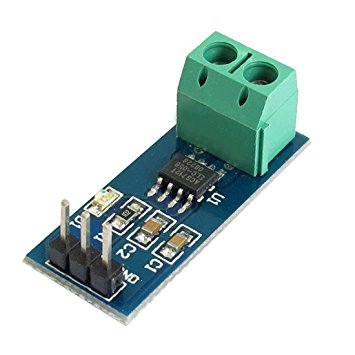
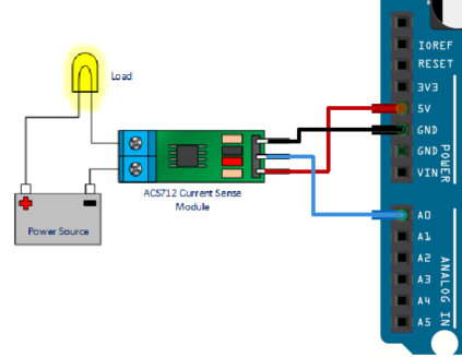
In the big green connector we stick two wires obtained by cutting one of the two wires of the 220V circuit (series connection in the circuit). On the connector on the other side of the sensor, we supply + 5V, earth, and from the remaining pin we remove an analog signal that oscillates about the middle (2.5V) depending on the strength and direction of the current. Everything is so simple ... on paper.
Main unit module
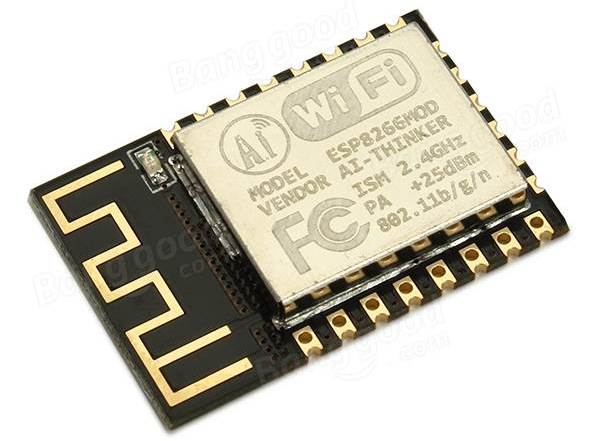
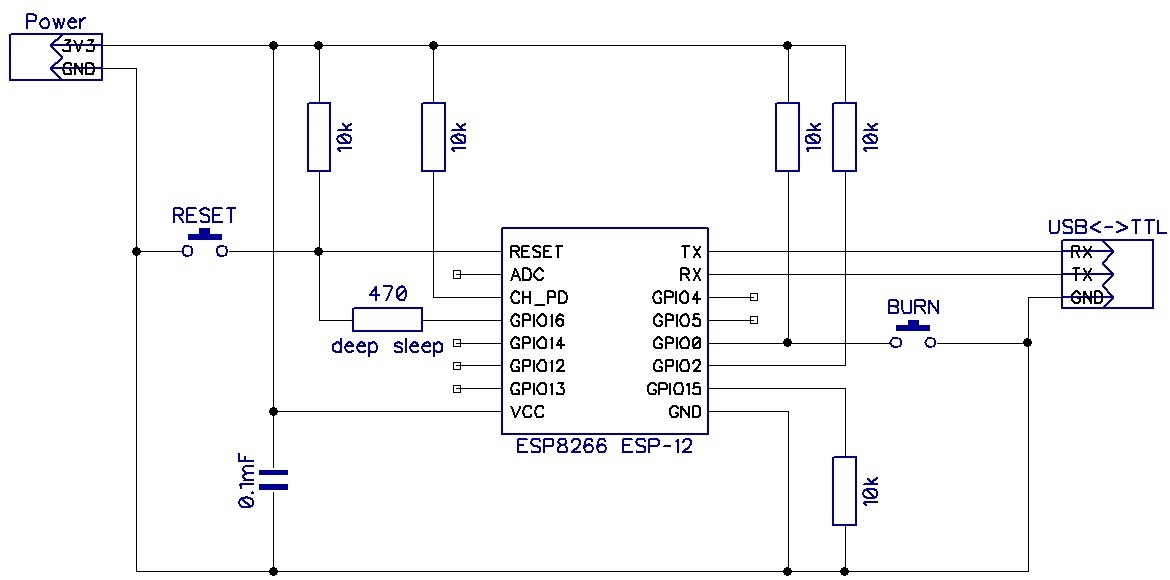
From this module it is required to maintain communication, preferably via Wifi and twist the main working cycle with interrogating sensors, checking conditions, responding to buttons, etc. What to choose from one option? And suddenly we choose ESP8266. In my case, this is ESP-12F. Oh yes! There are still ESP-32.
It is best to take it immediately soldered to the board with strapping and USB to UART adapter. But you can connect yourself as well as buying ready is not according to the precepts of cycling. Material on this topic .
I lost some amount of time trying to flash a self-connected ESP-shku. Used USBtoUART on the CH340 chip. The board stubbornly did not want to flash until I switched the CH340 logic to 5V at the risk of burning the ESP findings. But so far without loss.
Then it all connects to the Arduino IDE HWman and is not much different in programming from the usual Arduino. But it is very different in capabilities and computing resources:
- 80 MHz 32-bit processor Tensilica (English) Russian. Xtensa L106. Non-guaranteed overclocking up to 160 MHz is possible.
- IEEE 802.11 b / g / n Wi-Fi. WEP and WPA / WPA2 are supported.
- 14 I / O ports (11 of them can be used), SPI, I²C, I²S, UART, 10-bit ADC.
- Power 2.2 ... 3.6 V. Consumption up to 200 mA in transmission mode, 60 mA in receive mode, 40 mA in standby mode. The mode of reduced consumption while maintaining the connection with the access point ~ 1 mA, deep sleep mode 0.1 μA.
ru.wikipedia.org/wiki/ESP8266
Why Arduino IDE? I am aware that there are at least two ways to implement all the same thing, it is to use the firmware with scripts on LUA and native development in C using the SDK from the manufacturer. The first method seemed to me to be very superficial, I think I could not have realized some nuances by following this path. The second method is the most promising, but it takes a lot of time to master, but this is the only option if you intend to implement a more serious device.
Using the Arduino IDE the most important part was the least troublesome in terms of inclusion in the project. However, normal debugging is not enough. Initially there were doubts that all conceived functions together (1-Wire, i2c, ADC, MQTT, EEPROM, wifi) will coexist on ESP-12F in one sketch, but rolled.
Stm8s103f3p6
Why would there be another microcontroller? Just today, a single-core device is no longer taken seriously, just kidding. The reason is different - the current sensor is so “special” that it is easier and cheaper to hang up all the processing of its readings on a separate microcontroller and let it nurse it. In fact, we received a digital current sensor that is connected via the i2c bus. Theoretically, you can use the cheapest microcontroller, but since these boards are very affordable and quite decent in terms of parameters, I applied it. In the future, I intend to use them, as a replacement for the PIC12 that I used to add “brains” to completely different crafts. At first, I thought this idea was excessive, but now I see that there was no need to waste time on the other option.
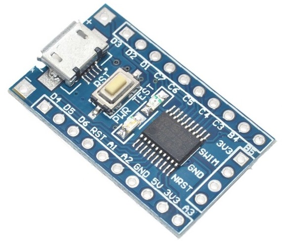
These microcontrollers are programmed in the IAR Embedded Workbench environment, it is free for code up to 8kb, our microcontroller has so much memory. A huge advantage is the possibility of human debugging. True, we need to wean ourselves off using the usual C standard functions like printf and working with floating point numbers, as this will quickly wipe out all the memory. More about the firmware will tell below.
Screen
There is almost no options here - we use OLED SSD1306, an excellent screen with a very beautiful glow and simple connection. Library for it is even under the Spectrum. There are screens of different colors. There are also boards on which immediately soldered and ESP and a similar screen. Blue color seems the most advantageous. There are two-colored when the top of a different color.
The screen is connected via i2c bus, this is only 4 wires with regard to power. The current sensor will also be connected via the same bus. The screen did not deliver any problems at all. Definitely a must have!
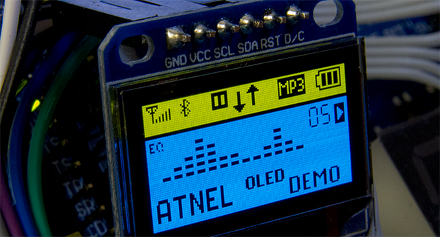
It is worth considering that the screen is likely to shine 24/7, and the screen technology is such that the individual LEDs-pixels fade over time, so you should try to use them evenly. I thought of simply shifting the image in different directions at regular intervals. In general, I think if suddenly the image becomes completely unreadable, replacing the screen is not a problem. Let's see how much he will live.
Detailed video about such a screen and standing youtube channel.
Temperature sensors
I used the well-known DS18B20. In the parasitic power mode, the three sensors quietly work on one twisted pair of wires at a distance greater than what is reasonable for such a project (enough with a margin to any point of the apartment).
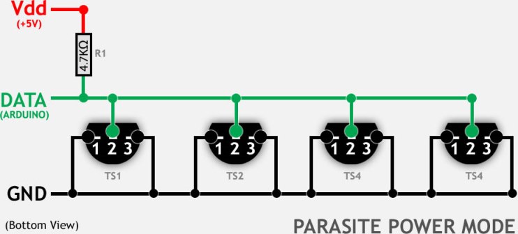
The only difference from the picture is the use of a resistor on the 1st Q, otherwise there is not enough power. When this happens, the sensor produces a temperature of 85 degrees. Request for conversion and subsequent reading of the value occurs sequentially for each sensor, so that they do not interfere with each other.
I considered the addresses of the sensors in advance and zahardkodil them in the sketch. There was an attempt to auto-detect sensors on the bus, but I did not like the stability of this algorithm, and since the temperature parameter is responsible, the game is not worth the trouble.
Structural elements and "spreading"
All this iron was placed with a small shawl box that can be picked up on any radio market to taste. Usually used contact relay for 220V. Many kilometers of wire from the old FDD cable, half a kilo of resistors at 10KΩ, a couple of buttons, a pair of leads under the “tulips” for connecting the 1-Wire line and ADC ESP-shki. A lot of hot melt glue. One high-quality power supply for 5 volts, which was entirely placed in the housing of the device. And alas, almost no blue electrical tape.
If you are collecting a prototype, try not to place anything on one of the covers, then it will be convenient to remove it and pick it up in the device. Consider from where the external connecting cables will fit and what kind of connectors they have, so that it does not work out that you need to plug the plug at wild angles, etc.
Component costs:
- Current sensor - $ 2.1
- ESP-12F - $ 3.2
- Stm8 board - $ 0.75
- Logic Converter - $ 0.5
- Temperature sensor - $ 0.6
- Screen - 4.2 $
- Relay - $ 0.75
- Box and other dusting ~ xs, let it be $ 3
Total: $ 15
Armed with the right file ...

Current sensor
As I wrote above, the current sensor turned out to be very capricious. Furthermore, measuring the effective value of an alternating current is somewhat more complicated than measuring the value of a direct current. I think better these moments will be explained by a person who is well versed in the issue of radiolok :
Video
And further:
“Instead of I (current), substitute U (voltage) in the formula. The integral is the area of the figure under the envelope. It is possible to calculate the integral approximately by the method of medium rectangles, approximating the figure with rectangles with a height equal to a discrete sample of the voltage value and a width equal to the time interval between the samples. ”
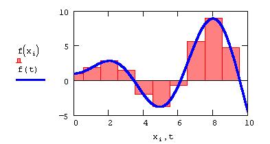
Thus it turns out that we need to measure the area "under the graph" of alternating current for one period. Since the frequency of our voltage is 50 Hz, we get a period of 20ms . When starting to measure does not matter, the main thing is to do it over a time multiple of 20ms . Practically everything comes down to summing up the ADC readings in absolute value over a period with the subsequent calculation of the average. This will be our current. For the period between the two measurements, the response time of the ADC is taken, it is quite stable.
As a bonus, this method allows you to measure both alternating and direct current. Behind the brackets we leave the probability of the walking frequency and voltage in the outlet.
You can try to do measurements on the ESP8266 ADC and I tried it, but the accuracy turned out to be very mediocre, and most of the time ESPnash had to deal exclusively with signal processing from the ADC. In addition, the built-in ADC has a range of measured voltage of the order of 1 volt. You must use a voltage divider. ESP is powered by 3.3V, and the current sensor is from 5V, this means that data from the ADC can be distorted if the power supply changes its value out of proportion. All this does not add accuracy to measurements. The initial plan was this - if it does not work out normally using the ADC ESP, then use a separate microcontroller, and that’s what happened.
With the use of Stm8s103f3p6, the situation is greatly improved. Firstly, both the sensor and the microcontroller are powered by 5V, which does not allow the measurement results to “float” at voltage surges. Secondly, the microcontroller can devote all of its computing resources to signal processing, filtering and refining it. In fact, of course, not everything is straightforward; you can hang something else on it.
It was determined experimentally that in 20ms stm8 manages to get about 600 values from the ADC without compromising accuracy. If necessary, you can clock the ADC faster, but on the graph it becomes more deliberately false values. I monitored measurements using Processing software, this is a product for visualizing something, in my case it was a bundle of values taken from the ADC. I obtained fairly stable readings after measuring within 100ms, that is, approximately 3000 measurements. Then we multiply by an empirically chosen coefficient (I have no idea what this number is and how to calculate it because other numbers were obtained using all the appropriate formulas, I just adjusted everything) Then the value is passed through the filter . All that remains to be done is to put the next value in the place from where the ESP will take it.
The result was about this kind of stability if you turn on a 100W bulb.
In the process of debugging, it turned out that the sensor is able to hang when the relay is triggered, apparently from strong magnetic fields at the moment of opening the relay with the formation of an arc. I had to add a circuit "juggling" the sensor on the power. Although at first I thought it was stm8 freezing or some kind of block of it because there was nothing to hang in the sensor, but it could.
Due to the noise of the sensor, it is practically impossible to measure the current up to 100mA. Somewhere on the forums saw a mention that this is normal. I tried to organize the detection of noise and output, in this case, zero current readings so that the current did not jump even with an open circuit.
The algorithm of this detector is that the noise has an equal distribution of values above and below "zero", while the present signal in a specific part of the period still has an average value different from zero, unless of course we started the measurements at the moment of zero transition by a sinusoid. Therefore, I listen to the signal in three random intervals of the same period, which are located relative to each other in such a way that at least one of them does not fall guaranteed at the time of the transition by a sine wave of zero and gives a total value other than zero. Perhaps there is a simpler way, but cycling, you know, does not tolerate a long study of the issue.
Stm8 happens to hang, but only in the process of exchanging on the i2c bus with ESP, perhaps because of my not great knowledge of programming this microcontroller, and perhaps because it can. Using an observant dog helped solve this problem.
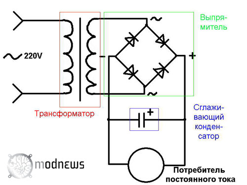
It is easiest to get a safe alternating voltage for debugging by disassembling a transformer power supply (naturally decreasing, preferably a voltage up to 12 volts) and disconnecting the diode bridge from the transformer and the smoothing capacitor, usually there is nothing else there.
It so happened that I did not have a device that can measure the effective value of alternating current. In this case, it is possible to manage by measuring the effective voltage across the resistor of a known rating, and the current can already be calculated by dividing the voltage by the rating of the resistor. The actual value of alternating voltage can show any multimeter. And the second way is to measure the voltage drop across the same resistor, but connecting it after the diode bridge and the smoothing capacitor. Naturally, in this case, the current value will be somewhat less because the AC / DC converter has its own efficiency.
Naturally, I mean that the above operations are carried out with a low alternating voltage, and not a network one.
In this article, I will not disassemble the programming process under stm8. But it is not difficult, there are standard libraries for the periphery and Google solves the lion’s share of problems. Those who do not want to go into details are invited to pour the firmware ( CurrentMeter (IAR) \ STM8S103 \ Exe \ Project.hex ) into the microcontroller and forget about it. If there is a desire to drip deeper, for starters, the article and video:
Video
There are attempts to adapt the Arduino for this microcontroller, but at the moment I have not found more or less ready for real use.
So, we have a current sensor with i2c interface. Since ESP has 3.3V logic and stm8 5V, a logic level converter is needed, and a two-way one, with a voltage divider that does not get off. Any tricks with the installation of sequential resistances allow something to establish a connection, but the stability of this solution is not satisfactory. It is much easier to use a ready-made two-way converter, which costs a penny.
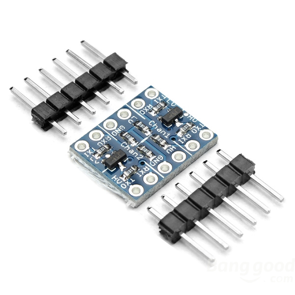
His work is based on the use of field-effect transistors, more information about the level conversion can be read here.
[ Firmware and source for stm8 ]
Assembly and layout of the device
The prototype of the device was decided to be assembled by mounting. There is a possibility that some points will have to be redone during operation, as well as I still have not mastered the normal and simple layout of printed circuit boards. After the device has been operating for several months without any modifications, it probably makes sense to develop and order printed circuit boards in China. In the meantime, turned out such a pasta monster:
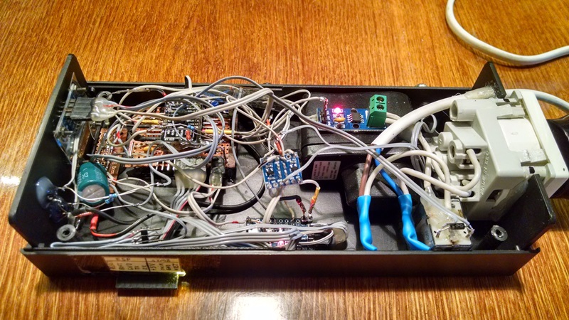
Intuitive and clear circuit switching elements of the device.
The general principle of the prototype assembly is simple - we mark approximately in a plastic box where it will be located, we fasten the main elements there and then everything is connected with a mounting wire. It is necessary to consider the location of the elements in order not to create unnecessary inconvenience.
Using the Chinese irreplaceable scan, the necessary (and not only) holes are made, the file for the screen is fitted with the file.

To power the electronics, a high-quality 5V power supply is used, which is connected in parallel to the 220V network directly inside the device.
It is very important to understand that 220V is already a dangerous voltage, make sure all connections are isolated and, if possible, localize such connections in one part of the device, and the low-voltage part in the other. With the first test connections, you can switch through a normal machine, no one is immune from errors.

About errors and the likelihood of making them. Nothing unusual, just slightly crushed thermonuclear bombs from hitting the ground in case of an accidental fall together with the plane after an unsuccessful refueling over Spain in the year 66. Photo from this article by MagisterLudi
The photo shows that the current sensor is glued to the power supply, I did not notice surprisingly noises from it, but noticed that the noise penetrates from above, I had to remove the sensor and shield it with metal foil. You can check the effectiveness of shielding by applying a neodymium magnet. It is only important not to forget that a voltage of 220V is applied on one of the sides of the sensor chip, therefore it is necessary to shield it with insulation
If someone does not understand the visual block switching scheme given above, there is a curved basic circuit. The first experience of using fritzing seems to be a lump.
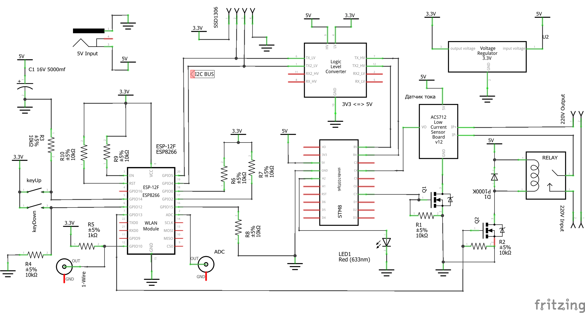
The only thing that is not reflected in the diagram is the output required for the firmware, contacts from ESP and STM8 to a separate connector on the side of the device. Thus you can finish with the assembly to begin to flash the finished device, and not a cross between the nodes and wires scattered on the table.
Ring the power supply for a short circuit or correct polarity several times before applying power. It seems simple things, but a small handful of dead handkerchief in the drawer of my desk eloquently requires not to neglect these simple rules.
Communication with the outside world.
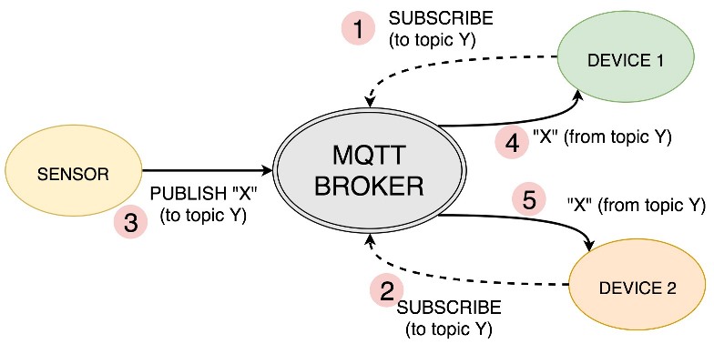
Let's start slowly finishing the software. For the organization of management and interaction with our outlet, we will use the MQTT protocol.
MQTT. How does it work? Everything is organized as follows - in the local (and maybe not in the local) network there is a certain host on which a special program ( MQTT broker ) is running that receives various data from various devices and organizes their storage in the manner of a file system and directory on your disk.
For example: “SmartPowerSocket1 / Current” - this is how the real MQTT topic looks.
The folder is a device - “SmartPowerSocket1” , subfolders are some internal parameters of the device, for example, the current value is “Current” . The full path to the parameter (topic) is used to subscribe devices to changes in these parameters. There is also a recording of the parameters by the device itself. You can subscribe to the entire “folder” (topic) and receive all changes of parameters for a specific device (topic or subtopics) - SmartPowerSocket1 / # .
More detailed video on this topic.
Video
And again I recommend this channel, there you will find a lot of useful information.
The most famous MQTT broker is Mosquitto . And since I decided to immediately deploy the MajorDoMo smart home control system, which was already featured in the video above, all this was picked up in bulk by deploying the finished image under the Orange Pi PC . There everything is already installed.
Using the MQTT protocol will make it possible to use different smart home control systems and not only, this protocol is gaining popularity.
You can only get along with the MQTT broker by installing it on your PC, and interact with it, for example, from a phone; for Android, there are many MQTT clients . And not only for Android. They are configured quite simply.
Using MajorDoMo, you can organize a beautiful display of information, drawing graphs and management through any browser.
You can try to guess what kind of device as an experimental is displayed on the graphs below.
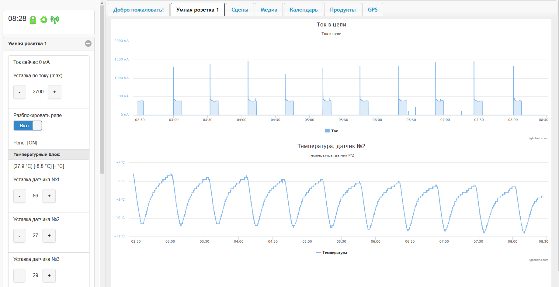
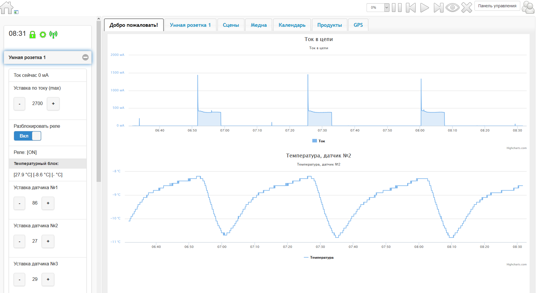
This is a refrigerator, temperature sensor in the freezer. I'm a little surprised that if you set the control knob in the fridge to “2”, you get the readings on the screens above. If you put on "3" then the refrigerator will thresh for 40 minutes instead of 7 and keeps the temperature between -16 / -18 degrees. Not very smooth adjustment as for me. The information is not worth the extra, it was interesting to see.
It is also interesting that the moments of the starting high current are displayed and the discreteness of the temperature sensor (steps) is visible, since for the current an averaging filter is used, I did not expect to see such bursts on the graph at all.
Sketch for ESP-12F
To force ESP to exchange data via MQTT, you only need to use the appropriate library under Arduino. It should be noted that there are still similar libraries.
An example of working with this library on ESP8266
#include <ESP8266WiFi.h> #include <PubSubClient.h> // Update these with values suitable for your network. const char* ssid = "........"; const char* password = "........"; const char* mqtt_server = "broker.mqtt-dashboard.com"; WiFiClient espClient; PubSubClient client(espClient); long lastMsg = 0; char msg[50]; int value = 0; void setup_wifi() { delay(10); // We start by connecting to a WiFi network Serial.println(); Serial.print("Connecting to "); Serial.println(ssid); WiFi.begin(ssid, password); while (WiFi.status() != WL_CONNECTED) { delay(500); Serial.print("."); } randomSeed(micros()); Serial.println(""); Serial.println("WiFi connected"); Serial.println("IP address: "); Serial.println(WiFi.localIP()); } void callback(char* topic, byte* payload, unsigned int length) { Serial.print("Message arrived ["); Serial.print(topic); Serial.print("] "); for (int i = 0; i < length; i++) { Serial.print((char)payload[i]); } Serial.println(); // Switch on the LED if an 1 was received as first character if ((char)payload[0] == '1') { digitalWrite(BUILTIN_LED, LOW); // Turn the LED on (Note that LOW is the voltage level // but actually the LED is on; this is because // it is acive low on the ESP-01) } else { digitalWrite(BUILTIN_LED, HIGH); // Turn the LED off by making the voltage HIGH } } void reconnect() { // Loop until we're reconnected while (!client.connected()) { Serial.print("Attempting MQTT connection..."); // Create a random client ID String clientId = "ESP8266Client-"; clientId += String(random(0xffff), HEX); // Attempt to connect if (client.connect(clientId.c_str())) { Serial.println("connected"); // Once connected, publish an announcement... client.publish("outTopic", "hello world"); // ... and resubscribe client.subscribe("inTopic"); } else { Serial.print("failed, rc="); Serial.print(client.state()); Serial.println(" try again in 5 seconds"); // Wait 5 seconds before retrying delay(5000); } } } void setup() { pinMode(BUILTIN_LED, OUTPUT); // Initialize the BUILTIN_LED pin as an output Serial.begin(115200); setup_wifi(); client.setServer(mqtt_server, 1883); client.setCallback(callback); } void loop() { if (!client.connected()) { reconnect(); } client.loop(); long now = millis(); if (now - lastMsg > 2000) { lastMsg = now; ++value; snprintf (msg, 75, "hello world #%ld", value); Serial.print("Publish message: "); Serial.println(msg); client.publish("outTopic", msg); } }
In short, when you need to transfer data, they are passed to the publish function ("SmartPowerSocket1 / Current", "2"). We transfer the current value equal to the 2nd parrot.
To get data from a broker, you simply need to subscribe to the topic that interests us and check the functions from which the data came up in the kalbek functions, decomposing them using the corresponding variables. That's all.
The final sketch turned out quite voluminous, but it uses absolutely standard approaches to the organization of the exchange on i2c, 1-wire and work with other entities. I think the person who has already dealt with the Arduino will not be hard to understand and modify the control logic to fit your needs, if you need it at all.
Eeprom In the sketch, the storage of parameters in the EEPROM is organized and, in addition, when the MQTT server is available, they are also pulled from there when the device starts.
ArduinoOTA . Even in the sketch, such a thing as ArduinoOTA (OTA - “over the air”, which can be translated as “over the air”) is skipped, that is, the firmware can be uploaded via Wifi.
The link above has a recipe for how to use it. From myself I’ll add that loading in this way is several times faster, but it requires embedding special processing into the sketch. The main loop should not be overloaded otherwise the connection between ESP and ArduinoIDE will not occur. For this purpose, the time of one pass of the main loop is measured in the sketch of so many different timeouts. The more often the ESP checks “do they want to flash me?” The more stable it all works. Another feature that I have not yet overcome, ArduinoOTA refuses to flash in some wifi networks, although everything is pinged. Most likely to succeed if ArduinoIDE and ESP are connected by a dedicated (for IoT only) access point.
Buttons. At first I wanted to make more than two buttons, but it turned out that the GPIO on the ESP-12F was coming to an end. It is good reasoning that almost no one will click on these buttons anyway (if there is control through the webmord of a smart home), it was decided to limit it to two. I tied them to adjust the current setting, and if you press both, an emergency shutdown of the relay occurs immediately. After that, you can turn it on only if you restart the device itself via power or via webmord. Thus, I tried to add a bit of protection against reckless switching on if the current had gone beyond the permissible limit, because this could mean an emergency situation.
[ Sketch as I update will post here. ]
"I do it!"

The mysterious black box began to regularly click the relay and publish, an equally mysterious, quiet high-frequency squeak of different tonality in different modes of operation - a feature / bug resulting from the operation of the power supply, apparently there is a loose musical choke.
It's funny that it was he who indirectly helped me catch the moments of the hang of individual nodes. You can watch with your eyes, but it is tiring, the moment when the rhythm of the sound changes is very easily caught by hearing in the background. Therefore, I did not calm down this throttle and even thought about adding such a function to other devices for debugging.
Some time pondering how to demonstrate the device if it is itself a boring black box and does not even move. Let's try to brew tea using a kettle and one of the temperature sensors, for one we calculate how much energy it will take.
By pressing a button several times that unlocks the relay, nothing happened, it later turned out that the current setting was very low and worked the first few times.
When the boiler warmed up a little, the current fell a little and the relay unlocked.
Having settled down more comfortably, I prepared myself for a long time to expect water to boil, but the Chinese devil-boiler boiled water so quickly that I barely managed to turn it off in manual control mode. And the temperature sensor was not so quick, and although I set the setpoint to 95 degrees, I’m afraid by the time it is triggered everything around would be already in boiling water, I’m afraid that I don’t want so much tea.
At first, I was embarrassed by the inscription on the 500W boiler, but from the current it can be seen that this is true. At the end, I was already afraid that the plastic part of the boiler could melt and spoil
"Experiment", but it cost.
Of course, it would be possible to make a video of the scenario, but it seems to me that the real result is more valuable in experiments, so I showed what happened the first time without rehearsals. In general, here is a comic baptism of a smart outlet.
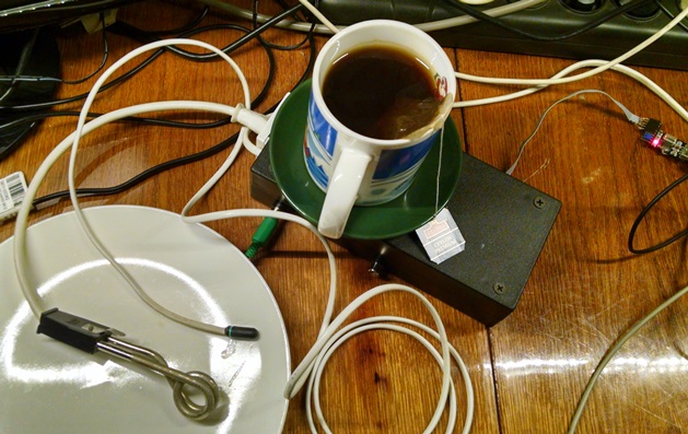
It is very simple to calculate the expended energy based on the fact that the water boils in 2.5 minutes. and all this time, the current was about 2.5A: (2.5A * 220V) / 60min. * 2.5min. = 0.023 kWh
If you have a goal to keep records of electricity, it will be good to add another voltage sensor that can be made from a step-down transformer, this method can also be used to isolate the galvanic and the voltage is not dangerous for measurement using the microcontroller's ADC. And you need to add it because the voltage in our sockets is almost never 220V, but ± 10V is walking at best.
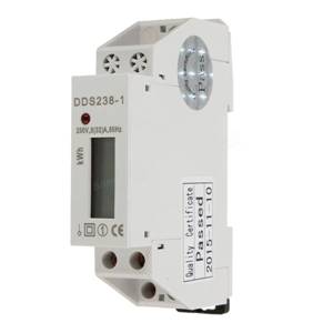
And another option if you don’t need current and voltage readings on their own, but only metering of electricity consumption is needed - these are Chinese single-meter electricity meters , they usually have a pulsed low-voltage output and they are very compact. In this case, their use is fully justified.
PS If you really plan to assemble a real Wifi maker, I strongly recommend counting the thickness of the wires and the power of the relay as the average electric kettle is very voracious.
UPD №1: In comments, several more devices were suggested, including those that were completed:
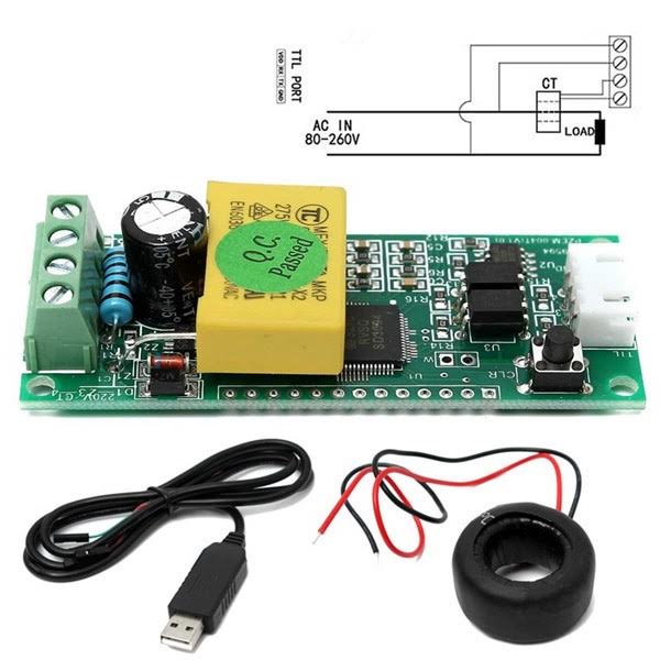
1. Ready module for measuring electrical parameters PZEM-004T .
2. Finished Sonoff Pow modules.
3. Also complete module on esp8266 electrodragon .
All Articles