Note to the astronomer: equatorial mount do-it-yourself
A few years ago, my wife and I went on a scientific holiday. We spent a lot of time driving around the beautiful American Southwest, visited many wonderful natural parks on the Colorado Plateau. After traveling hundreds of kilometers through deserted places under a clear starry sky, I began to dream of an equatorial mount - a platform for a camera that will rotate to compensate for the rotation of the planet. When shooting stars with a tripod, a more or less long exposure will cause the stars to turn into light strokes. This is a curious artistic effect, but it does not allow an astrophotographer to capture the subtle details of the starry sky. Mentally, I was calculating the gear ratios of the gears for mounting, while my wife was sleeping in the next seat. Returning from a trip, I began to pick up tools for the realization of my dreams. I decided to create an equatorial mount from sheet acrylic, and cut the gears with a laser. I took Autodesk Inventor as a software for designing mechanics and creating drawings. References to the drawings:
- GEM Gear Box ans Gears.iam
- Gear Mount with Power Train.dwg
- Final GEM_quarter_inch_rod_final.dwg
- GEM Gear Mounts_Sheet_1.dwg
- GEM Gear Mounts_Sheet_3.dwg
Stage 1. Inspiration


These are my favorite photos from a trip to Monument Valley. The second one is an example of how the Earth’s rotation creates glowing tails in stars, even with a short “long exposure” (30 seconds). Aperture f / 1.8, lens Canon T1i, focal length 50 mm. You can even see the faint glow of the Milky Way.
Be sure to go on nature, away from the city, in unfamiliar places, and spend time watching the starry sky. Inspiration - the most important condition for the implementation of any project.
Stage 2. Tools and materials
I used the following tools and materials (dimensions are in millimeters and initial in inches):
Instruments:
- Arduino SDK
- Autodesk Inventor (or equivalent CAD)
- Laser CNC machine
- Calipers
- Hacksaw
- Screwdriver / screwdriver
- Adjustable wrench
Materials:
- Sheet acrylic plastic 5 mm (3/16 ") or 6 mm (1/4")
- Ball bearings with an inner diameter of 6 mm (1/4 ") - 12 pcs.
- M6 × 80 mm screws (1/4 "× 3")
- Ball bearings with an inner diameter of 12 mm (1/2 ") - 12 pcs.
- Stud M12 mm (1/2 ")
- Hexagon bolts M6 × 90 mm (1/4 "× 3 1/2") - 6 pcs.
- 6 × 25 mm nylon gaskets (1/4 "× 1") - 12 pcs.
- Washers with an internal diameter of 6 mm (1/4 ") - about 20 pcs.
- Washers with an inner diameter of 6 mm (1/4 ") and an outer diameter of 32 mm (1 1/4") - about 15 pcs.
- M6 nuts (1/4 ") - about 30 pcs.
- Stainless steel piano hinges
- Square with adjustable angle arm
- Levels
- Tripod head with pan and tilt
Control and electronics:
- 12 V step motor
- Stepper Motor Controller
- Arduino uno
- 12 volt power supply
- Green laser 5 mW class IIIA (optional)
Stage 3. Calculation of gears
First you need to calculate such gear ratio gears, so that the platform with the camera makes one turn per day. I spent a lot of time thinking through the design. I came to the conclusion that you need to use a motor with a rotational speed of one revolution per minute, and then the gear ratio of the entire gearbox should be 1: 1440 (1 × 60 minutes × 24 hours = 1440). This value is very conveniently factorized. I spread it to factors [3, 4, 4, 5, 6], i.e. the gears will have gear ratios of 3: 1, 4: 1, 4: 1, 5: 1 and 6: 1. You can factor it otherwise. If you take a motor with a different rotation speed, you will have to pick up your gear ratios for it.
Now for CAD. AutoDesk Inventor has a very convenient built-in generator of spur gears. He takes the parameters you entered, calculates the configuration of gears and shows the result. But this tool does not allow virtual gears to be assembled into a virtual gearbox (as of 2012).
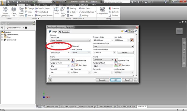
Go to the menu in the Design tab, there will be a section of mechanical components "Power Transmission". One of them is designed for the design of spur gears. Click on it, the “Spur Gears Component Generator” dialog box will open:

Since we are creating a reduction gear and we’ll use the contours of gears for cutting on a laser machine, we can leave the default settings in this window. I only changed the value in “Desired Gear Ratio”. For the first set of gears, enter the value 3 and click “Calculate”:
At the bottom of the dialog box, the values for Gear 1 and Gear 2 will be generated. Make sure that both gears are configured as a component, and when you click “OK” you can save them to a file. After that, they will appear in the work area:

You can move the component as you like. Repeat the process for all selected gears (in my case 3: 1, 4: 1, 4: 1, 5: 1, 6: 1) and place them in the working area.
Now edit the thickness of the gears to match your acrylic plastic. In my case - 5 mm (3/16 ").
Stage 4. Connecting gears
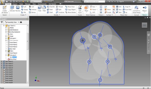
First, in the center of each gear make holes of the desired diameter. Then we tie the axis of rotation of those gears that will be located on the same shafts. Finally, we define the displacement of the planes between groups of gears connected to each other.
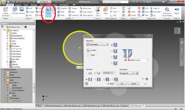
To make holes, open one of the components and create a new contour (sketch) on the gear plane. In the "Draw" section, select "Point" and place the point in the center of the gear. Complete the contour creation and in the “Modify” section, select the “Hole” tool. Select the created point and set the diameter of the circle in accordance with your stud (in my case 6 mm, 1/4 "). The type of hole is simple drilled. Do the same for all the other gears.
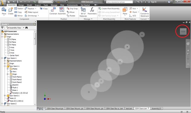
We now turn to the connection of groups of gears by creating and linking their axes of rotation. In the Work Features section, select the Axis tool. Select one of the holes created and create an axis of rotation. Do the same for those gears that need to be connected to the first. Having created a set of axes, in the “Position” section, click on the “Constrain” item. Now bind the two axes by clicking on both and applying “Constrain”. Groups of gears can be connected in any order. I started with the biggest and consistently joined the smaller ones.

When you finish snapping all the axes, you need to position the planes of groups of gears. That is, to spread them in space so that they can rotate freely:

Now we have a set of gears, correctly connected to each other. You can begin to design the gearbox.
Stage 5. Gear Design
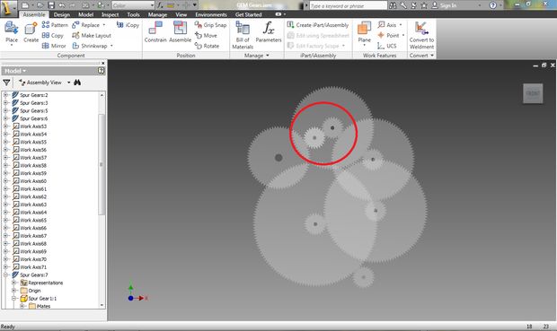
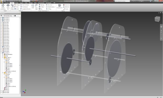
Now you need to create three separate panels in which there will be ball bearings for the shafts. But first, let's select the interposition of gears. Moving them, carefully check that they do not touch the shafts of other gears. I had to add a second set of gears with a gear ratio of 1: 1, so that you can pass the aluminum shaft through the entire gearbox:
When finished with the placement of gears, create a new work plane. This will be the gear housing. You can simply draw a rectangle around all the gears, or you can choose the shape of the plane so that it repeats the general outline of the set. I chose the second option.
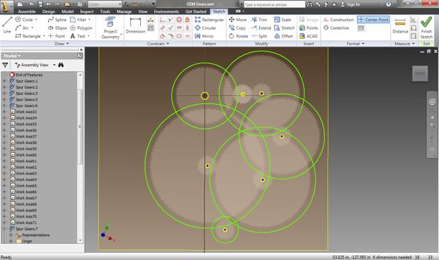
Create a new sketch on the newly created surface. Select "Project Geometry". Click on the holes of all the gears to project their shape onto the work surface:

After projecting the holes, you can create circles whose centers are the centers of projections.
Now connect the circles with straight lines:
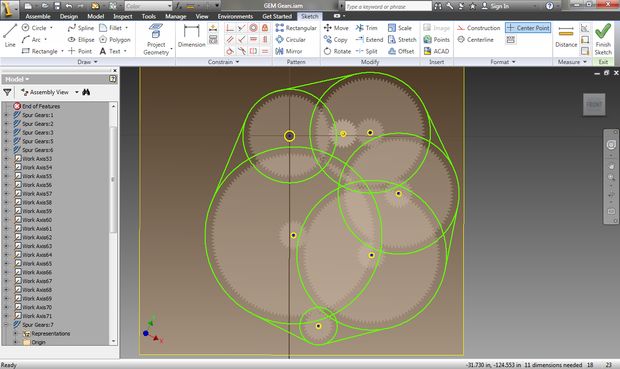
In the Modify section, select the Trim tool and delete all segments inside the resulting outer contour:

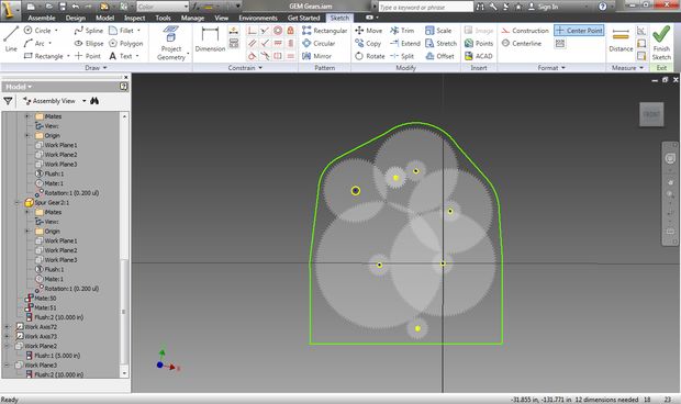
Now create a straightened part at the bottom, to which the piano loop will then be attached, with which we will align the plane of rotation of the mount with the plane of rotation of the Earth. You can also rotate the whole scheme first so that the gearbox looks more harmonious. After that, draw a rectangle that will be inscribed in the extreme points of the crankcase:

Remove the extra lines:
After creating the crankcase contour, you need to modify the projected holes so that they match the outer diameters of your bearings. I used two sizes: 28 mm (1.125 ") and 20 mm (.75"):
Now you need to create a three-dimensional object (extrude) from this outline - the crankcase panel. The thickness should match your plastic (in my case, 5 mm, 3/16 "). Then create two more copies of the panel - these are the front and back sides of the mount.
Stage 6. Power transmission design
Now you need to design the drive pulley and the holes for the installation of a stepper motor. In Autodesk Inventor for this there is a very convenient wizard.
On the Design tab in the Power Transmission section, select Synchronous Belts:
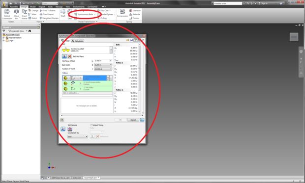
Now create a pulley on the surface of a solid object. To transfer the rotation of the motor to the gearbox, I used the 1: 3 ratio. You will need to select the number of teeth of each gear in accordance with your chosen values:

Now place the power train in the gearbox. Connect the center point of the larger pulley to the shaft of the last gear of the gearbox. Rotate the power train in space so that it fits correctly into the gearbox:
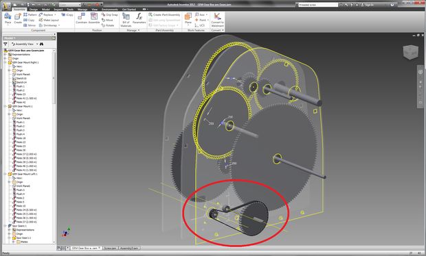
Create holes to install the motor in accordance with the location of the power transmission. The center of the smaller pulley will be the center of the motor shaft:

Stage 7. Laser cut
After completing the design, you need to convert the project files into vector images that your laser CNC machine accepts. First create the first image and delete the perimeter and author information. Adjust the size of the image to the size of your plastic sheet. Paste your gears into the file:

Create another image in the same way and import the gearbox panels.
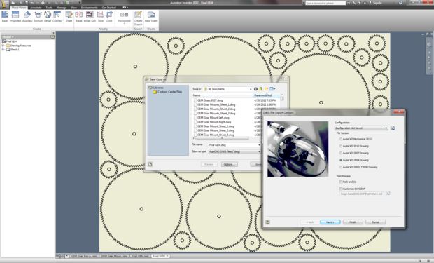
Now we export these images to a format that is compatible with the laser machine software. I created images using Adobe Illustrator and exported to DWG files.
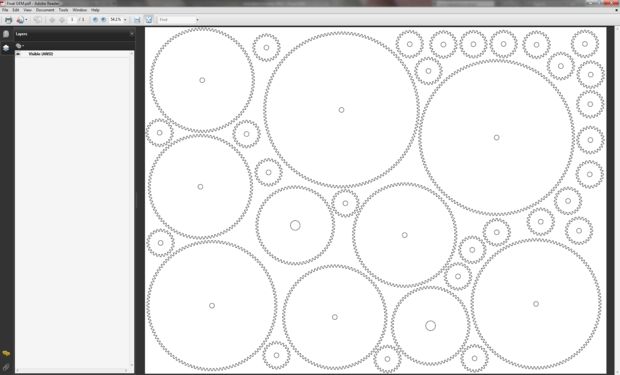
Now open the file in Illustrator.
First select the entire image and specify a line thickness of 0.001 pt or less. The machine I used requires making the lines very thin so that it interprets them as a contour for cutting. If this step is neglected, the machine can regard the vector lines as rasterized images - it simply engraves them on the surface (if you have a machine with laser engraving function). When setting up the machine yourself, do not forget to configure the laser parameters in accordance with the material. Now send files for cutting.
Stage 8. Assembly of the gearbox and power transmission

Inspired by the naive belief that I was close to completion, I began to assemble. In my dreams I made beautiful photos of the sky already this night! The reality was different. The assembly took quite a few hours. It's like a three-dimensional puzzle. I cannot give you specific advice, because the positioning of the elements will depend on the specific screws and washers you use. But I can describe the general approach I have found to solve this puzzle.
As a result, I used the following components:
- M6 screws (1/4 ")
- M6 bolts with square head (1/4 ") for the assembly of three panels
- Hexagon bolts M6 (1/4 ")
- Hexagon bolts M12 (1/2 ")
- Washers with an inner diameter of 6 mm (1/4 ") and an outer diameter of 16 mm (5/8")
- Washers with an inner diameter of 6 mm (1/4 ") and an outer diameter of 32 mm (1 1/4")
- Washers with an inner diameter of 12 mm (1/2 ") and an outer diameter of 38 mm (1 1/2")
- Ball bearings with an inner diameter of 6 mm (1/4 ")
- Ball bearings with an inner diameter of 12 mm (1/2 ")
- M12 stud (1/2 ") (rotating platform for the camera)
- Transition coupling from M12 (1/2 ") to M6 (1/4") (for fastening the tripod head to the stud)
- 6 × 25 mm nylon gaskets (1/4 "× 1") to align the panels relative to each other
Approach the assembly systematically
Engineers have a terrible habit of throwing their heads into the pool without checking the depth. Make a plan for turning a pile of parts into a fully assembled device. I started with the assembly of gears and shafts on the same panel where the power transmission was attached. Then, one by one, he collected the next layers of the gearbox, constantly checking the 3D model.
Be prepared to repeat your actions.
As you assemble, it may be necessary to further adjust the distances between the components. That is, you have to disassemble a part of the structure, add / remove washers. Do not be tempted to immediately tighten each nut and screw; this will only make it difficult to return for adjustment.
Keep order in the layout of components and tools
You need to focus and not be distracted by the search for the necessary parts or tools. As I said, from time to time you will have to disassemble and reassemble. Without a clear understanding of the assembly process, it will be very difficult for you to move forward. And if you have a mess in the workplace, it will not fully focus on the assembly.
Plan your time and place
You will need a lot of time, at least a few hours. Perhaps you won’t manage it all at once, but it’s better not to break up the build process into a large number of sessions, otherwise it will take more time.
Step 9. Programming the motor controller
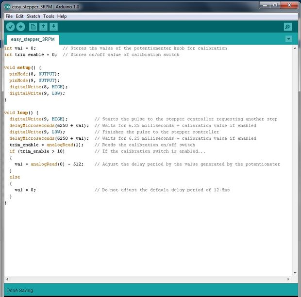
Having finished with a mechanical part of the project, it will be necessary to program and connect Arduino Uno, and also to connect the controller to the motor. Since my power transmission has a 3: 1 ratio, the motor must rotate at a speed of three revolutions per minute for the camera to complete a full revolution in one day.
I also decided to make a calibration pen to fine-tune the rotational speed if necessary. The source code for the Arduino is very simple:
=================================================================== int val = 0; // - int trim_enable = 0; // / void setup() { pinMode(8, OUTPUT); pinMode(9, OUTPUT); digitalWrite(8, HIGH); digitalWrite(9, LOW); } void loop() { digitalWrite(9, HIGH); // delayMicroseconds(6250 + val); // 6,25 + , digitalWrite(9, LOW); // delayMicroseconds(6250 + val); // 6,25 + , trim_enable = analogRead(1); // / if (trim_enable > 10) // ... { val = analogRead(0) - 512; // , } else { val = 0; // 12,5 } } ===================================================================
Stage 10. Electronics

I used an inexpensive stepper motor controller, Easy Driver . To calibrate the motor speed added potentiometer and switch. The voltage is read from the potentiometer slider as analog data and is converted into a numerical value (0-1023) of the calibrating correction. The switch is responsible for whether the amendment will affect the speed of rotation of the motor.
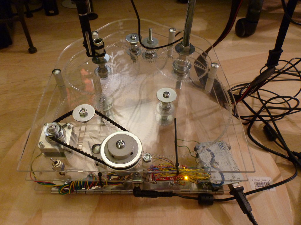
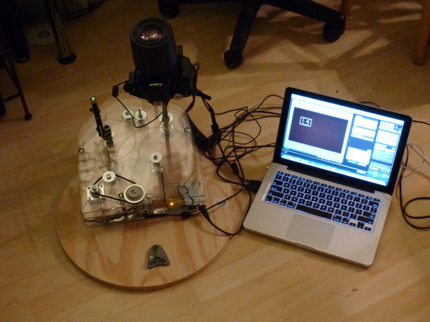
Stage 11. Final product
Now you need to install the mount on a stable stand, it is needed to minimize possible vibrations. I took a round plywood board with a diameter of 50 cm and attached a mount to it using a piano hinge. If the stand is not sufficiently stable, then during long exposures the mount may slightly move, and this will necessarily affect the quality of the photos.
I recommend attaching at least one bubble level to the stand in order to more precisely align the plane of rotation relative to the plane of rotation of the Earth. But if you use the green laser, the levels will not be needed. You can aim the laser at the Polaris and not bother with angle measurements.
To mount the tripod head, I cut about 12 mm from one of the M6 screws. Then the resulting pin was screwed into the adapter sleeve, and a section of pin M12 was screwed into it. Now it was possible to attach the tripod head to the resulting adapter.
As an option, you can fasten the green laser with a coupler to the adapter and screw it onto one of the screws.

Stage 12. Long exposure astrophotography
First, with the help of a green laser, I roughly oriented the mount to the North Star. Then, using the software for his camera, he leveled out more precisely and took two test shots. Shutter speed 60 seconds, ISO 400, Canon 100MM L Macro lens.
Without mount:

With mount:

Stage 13. What's next?
Here are your ideas for further improving the design of the equatorial mount:
- Auto Align Mount with GPS Module for Arduino.
- Control with a stepper motor angle and azimuth for mounting the camera.
- Search finder for heavenly bodies.
- Moon tracker
- More compact design.
- More reliable gear material.
All Articles