Improvement of the intercom with the MQTT protocol for control from the phone (version 2.0)
 Most recently, I already wrote about the completion of the intercom with the MQTT protocol .
In the comments, Vladimir instalator wrote:
The scheme is clearly not thought out. There is no need to intervene at all in the circuit of the tube; it is enough to connect the device to the line break and emulate the tube by tossing the necessary resistances.For some reason, I missed the opportunity to imitate the intercom tube, because such an approach really does not require interfering with the circuit of the tube itself, it will be possible to take control on the approach to it. Moreover, this approach, if necessary, makes it possible not to use a doorphone at all. Hung up the device and open the door from the phone. If you wish, you can completely develop the idea to the battery.
By the way, there was an error in the previous scheme (I corrected the article), which no one paid attention to, and which led to unstable intercom operation. Sometimes he refused to open the door, but I could not understand the reason. I connected the LED between the + and - lines, while the native LED took off the ground when the tube was picked up. Thus, in my version at the time of opening the door, the resistance in the line was not high enough (at least I think so) due to the presence of the LED and the doorphone panel did not understand the opening signal. I understood this only when I began to draw a new scheme with “tossing the necessary resistances”.
The principle of the tube is known, I described it in a previous article. The only thing that I may have missed is that the panel gives a call to one subscriber at one particular point in time and waits for him to make a decision. Just so, without the fact of an incoming call, it is useless to take and give a signal to open the door of the entrance. This is important, but not everyone seems to know about it, as there have been a few comments about this.
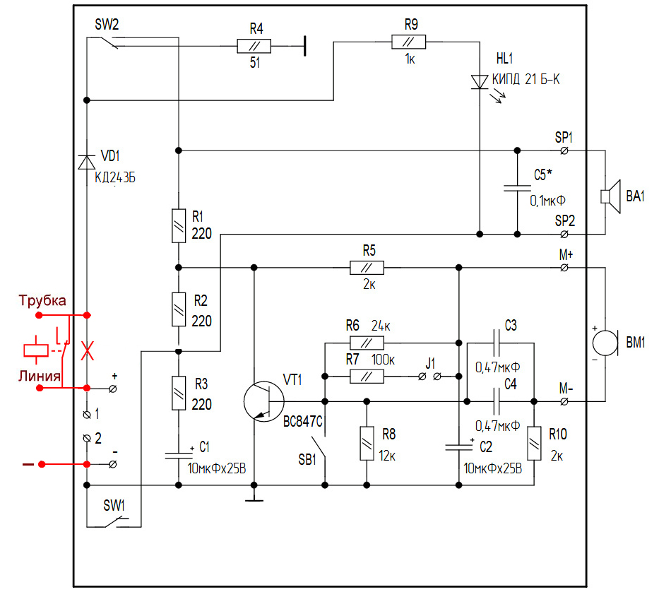
So, let's begin. The access panel distinguishes signals according to the level of resistance in a line; to imitate work, it is only necessary to toss the necessary values to it. I tried to draw a diagram on what I already had in my module: two electromechanical relays and two optocouplers, one of which is deployed to receive a signal.
The implementation looks like this:
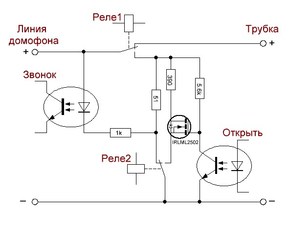
I apologize for such a simple image of the scheme, to make it easier to explain:
- Relay1 is necessary for intercepting control: if we want to intervene in the intercom, we switch the relay, otherwise the handset remains connected and works normally (the same applies to the case when our device is not powered, the relay is closed on the handset).
- Relay2, in normal condition, provides ground for the LED and holds a 51 Ohm resistance in the line to simulate the resistance of a lying tube (unless of course Relay1 is thrown).
- When there is a call, the microcontroller through the optocoupler The bell receives a signal, and a decision is made. In the case of opening, we throw Relay1 and Relay2 in opposite states.
- First, the call panel is waiting for the handset to be removed from the base: it’s up to the Transistor and the Optocoupler Open . By default, the transistor is drawn to the power - open, and in the line imitation of a lifted tube ~ 400 ohms . When a signal is given to the Optocoupler Open , the transistor is attracted to the ground and breaks the circuit, which is equivalent to a signal to open.
For some reason, it didn’t work out purely on the optocoupler: the doorphone panel constantly produced a Lin1 error, which meant a break in the line: either there was not enough current or opening speed.
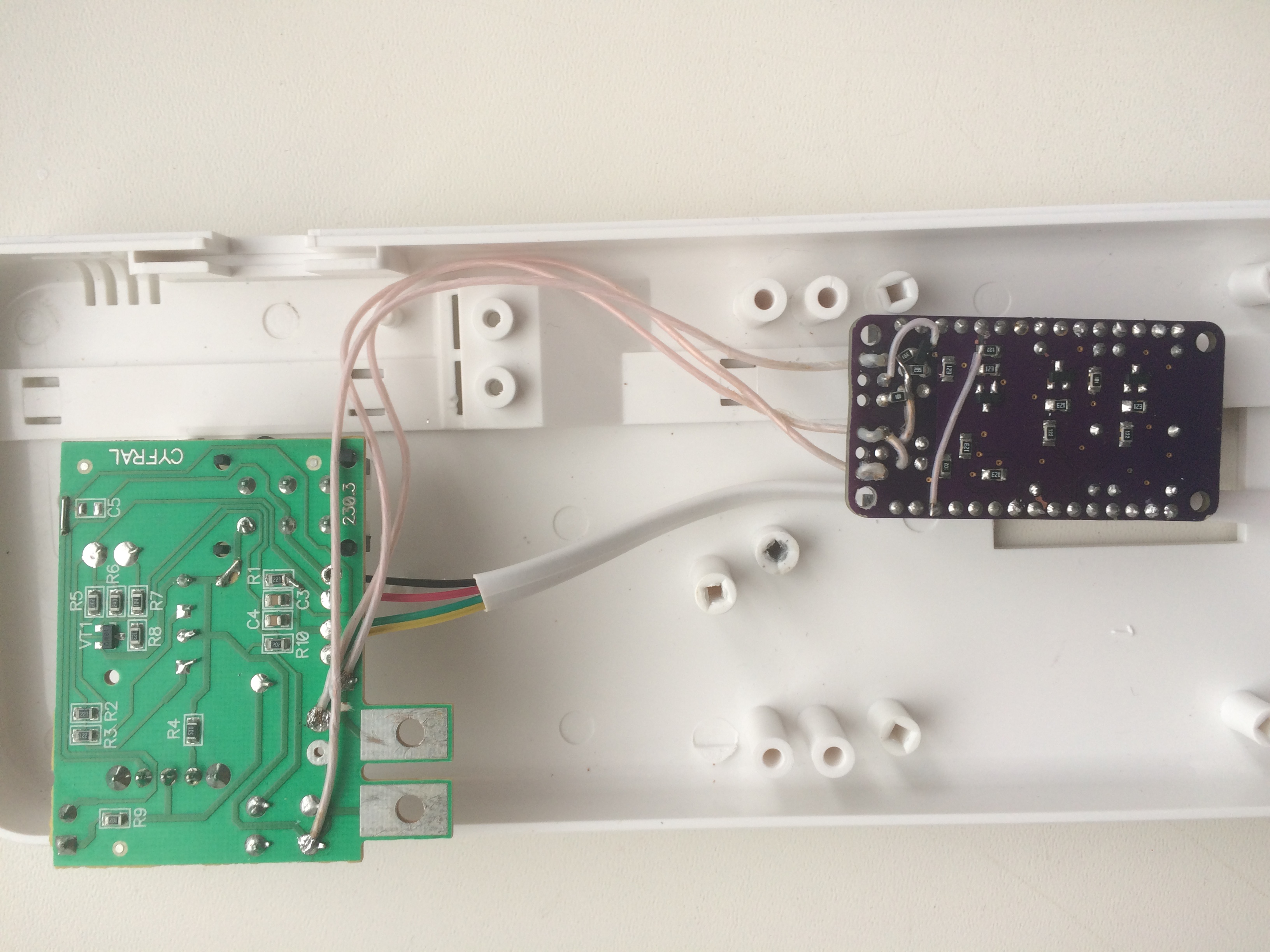
Attached the transistor and resistors mounted mounting:
I repeat, I did on the relay module, which I already had after the first version, with a certain set of relays. Surely the circuit can be optimized, for example on solid-state relays:
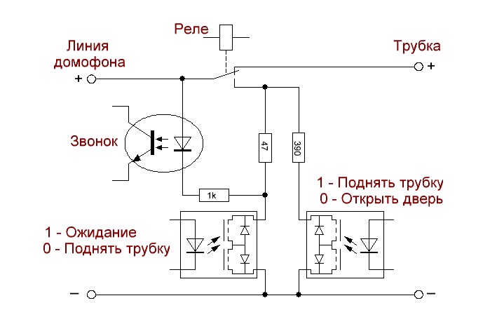
Or something like that depends on your imagination. Only it is necessary to carefully select the solid-state relays, because they have a non-zero channel resistance and can have a significant impact at the time when the line should be 50 Ohms. A solid-state relay channel usually has a resistance of 5 to 25 ohms, which will significantly affect the background of the required 50 ohms.
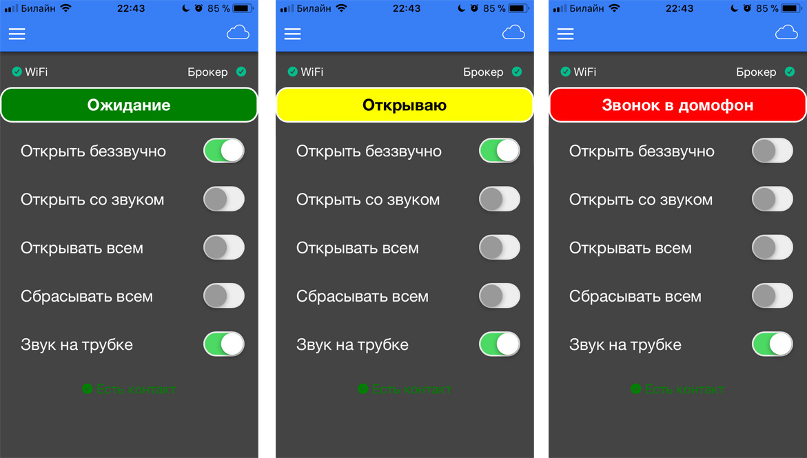
The program has undergone very small changes in the elimination of deficiencies and the addition of the Open mode silently . In practice, most of the time I used the combination Turn off the sound and Open one-time , I decided to merge the two settings into one: the call is intercepted in silent mode, opens the door and goes back to the sound mode.
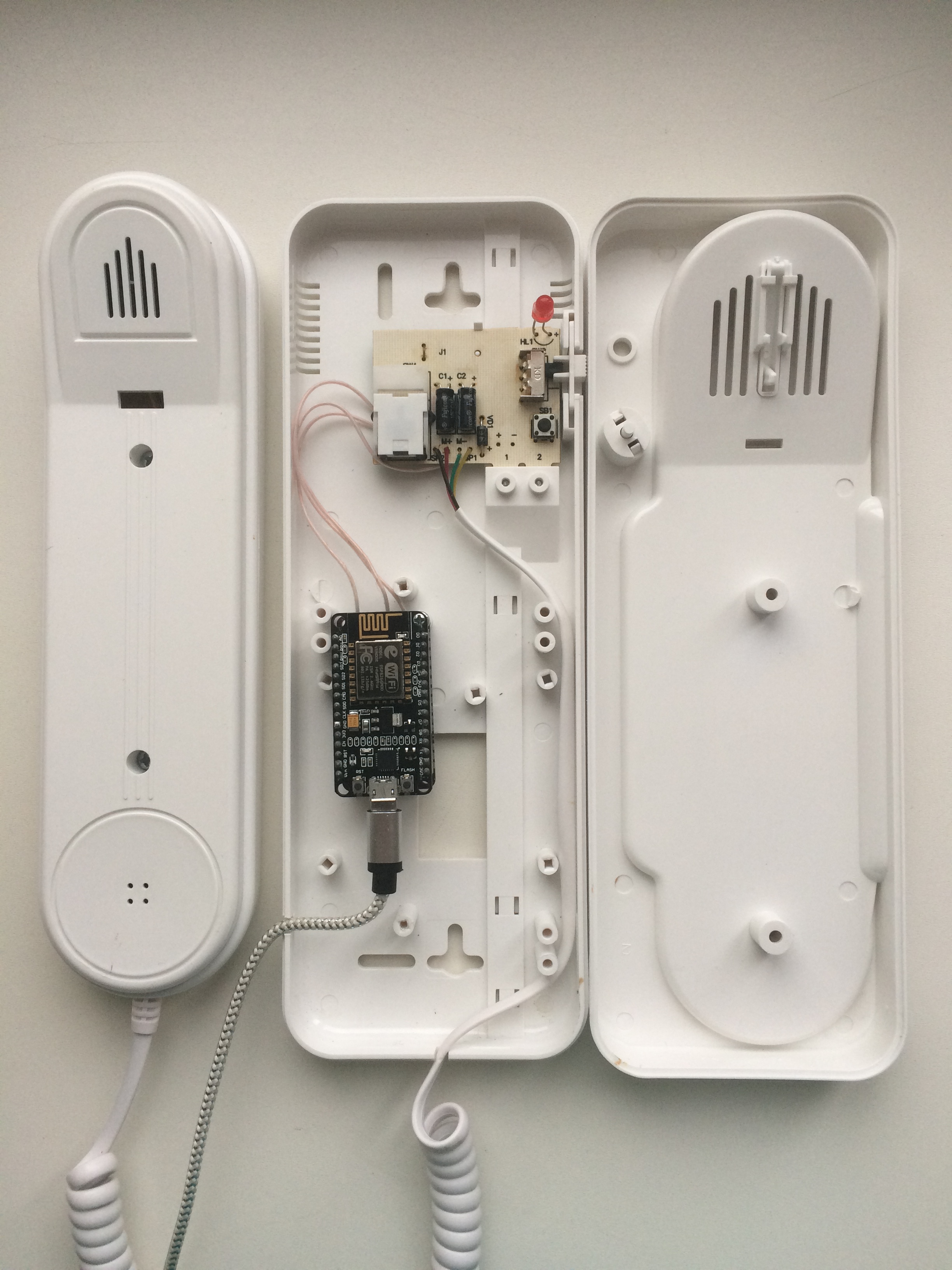
I placed the payment in the same way inside the doorphone tube, soldering to the main board, the benefit now is just three wires. I did this to hide the device inside and use standard line clamps.
But now it is not necessary, you can hang the device in the line break.
Those interested can try (maybe I'll try it myself later) to remake the device into battery power. To do this, you will have to slightly change the scheme and logic of operation: the call to the intercom will wake up the microcontroller, it will in turn connect to wi-fi and check if there are commands for it to open. If not, set the call status and wait for the decision, then go to sleep again. Energy costs do not have to be large, the intercom doesn’t ring as often, the main thing is to make the power supply correctly. In the case of battery power, no galvanic isolation is needed, all logic can be done on conventional transistors. The idea seems interesting to me, because not everyone has the opportunity to bring power to the intercom. Maybe there is a wish to help with the body and the mobile application? You can try to gash in the series.
In general, I am very pleased with the resulting crafts, also stitching through the air is a pleasure. I invite you to discuss.
All Articles