Brief introduction to stm32 microcontroller application development
People quite often ask me to help them get started with stm32 microcontrollers. Answering their questions and helping them with projects, I realized that it would be better to write an article that would be useful for everyone to start programming stm32 microcontrollers. Despite all its numerous capabilities, stm32 controllers have a rather high threshold of entry, which for many remains inaccessible. In this article, I will try to give the reader a detailed guide on how to create projects on stm32 and how to organize your program.
Using the stm32f103c8t6 microcontroller as an example and the Blue pill module, we consider the structure of a typical project for the IAR development environment and create a working firmware.
Anyone who is interested to start working with stm32, welcome under cat.
All the examples that follow will be made in the IAR Embedded workbench for ARM v7.30. The environment is installed on Windows XP, which is installed in the VirtualBOX virtual machine launched from Mac OS X El captain. It also uses the ST-LINK programmer, which connects to the Blue pill board purchased on AliExpress for ~ 120K.
To create a model project will require:
The attached project template was not taken entirely from somewhere on the Internet, but was created by hand from the examples that came in PeripheralLibrary, the files from the CMSIS package, and its own customizations. The project template does not contain files that belong to any development environment and can be used for any of them (I did not check, but I suppose so).
A detailed description of the directory structure may seem too complicated for beginners, however, it will also be useful to study it.
To create our first project, you first need to create a folder for it. Let's call it EX01.
Run the IAR and in the Project menu select the item Create New Project .
The toolchain value should be left ARM, and the Project template we choose C → main. Next, click OK.
A save project window will appear. In it, select the previously created folder. Let's call the project ex01. Now, you can click Save .
As a result, an empty main file and an empty project will be created, which does not contain any settings yet. The next step will be to save the Workspace workspace so that it does not interfere with our questions in the future. Click File → Save Workspace . We call it ex01 and click Save .
Now we are ready to use the project template. Copy it from the archive to our folder EX01.
The main files that created the project template should be replaced with files from the project.
After we have copied the project template, you should configure the project itself.
To do this, select the menu Project → Options . A window will open that will contain a list of categories of options on the left, each of which will have certain bookmarks.
Select the General Options category and the Target tab in it. In the Processor Variant group, select the Device option and click next to it to select a specific device. In our case, it will be ST → STM32F103 → ST STM32F103x8.
The next category that requires our attention is the C / C ++ Compiler category and the Preprocessor tab.
Block Additional include directories should be filled with links to the directories of the project template.
PreInclude file, you must select the PerLib library configuration file, and the Defined symbols should specify STM32F10X_MD so that the initial initialization files will set the correct core clock and correctly configure the PLL.
Since we are using ST-Link v2 as a programmer, you should select the driver that the development environment will use. We select the Debug category and the Setup tab, on which we will select Driver ST-Link in the drop-down list.
Now you need to configure the firmware fill in the controller. This can be done in the same category, on the Download tab. We are interested in the Verify download and Use flash loader (s) options.
Since we chose ST-Link as a means of uploading the firmware to the controller and debugging, we need to configure its driver so that it works with our controller. The Blue Pill does not have a full-featured JTAG connector that can work using the full JTAG protocol. Instead, we will use its simplified mode called SWD. This JTAG mode uses only three lines. These are GND, SWDCLK and SWDIO. By default, the full JTAG mode is enabled, so we need to change it to SWD and set the core frequency to 72 MHz.
In the list of categories, select ST-LINK and change the option in the Interface group to SWD.
Now you can click OK , our project is configured.
Now it remains to do the last, but very important action, before there, how we will begin to compile our first program. You need to add files from the template to the project.
Files are added to the project in the Workspace panel. There is already a main file, but we need to add PerLib, as well as one of the initial initialization files from the startup directory and initial initialization files from the system directory. We could simply throw in a bunch, but then we would have to suffer, and if the project grows too large, then such a dump would be very disturbing.
The IAR development environment allows you to create groups of files. Groups are purely a virtual concept. They only allow you to organize files in the project. No relation to the disk directories of the group do not have.
We will create groups for each directory from the project template and place the template files there.
First, create the config group and put the stm32f10x_conf.h file into it from the config directory.
To do this, right-click on the project name in the Workspace window and select Add → Add Group in the drop-down menu. Let's call the group Config.
To add files to this group, right-click on it and select Add → Add Files. In the window that opens, open the config folder and select the stm32f10x_conf.h file.
Similarly, add the contents of the Perlib, Startup and System folders. You do not need to add the Core folder, there are only header files that are available from the added Perlib library.
Now the project is fully ready for further development.
Many novice programmers are accustomed to the fact that a program consists of one cycle in which functions are called one after another. The next function is called only after the previous one has completely completed its work. This paradigm offers Arduino or various articles with lessons for beginners. However, large projects are rarely single-threaded. As a rule, more or less serious firmware can have several threads.
In microcontrollers, for the organization of multithreading, Real Time Operating Systems (RTOS) are used, such as ThreadX or FreeRTOS. All of them allow you to create many such cycles, in which functions are executed one after another, only cycles work simultaneously. Like several Arduins, rammed into one microcontroller.
With all its power, the RTOS introduce certain difficulties. For example, each thread has its own stack, its own memory area. If several threads need to access the same memory cell, they should synchronize their actions using mutexes or semaphores. Incorrect use of synchronization objects can lead to deadlocks or inversion of thread priorities. In addition, processing interrupts from the periphery also requires special attention in a multi-threaded environment, since the problem arises of saving the stack and choosing the conditions under which the interrupt call does not destroy the stack of the interrupted thread. And the interrupt handler itself must also work to the end.
OSVR allocates a tiny interval of time for each stream. After this interval, the RTOS switches to the next flow (no matter if the previous one managed to complete its actions or not) and so on in a circle. Different threads may receive different time intervals, depending on their priority. Such multithreading is called “displacing”.
The component of the RTOS, which is called the "scheduler", is responsible for iterating over the flows and transferring control to them for a short time interval.
It is difficult for novice programmers to immediately master the huge and complex stm32 peripherals and, at the same time, also learn RTOS.
Fortunately, there are ways to do multi-threaded applications without RTOS. For this, “cooperative multithreading” comes to our aid. Cooperative multithreading allows you to do relatively small multithreaded projects without attracting RTOS.
What is the essence of cooperative multithreading? With such multithreading, each thread takes as much CPU time as it needs, but not enough to fulfill its entire task at once. This places very stringent requirements on the style of writing cooperative multi-threaded applications.
Cooperative multithreading has several advantages and disadvantages. The choice of the multithreading paradigm depends entirely on the developer and the requirements of the task performed by him.
The main advantages of cooperative multithreading are the lack of a scheduler, a single stack for all threads, no need to synchronize threads, and ease of handling interrupts from the periphery.
Unfortunately, there are drawbacks. In particular, the hang of one of the threads will lead to the hang of the program as a whole. Also, incorrect spelling of one or more threads can lead to a delay in the execution of the rest. And this is not a complete list.
The basis of writing cooperative multi-threaded applications is the state machine. I will not describe it in detail, because here it is already described in detail. However, I will briefly explain the essence. The state machine is an abstract object, the number of states of which is finite. The object moves from one state to another, either under the influence of external factors or due to internal processes. In our case, the flow of a cooperative application is an implementation of a state machine.
A thread has a list of states. In each state, either some short action is performed, or nothing. Switching states can be done either by calling external functions, or when conditions arise in which the flow in the current state is no longer possible and switching to another state is required.
For several years of working with stm32 microcontrollers, I have developed some structure of a cooperative multi-threaded application, which I want to present to you.
Each stream is a separate module (header file and code file).
The module has public functions, the prototypes of which are registered in the header file and private ones, which cannot be called from the outside. Each module has at least two public functions:
The XXX_Init () function is called before the main loop in the main () function, and the XXX_Control () function is called in the main loop of the main function.
The XXX module file might look like this:
xxx.c
In order not to be too abstract, let's imagine a real task. Suppose we have a stream that blinks with an LED (twice per second) that is cathode-connected to port PC13. We also have a stream that receives commands through the serial port. If the '0' (0x30) character arrives, then the blinking stops and the '-' sign is sent to the client. If the character '1' (0x31) arrives, the blinking is turned on and the character '*' is returned to the client. When you press any other key, the character 'E' is returned.
The LED flashing control flow will be located in the modLed.h and modLed.c files. This thread is initially in the idle state and does nothing. However, its public function MODLED_command, when receiving an argument, modled_on switches the stream state to
modled_st_on. In this state, the thread lights the LED, remembers the initial value of the global_count counter and goes into the idle state modled_st_wait1. In this state, it constantly checks the current value of the global_count counter, and when the difference between the current account and the initial account is MODLED_BLINK_DELAY_ON, the stream goes to the modled_st_off state. In this state, the thread turns off the LED, remembers the current value of the account and goes into the modled_st_wait2 state. In this state, the thread also compares the current value of the global_count counter with the initial one and when the difference is MODLED_BLINK_DELAY_OFF goes to the modled_st_on state. And this will continue until someone calls the MODLED_command function with the modled_off argument. Then, the function will switch the state of the stream to modled_st_clamp. The thread turns off the LED and goes into the modled_st_idle state.
Initialization of the modled stream begins in the function main by calling the function MODLED_init (). This function initializes the GPIOC port and sets the initial state of the stream. After that, in the loop, the MODLED_control () function is constantly called, which in one iteration checks the current state and performs small actions for it.
The serial control flow is identical.
It has private functions for initializing the GPIO port and the USART1 module. Also, inside it is hidden the interrupt handler from the peripheral module USART1, in which the current received byte is memorized and the stream status is set to moduart_st_command.
Initially, the moduart stream is in the moduart_st_idle state, in which it is waiting to receive a byte. As soon as a byte is received and stored in a variable, the interrupt handler changes the state of the stream to moduart_st_command and the stream checks the received byte. If the received byte is a '0' command, then the MODLED_command function is called with the modled_off argument and the '-' character is returned. If the received byte is a '1' command, then the MODLED_command function is called with the modled_on argument and the '*' character is returned. In other cases, simply return the character 'E'.
The MODUART thread is also initialized in the main file by calling the MODUART_init () function. This function initializes the port and the USART1 peripheral module and puts the stream on standby. In the main loop, the control function of the MODUART_control () stream is called, which checks the current state and executes a small piece of code related to its processing.
The whole secret of cooperative multi-threaded applications is to make small code fragments for each state.
Variable global_count
Probably worth mentioning separately about this variable global_count.
The startup \ startup_stm32f10x_md.s initialization file contains the microcontroller interrupt table. It contains the addresses of handlers for all interrupt peripherals
and cores. However, peripheral interrupts come only when the periphery is initialized. Therefore, initially, handlers point to temporary stubs. But the Cortex M3 kernel interrupt handlers really exist and are contained in the file system \ stm32f10x_it . One of these interrupts is the SysTick system timer interrupt. This timer is used by the RTOS to invoke the task scheduler. But, I use it to call the TimingDelay_Decrement function, which is actually defined in the main file.
At the beginning of the main function is setting the frequency SysTick timer to 1 ms. Consequently,
every thousandth of a second in the SysTick interrupt handler will increment the counter.
It is enough just to remember the values of this counter and their difference will give the time interval between checks in milliseconds. Thus, a single counter can be used for holding time intervals in any number of threads without calling the blocking Delay.
It is possible that there are simpler solutions for connecting PeripheralLib and initial tact initialization files. For example, options in the project settings of other development environments or constants that make the development environment automatically load them when compiling. However, this method, which I cited here as an example, is in itself quite visual and allows, if necessary, to quickly change the initialization parameters of the microcontroller. For example, remake clocking from an internal generator.
Compared with other similar "flashing lights of LEDs on stm32", which are found on the Internet, my turned out to be rather cumbersome. However, on such a template, I start new and complex projects and it does not seem to me such a terrible loss to spend 2-5 minutes to create it.
The complete project can be downloaded from here .
Using the stm32f103c8t6 microcontroller as an example and the Blue pill module, we consider the structure of a typical project for the IAR development environment and create a working firmware.
Anyone who is interested to start working with stm32, welcome under cat.
What we need for further work
All the examples that follow will be made in the IAR Embedded workbench for ARM v7.30. The environment is installed on Windows XP, which is installed in the VirtualBOX virtual machine launched from Mac OS X El captain. It also uses the ST-LINK programmer, which connects to the Blue pill board purchased on AliExpress for ~ 120K.
To create a model project will require:
- Blue Pill module or similar
Easily located on AliExpress on request "stm32f103c8t6 board" and cost about 100₽.

- ST-Link programmer
It is also easily available on AliExpress at the request of "stlink v2" and also costs about $ 100.

There is its more complete version, which is designed to connect the standard ribbon connector IDC20

- IAR 7.30 or newer development environment
The limited version 8.10 can be downloaded from the official site.
- The project template, which contains all the necessary components
The template can be downloaded here.
- STDPeripheralLibrary3.5.0 Feature Reference
The project includes a library of functions StdPeriph3.5.0. A little bit old for serious projects, but for beginners it is quite simple and allows you to avoid headaches when working with the microcontroller's periphery. Handbook in WinHelp (CHM) format can be downloaded
From here
- RM0008 Reference manual
Handbook of microcontrollers family stm32f103c8. The reference book contains a description of the core and periphery of the microcontroller, its architecture, register descriptions. The reference book is desirable, over time, to read along and across and know how each peripheral component works. If you are a supporter of naked CMSIS, then without this PDF you can’t. If a newbie who uses Perlib, then you still need to read how this or that peripheral module works. You can download the directory from the site STMicroelectonics
Project template
The attached project template was not taken entirely from somewhere on the Internet, but was created by hand from the examples that came in PeripheralLibrary, the files from the CMSIS package, and its own customizations. The project template does not contain files that belong to any development environment and can be used for any of them (I did not check, but I suppose so).
A detailed description of the directory structure may seem too complicated for beginners, however, it will also be useful to study it.
Project directory structure
- config
stm32f10x_conf.h
This file belongs to the StdPeripheral package and contains inclusions of header files used in the microcontroller peripheral design. It is assumed that the programmer will comment out unused files himself, depending on the project. By default, all files are included.
- core
This directory contains CMSIS files that are specific to the ARM CortexM3 processor core.
- perlib
This directory contains the header files and source code for the Perlib library in the inc and src directories.
- startup
Here are the files with the primary initialization code of the controller, which install the ARM kernel interrupt handlers and call the kernel clock system initialization functions and the PLL initialization. For each type of microcontroller its own file.
The code in this file is executed BEFORE the main () function of your program is called.
ARM core interrupt handlers, as well as the initialization functions of clocking are not stored in these files, they are only called. And they are stored in the system directory files, which will be discussed later.
For example, in order for the stm32f103c8t6 microcontroller to work at 72 MHz, and not at the default 8 MHz, you need to include the startup_stm32f10x_md.s file in the project.
- system
This directory contains files that contain all the functions of the initial system initialization, ARM core interrupt handlers, as well as descriptions of the names and fields of the microcontroller registers.
stm32f10x.h
This is a file from the CMSIS package that contains addresses, names of registers and their fields for the periphery of the microcontroller. Each peripheral module here is represented as a structure, the fields of which are registers. It also defines the constants and bit masks of the register fields.
stm32f10x_it
Here are the ARM kernel interrupt handlers. With the exception of the SysTick handler, which I used to calculate the time intervals, these interrupt handlers are empty. If, suddenly, in your project you need to handle kernel interrupts, then this file is just for you.
Do not confuse processor core interrupt handling and peripheral interrupt handling. Peripherals such as a timer or USART should be interrupted in your own project files, which you write and add to the project's root directory.
system_stm32f10x
These two files contain the very functions of the kernel clock and PLL initialization subsystem, which are called from the initial initialization file in the startup directory. Namely, the SystemInit and SystemCoreClockUpdate functions.
Create a project
To create our first project, you first need to create a folder for it. Let's call it EX01.
Run the IAR and in the Project menu select the item Create New Project .
Figure 1. Creating a new project 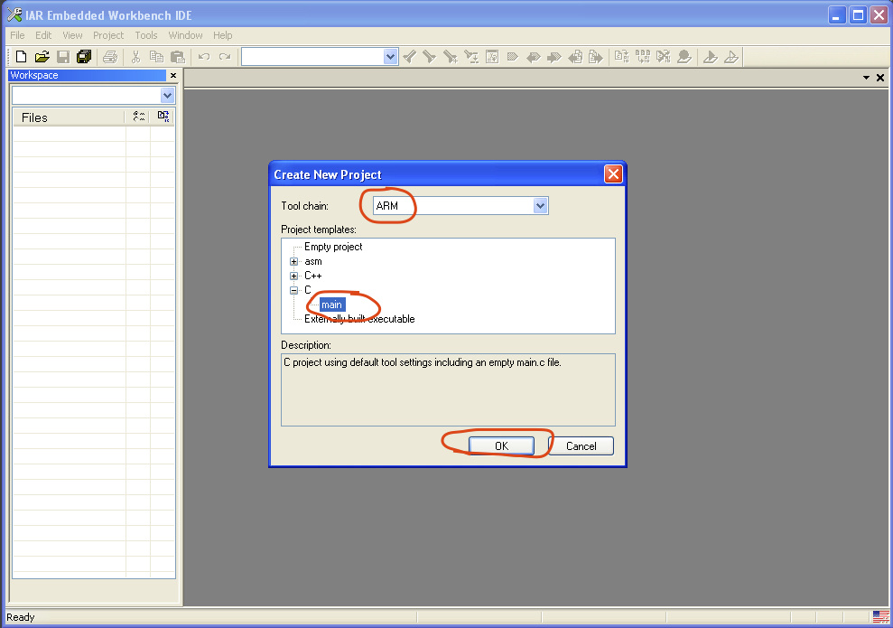
The toolchain value should be left ARM, and the Project template we choose C → main. Next, click OK.
Figure 2. Saving an empty project 
A save project window will appear. In it, select the previously created folder. Let's call the project ex01. Now, you can click Save .
As a result, an empty main file and an empty project will be created, which does not contain any settings yet. The next step will be to save the Workspace workspace so that it does not interfere with our questions in the future. Click File → Save Workspace . We call it ex01 and click Save .
Figure 3. Saving the workspace 
Now we are ready to use the project template. Copy it from the archive to our folder EX01.
Figure 4. Copying files from a template to a new project 
The main files that created the project template should be replaced with files from the project.
After we have copied the project template, you should configure the project itself.
To do this, select the menu Project → Options . A window will open that will contain a list of categories of options on the left, each of which will have certain bookmarks.
Select the General Options category and the Target tab in it. In the Processor Variant group, select the Device option and click next to it to select a specific device. In our case, it will be ST → STM32F103 → ST STM32F103x8.
Figure 5. Select target device for project 
The next category that requires our attention is the C / C ++ Compiler category and the Preprocessor tab.
Figure 6. Preprocessor tab settings 
Block Additional include directories should be filled with links to the directories of the project template.
PreInclude file, you must select the PerLib library configuration file, and the Defined symbols should specify STM32F10X_MD so that the initial initialization files will set the correct core clock and correctly configure the PLL.
Since we are using ST-Link v2 as a programmer, you should select the driver that the development environment will use. We select the Debug category and the Setup tab, on which we will select Driver ST-Link in the drop-down list.
Figure 7. Choosing a debugging tool 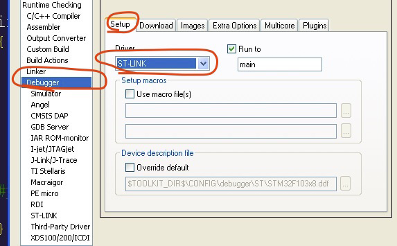
Now you need to configure the firmware fill in the controller. This can be done in the same category, on the Download tab. We are interested in the Verify download and Use flash loader (s) options.
Figure 8. Setting the parameters for flashing the firmware to the microcontroller 
Since we chose ST-Link as a means of uploading the firmware to the controller and debugging, we need to configure its driver so that it works with our controller. The Blue Pill does not have a full-featured JTAG connector that can work using the full JTAG protocol. Instead, we will use its simplified mode called SWD. This JTAG mode uses only three lines. These are GND, SWDCLK and SWDIO. By default, the full JTAG mode is enabled, so we need to change it to SWD and set the core frequency to 72 MHz.
In the list of categories, select ST-LINK and change the option in the Interface group to SWD.
Now you can click OK , our project is configured.
Figure 9. Configuring the ST-LINK driver 
Now it remains to do the last, but very important action, before there, how we will begin to compile our first program. You need to add files from the template to the project.
Files are added to the project in the Workspace panel. There is already a main file, but we need to add PerLib, as well as one of the initial initialization files from the startup directory and initial initialization files from the system directory. We could simply throw in a bunch, but then we would have to suffer, and if the project grows too large, then such a dump would be very disturbing.
The IAR development environment allows you to create groups of files. Groups are purely a virtual concept. They only allow you to organize files in the project. No relation to the disk directories of the group do not have.
We will create groups for each directory from the project template and place the template files there.
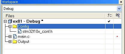
First, create the config group and put the stm32f10x_conf.h file into it from the config directory.
To do this, right-click on the project name in the Workspace window and select Add → Add Group in the drop-down menu. Let's call the group Config.
To add files to this group, right-click on it and select Add → Add Files. In the window that opens, open the config folder and select the stm32f10x_conf.h file.
Similarly, add the contents of the Perlib, Startup and System folders. You do not need to add the Core folder, there are only header files that are available from the added Perlib library.
Figure 11. Full view of an empty and fully configured project 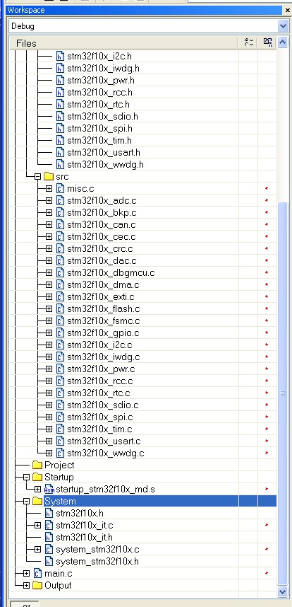
Now the project is fully ready for further development.
Some theory
Many novice programmers are accustomed to the fact that a program consists of one cycle in which functions are called one after another. The next function is called only after the previous one has completely completed its work. This paradigm offers Arduino or various articles with lessons for beginners. However, large projects are rarely single-threaded. As a rule, more or less serious firmware can have several threads.
In microcontrollers, for the organization of multithreading, Real Time Operating Systems (RTOS) are used, such as ThreadX or FreeRTOS. All of them allow you to create many such cycles, in which functions are executed one after another, only cycles work simultaneously. Like several Arduins, rammed into one microcontroller.
With all its power, the RTOS introduce certain difficulties. For example, each thread has its own stack, its own memory area. If several threads need to access the same memory cell, they should synchronize their actions using mutexes or semaphores. Incorrect use of synchronization objects can lead to deadlocks or inversion of thread priorities. In addition, processing interrupts from the periphery also requires special attention in a multi-threaded environment, since the problem arises of saving the stack and choosing the conditions under which the interrupt call does not destroy the stack of the interrupted thread. And the interrupt handler itself must also work to the end.
OSVR allocates a tiny interval of time for each stream. After this interval, the RTOS switches to the next flow (no matter if the previous one managed to complete its actions or not) and so on in a circle. Different threads may receive different time intervals, depending on their priority. Such multithreading is called “displacing”.
The component of the RTOS, which is called the "scheduler", is responsible for iterating over the flows and transferring control to them for a short time interval.
It is difficult for novice programmers to immediately master the huge and complex stm32 peripherals and, at the same time, also learn RTOS.
Fortunately, there are ways to do multi-threaded applications without RTOS. For this, “cooperative multithreading” comes to our aid. Cooperative multithreading allows you to do relatively small multithreaded projects without attracting RTOS.
What is the essence of cooperative multithreading? With such multithreading, each thread takes as much CPU time as it needs, but not enough to fulfill its entire task at once. This places very stringent requirements on the style of writing cooperative multi-threaded applications.
Cooperative multithreading has several advantages and disadvantages. The choice of the multithreading paradigm depends entirely on the developer and the requirements of the task performed by him.
The main advantages of cooperative multithreading are the lack of a scheduler, a single stack for all threads, no need to synchronize threads, and ease of handling interrupts from the periphery.
Unfortunately, there are drawbacks. In particular, the hang of one of the threads will lead to the hang of the program as a whole. Also, incorrect spelling of one or more threads can lead to a delay in the execution of the rest. And this is not a complete list.
The structure of a cooperative multi-threaded application
The basis of writing cooperative multi-threaded applications is the state machine. I will not describe it in detail, because here it is already described in detail. However, I will briefly explain the essence. The state machine is an abstract object, the number of states of which is finite. The object moves from one state to another, either under the influence of external factors or due to internal processes. In our case, the flow of a cooperative application is an implementation of a state machine.
A thread has a list of states. In each state, either some short action is performed, or nothing. Switching states can be done either by calling external functions, or when conditions arise in which the flow in the current state is no longer possible and switching to another state is required.
For several years of working with stm32 microcontrollers, I have developed some structure of a cooperative multi-threaded application, which I want to present to you.
Each stream is a separate module (header file and code file).
The module has public functions, the prototypes of which are registered in the header file and private ones, which cannot be called from the outside. Each module has at least two public functions:
void XXX_Init(); void XXX_Control();
The XXX_Init () function is called before the main loop in the main () function, and the XXX_Control () function is called in the main loop of the main function.
void main() { // XXX XXX_Init(); // YYY YYY_Init(); // ZZZ ZZZ_Init(); while(true){ XXX_Control(); YYY_Control(); ZZZ_Control(); } }
The XXX module file might look like this:
xxx.c
#include "xxx.h" #define XXX_WATER_MAX_THRESHOLD 100500 #define XXX_WATER_MIN_THRESHOLD 9000 typedef enum{ idle, state1, state2, : stateX, }XXX_States; static XXX_States xxxCurrentState = idle; static int xxxToiletWaterLevel=0; //--------- -------- void private_init1() { } void private_init2() { } void private_measureLevel() { } void private_flush() { } void private_superFlush() { } //-------- --------- void XXX_Init() { xxxCurrentState=idle; } void XXX_Reset() { private_superFlush(); xxxCurrentState=idle; } void XXX_Control() { switch(xxxCurrentState) { case idle: private_measureLevel(); if(xxxToiletWaterLevel>XXX_WATER_MIN_THRESHOLD) xxxCurrentState=state1; break; case state1: if(xxxToiletWaterLevel<XXX_WATER_MAX_THRESHOLD) { private_flush(); xxxCurrentState=idle; } else xxxCurrentState=state2; break; case state2: // break; } }
An example of a cooperative multi-threaded application
In order not to be too abstract, let's imagine a real task. Suppose we have a stream that blinks with an LED (twice per second) that is cathode-connected to port PC13. We also have a stream that receives commands through the serial port. If the '0' (0x30) character arrives, then the blinking stops and the '-' sign is sent to the client. If the character '1' (0x31) arrives, the blinking is turned on and the character '*' is returned to the client. When you press any other key, the character 'E' is returned.
The LED flashing control flow will be located in the modLed.h and modLed.c files. This thread is initially in the idle state and does nothing. However, its public function MODLED_command, when receiving an argument, modled_on switches the stream state to
modled_st_on. In this state, the thread lights the LED, remembers the initial value of the global_count counter and goes into the idle state modled_st_wait1. In this state, it constantly checks the current value of the global_count counter, and when the difference between the current account and the initial account is MODLED_BLINK_DELAY_ON, the stream goes to the modled_st_off state. In this state, the thread turns off the LED, remembers the current value of the account and goes into the modled_st_wait2 state. In this state, the thread also compares the current value of the global_count counter with the initial one and when the difference is MODLED_BLINK_DELAY_OFF goes to the modled_st_on state. And this will continue until someone calls the MODLED_command function with the modled_off argument. Then, the function will switch the state of the stream to modled_st_clamp. The thread turns off the LED and goes into the modled_st_idle state.
Initialization of the modled stream begins in the function main by calling the function MODLED_init (). This function initializes the GPIOC port and sets the initial state of the stream. After that, in the loop, the MODLED_control () function is constantly called, which in one iteration checks the current state and performs small actions for it.
The serial control flow is identical.
It has private functions for initializing the GPIO port and the USART1 module. Also, inside it is hidden the interrupt handler from the peripheral module USART1, in which the current received byte is memorized and the stream status is set to moduart_st_command.
Initially, the moduart stream is in the moduart_st_idle state, in which it is waiting to receive a byte. As soon as a byte is received and stored in a variable, the interrupt handler changes the state of the stream to moduart_st_command and the stream checks the received byte. If the received byte is a '0' command, then the MODLED_command function is called with the modled_off argument and the '-' character is returned. If the received byte is a '1' command, then the MODLED_command function is called with the modled_on argument and the '*' character is returned. In other cases, simply return the character 'E'.
The MODUART thread is also initialized in the main file by calling the MODUART_init () function. This function initializes the port and the USART1 peripheral module and puts the stream on standby. In the main loop, the control function of the MODUART_control () stream is called, which checks the current state and executes a small piece of code related to its processing.
The whole secret of cooperative multi-threaded applications is to make small code fragments for each state.
Variable global_count
Probably worth mentioning separately about this variable global_count.
The startup \ startup_stm32f10x_md.s initialization file contains the microcontroller interrupt table. It contains the addresses of handlers for all interrupt peripherals
and cores. However, peripheral interrupts come only when the periphery is initialized. Therefore, initially, handlers point to temporary stubs. But the Cortex M3 kernel interrupt handlers really exist and are contained in the file system \ stm32f10x_it . One of these interrupts is the SysTick system timer interrupt. This timer is used by the RTOS to invoke the task scheduler. But, I use it to call the TimingDelay_Decrement function, which is actually defined in the main file.
//------------------------------------------------------------------- // volatile unsigned long global_count=0; // SysTick, // stm32f10x_it.c void TimingDelay_Decrement(void) { // global_count++; if (TimingDelay != 0x00) { TimingDelay--; } }
At the beginning of the main function is setting the frequency SysTick timer to 1 ms. Consequently,
every thousandth of a second in the SysTick interrupt handler will increment the counter.
It is enough just to remember the values of this counter and their difference will give the time interval between checks in milliseconds. Thus, a single counter can be used for holding time intervals in any number of threads without calling the blocking Delay.
Epilogue
It is possible that there are simpler solutions for connecting PeripheralLib and initial tact initialization files. For example, options in the project settings of other development environments or constants that make the development environment automatically load them when compiling. However, this method, which I cited here as an example, is in itself quite visual and allows, if necessary, to quickly change the initialization parameters of the microcontroller. For example, remake clocking from an internal generator.
Compared with other similar "flashing lights of LEDs on stm32", which are found on the Internet, my turned out to be rather cumbersome. However, on such a template, I start new and complex projects and it does not seem to me such a terrible loss to spend 2-5 minutes to create it.
Source code for modLed.h
File modLed.h
#ifndef __MODLED_H #define __MODLED_H #include "stm32f10x.h" typedef enum{ modled_off, modled_on, }MODLED_Commands; void MODLED_init(); void MODLED_command(MODLED_Commands aCmd); void MODLED_control(); #endif
Source code for modLed.c
File modLed.c
#include "modLed.h" #include "main.h" // #define MODLED_BLINK_DELAY_ON 250 #define MODLED_BLINK_DELAY_OFF 250 // typedef enum{ modled_st_idle, modled_st_on, modled_st_wait1, modled_st_off, modled_st_wait2, modled_st_clamp, }MODLED_States; // , 1 . extern unsigned long global_count; static MODLED_States modledState=modled_st_idle; static uint32_t modledStart, modledEnd; /* PC13 - led (Open drain) */ void modled_init_gpio() { // GPIOC RCC_APB2PeriphClockCmd(RCC_APB2Periph_GPIOC, ENABLE); GPIO_DeInit(GPIOC); GPIO_InitTypeDef gpio; GPIO_StructInit(&gpio); /* Blue Pill , PC13. : PC13 (3 ) . . */ // , . gpio.GPIO_Mode=GPIO_Mode_Out_OD; gpio.GPIO_Speed=GPIO_Speed_2MHz; gpio.GPIO_Pin=GPIO_Pin_13; GPIO_Init(GPIOC, &gpio); // GPIO_WriteBit(GPIOC, GPIO_Pin_13, Bit_SET); } void MODLED_init() { modled_init_gpio(); modledState=modled_st_idle; modledStart=global_count; } // . void MODLED_command(MODLED_Commands aCmd) { switch(aCmd) { case modled_on: modledState=modled_st_on; break; case modled_off: modledState=modled_st_clamp; break; } } void MODLED_control() { switch(modledState) { case modled_st_idle: break; case modled_st_on: // GPIO_WriteBit(GPIOC, GPIO_Pin_13, Bit_RESET); // modledStart=global_count; // modledState=modled_st_wait1; break; case modled_st_wait1: // modledEnd=global_count; // if((modledEnd-modledStart)>=MODLED_BLINK_DELAY_ON) { // modledState=modled_st_off; } break; case modled_st_off: // GPIO_WriteBit(GPIOC, GPIO_Pin_13, Bit_SET); // modledStart=global_count; // modledState=modled_st_wait2; break; case modled_st_wait2: // modledEnd=global_count; // if((modledEnd-modledStart)>=MODLED_BLINK_DELAY_OFF) { // modledState=modled_st_on; } break; case modled_st_clamp: // GPIO_WriteBit(GPIOC, GPIO_Pin_13, Bit_SET); modledState=modled_st_idle; break; default: modledState=modled_st_idle; } }
Source code file modUart.h
File modUart.h
#ifndef __MOD_UART_H #define __MOD_UART_H #include "stm32f10x.h" void MODUART_init(); void MODUART_control(); #endif
Source code file modUart.c
File modUart.c
#include "modUart.h" #include "modLed.h" #define MODUART_BAUDRATE 115200 typedef enum{ moduart_st_idle, moduart_st_command, }MODUART_STATES; static MODUART_STATES moduartState=moduart_st_idle; static uint16_t moduartCmd=0; /* PA9 UART1_TX PA10 UART1_RX */ void moduart_init_gpio() { //RCC_APB2PeriphClockCmd(RCC_APB2Periph_AFIO, ENABLE); // GPIOA RCC_APB2PeriphClockCmd(RCC_APB2Periph_GPIOA, ENABLE); GPIO_InitTypeDef gpio; GPIO_StructInit(&gpio); gpio.GPIO_Mode=GPIO_Mode_AF_PP; gpio.GPIO_Speed=GPIO_Speed_2MHz; gpio.GPIO_Pin=GPIO_Pin_9; GPIO_Init(GPIOA, &gpio); gpio.GPIO_Mode=GPIO_Mode_IN_FLOATING; gpio.GPIO_Pin=GPIO_Pin_10; GPIO_Init(GPIOA, &gpio); } void moduart_init_uart1() { // UART1 RCC_APB2PeriphClockCmd(RCC_APB2Periph_USART1, ENABLE); USART_InitTypeDef uart; USART_StructInit(&uart); uart.USART_BaudRate=MODUART_BAUDRATE; uart.USART_HardwareFlowControl=USART_HardwareFlowControl_None; uart.USART_Mode=USART_Mode_Rx|USART_Mode_Tx; uart.USART_Parity=USART_Parity_No; uart.USART_StopBits=USART_StopBits_1; uart.USART_WordLength=USART_WordLength_8b; USART_Init(USART1, &uart); // // -- USART1 USART_ITConfig(USART1, USART_IT_RXNE, ENABLE); // NVIC_EnableIRQ(USART1_IRQn); // USART1. USART_Cmd(USART1, ENABLE); } // USART1 void USART1_IRQHandler() { // if(USART_GetITStatus(USART1, USART_IT_RXNE)!=RESET) { // USART_ClearITPendingBit(USART1, USART_IT_RXNE); // moduartCmd = USART_ReceiveData(USART1); moduartState = moduart_st_command; } } void moduart_processCmd() { // uint16_t r = 'E'; switch(moduartCmd) { // case '0': { MODLED_command(modled_off); r = '-'; } break; // case '1': { MODLED_command(modled_on); r = '*'; } break; } // USART_SendData(USART1, r); moduartCmd=0; } void MODUART_init() { moduartState=moduart_st_idle; moduart_init_gpio(); moduart_init_uart1(); } void MODUART_control() { switch(moduartState) { case moduart_st_idle: break; case moduart_st_command: moduart_processCmd(); moduartState=moduart_st_idle; break; default: moduartState=moduart_st_idle; } }
Source code file main.c
Main.c file
#include "main.h" #include "modUart.h" #include "modLed.h" // Imported value static __IO uint32_t TimingDelay; RCC_ClocksTypeDef RCC_Clocks; int main() { RCC_GetClocksFreq(&RCC_Clocks); // SysTick SysTick_Config(RCC_Clocks.HCLK_Frequency / 1000); // MODLED_init(); // MODUART_init(); do{ // MODLED_control(); // MODUART_control(); }while(1); #pragma diag_suppress=Pe111 return 0; } //------------------------------------------------------------------- void Delay(__IO uint32_t nCount) { TimingDelay = nCount; while(TimingDelay != 0); } //------------------------------------------------------------------- // volatile unsigned long global_count=0; // SysTick, // stm32f10x_it.c void TimingDelay_Decrement(void) { // global_count++; if (TimingDelay != 0x00) { TimingDelay--; } } //------------------------------------------------------------------- #ifdef USE_FULL_ASSERT void assert_failed(uint8_t *file, uint32_t line) { while(1){} } #endif
The complete project can be downloaded from here .
All Articles