Vector display RIN-609
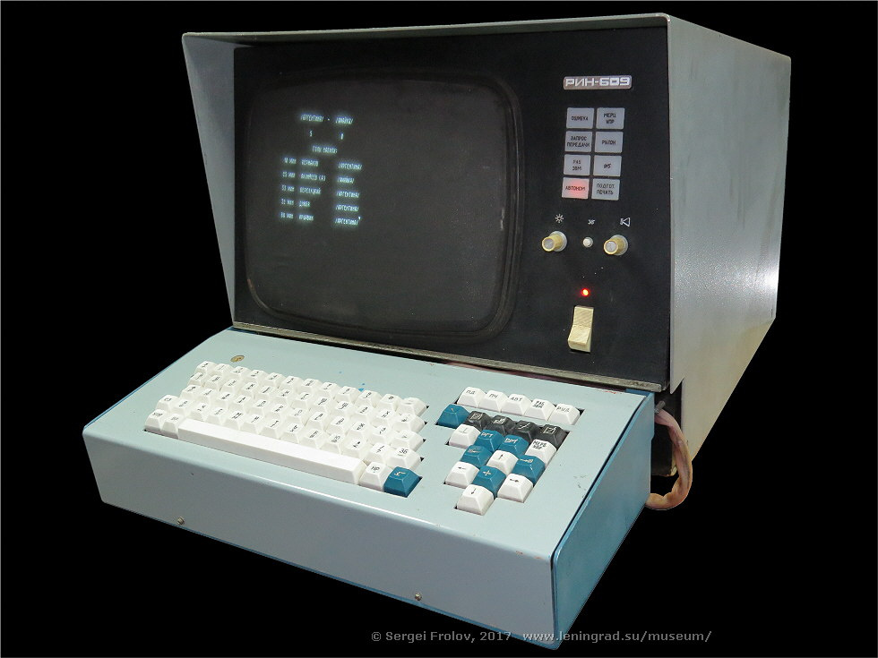
I want to tell you about a new exhibit that I recently had - the vector display RIN-609. After all, this is not an ordinary display, but a vector one. There were very few of them in our country, and it was still impossible to get it. I have two models of calculators with vector display of symbols on a cathode ray tube, and the monitor has appeared for the first time.
This display, or rather, the “tabular sign indicator” RIN-609 was developed in 1977. The mid-seventies is a period when terminals are just beginning to be widely used in our industry. Prior to this, the “electric keyboards” of the Consul type, which are special electric typewriters with a connection to a computer, usually served as a human-computer connection.
In those years, statistics on the convenience of one or another way of displaying characters on the screen was not accumulated, and the developers experimented in this direction. There were no now familiar standards, only in 1975 did the VT-52 appear. Even the word "key" was masculine of the "keys" and reading the documentation in this regard is somewhat unusual (in general, the word "keys" somehow suddenly changed its gender and became female, it will be necessary to delve into information).
If you remember, in a raster CRT monitor the beam displays the image on the screen line by line from top to bottom. And, in principle, he does not care what to display - alphanumeric or graphical information. In RIN-609 applied vector way to display information. In it, the ray draws individually each character, which, unlike the raster method, is encoded not by a matrix of points, but by vectors — first the first character, then the second, and so on until the end of the screen.
Thanks to the existing technical description, you can tell in detail what the monitor is and how the “drawing” of characters occurs.
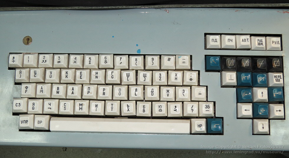
The monitor's keyboard is pretty ordinary. Reed buttons. There are upper and lower case buttons (modern RUS / LAT). The characters under the numeric buttons are “special characters” (C3). They are derived by holding down the "SZ" key and the desired character.
The newline button is to the right of HP. In the top row to the right is a blue arrow button - clear the screen (reset). Next are the cleaning buttons - all characters except service and tab, cleaning to the end of the screen, line, and all information, including service and tabulation.
Tabulation is a special icon that can be placed and erased at each character with the “WGT” buttons. Their meaning is to quickly move the cursor onto them by pressing the blue buttons with arrows ||| <- or -> |||. For tabs in RAM, a whole bit was provided for each character. Tabs used to be an integral part of many typewriters. With their help it is very convenient to print all sorts of tables and statements "in columns". Button "MERZ. UPR. ”Shows in the“ flickering ”mode on the screen service characters like line breaks and others. If the flicker mode is on, then both the service symbols themselves and the corresponding transparency on the monitor flash.
Between the cursor buttons is a special edit button. If you hold it down and press the arrows to the right or left, then the space is inserted (sliding) or the character is erased at the marker.
The topmost buttons switch the operation mode - data transfer, printing, offline mode, working with computers and the "roll" mode. The last mode is a modern SCROLL, when after typing the last line the whole screen shifts up one line and the bottom line becomes empty.
Still there is a lock for the key. He blocks work with computers. It was impossible for an outsider to turn on the display and send something to the computer.
By the way I want to say about the modes of operation.
When the display is turned on, the offline mode is activated. It has no connection with a computer and the user types arbitrary information on the screen. This information can later be poisoned into the computer by switching the display to the computer mode and transmitting the entire frame to it. Or you can immediately transfer it to the computer mode and the display becomes a normal subscriber terminal (the user prints the character that is sent to the computer, and the computer then sends the character that is displayed on the monitor).
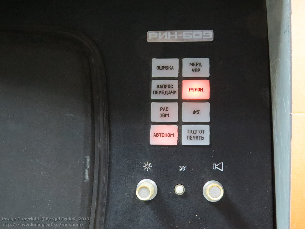
To the right of the screen are banners that are lit depending on the mode of operation. Plus there is a contrast control and speaker volume.
Although the display itself was developed in 1977, this particular copy was released in 1988. That is, the plant produced this model for eleven years. In general, the display remained the same, but changes were made to it. Very interesting to read the documentation. During the USSR, the documentation was very strict. The flywheel of the production cycle was very large, it was very difficult to change something in it. This concerned both documentation and products in general. It was very difficult to replace the documentation with one another. Changes have been made to the current. At the end of the document, a special “change registration sheet” was placed, where all changes were indicated - corrections, deletions or insertions of pages. Judging by this sheet, changes were made constantly and throughout the entire issue - from 1977 to 1988.

Here you can see how the number of pages changed during the release of the product.
The very first thing (judging by this list of registration changes) from the display in 1978 withdrew the possibility of printing. Initially, he could display something on a printing device. But this opportunity was removed. But because of such trifles, the keyboard and the indicator did not change. So they released all the time unused banners and buttons with inscriptions related to printing. Still there is a banner "FL". What he does - did not understand. It can be seen very well seized.

This is insides. In principle, the layout is logical: cathode ray tube, power supply and logic board.

The connectors and the number of fuses are impressive. Blue electrical tape.
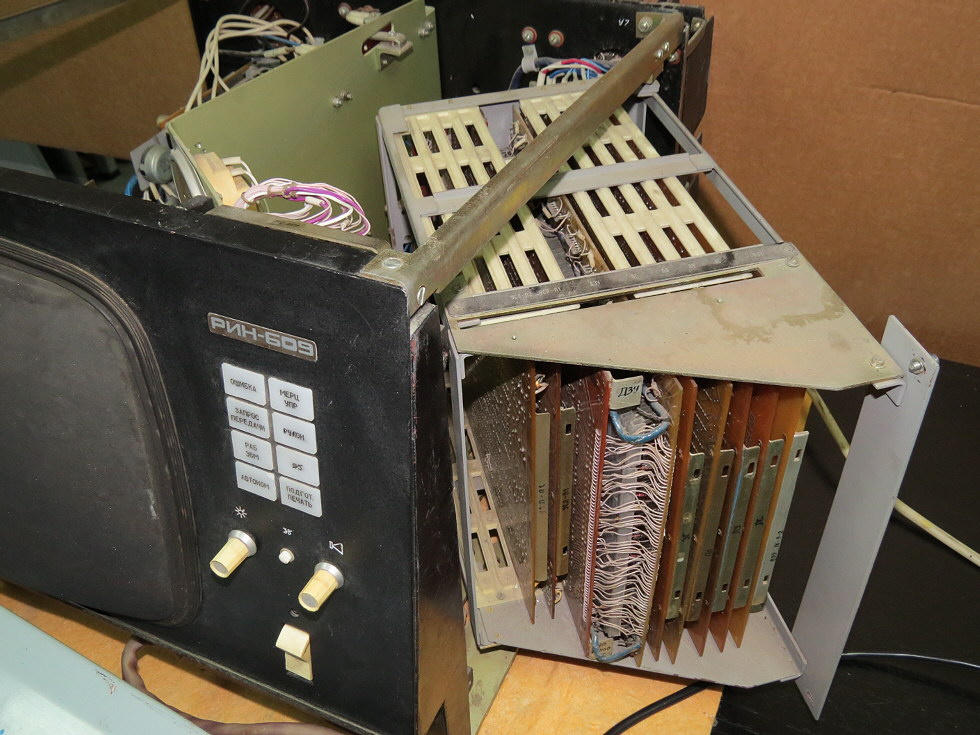
Logic boards on a rolling base. If anything, you can conveniently pull them out.
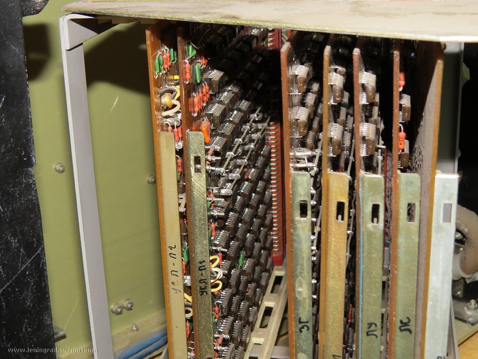
Each board is a complete module: COND - computer connection, SG - character generator (the one that draws vectors), LU - logic control, LAN - logical connections, RAM for storing on-screen symbols and DZU with character vector codes. Small logic chips.
The RAM in the first releases was on the magnetic cores. How it looked, you can see on that site: www.155la3.ru/ferrite_memory.htm . In 1982, it was replaced by K134RU6 semiconductor chips.
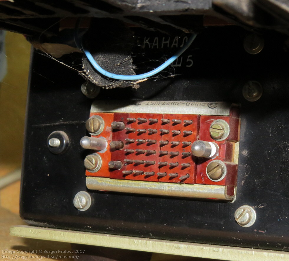
Communication connector with a computer type "set". Connectors of this type are recruited from several sub-connectors at the request of the customer, which, in principle, should be convenient, but they somehow did not take root. The interface to the computer is parallel.
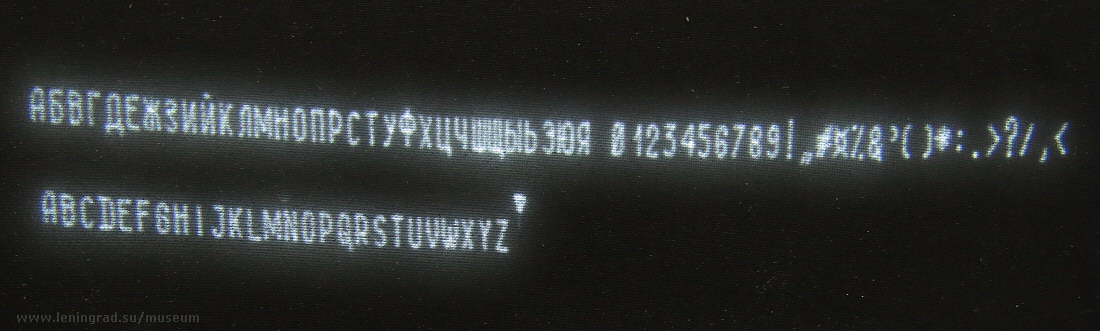
And this is the character generator of the monitor. In front of the monitor screen is a metal grid. It is designed to significantly improve the contrast of the image and suppress glare. She copes with this, only taking pictures of the characters themselves is not very close. This is how the characters look on the monitor screen.
The display itself displays 80 characters and 12 lines, which is significantly less than the traditional 80 characters for those times and 25 lines.
Judging by the documentation, the display was designed as a direct replacement for the popular Hungarian Videoton-340 display in M-400 or BESM-6 computers.
Videoton-340, one might say, the famous monitor (which, unfortunately, has not yet been obtained, and if anyone has one, let them know). This is the same monitor that stands on the table near Kalugina in the movie Office Romance.
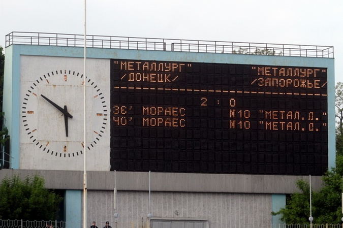
When buying any exhibit, if possible, I ask where this or that device was operated. Most often, such items are stored in a warehouse and information cannot be obtained, but in this case it was possible to learn its history. It turned out that he stood in the stadium and ran his information board. Then the display was replaced by Videoton-340, and he was sent to the warehouse, where he lay for a long time.
I have long wanted to know how and what controlled the scoreboard at the stadium. Now the puzzle is partially solved. That is, it turns out that the operator typed in the offline mode the information he wanted to output, pressed the transfer button, and the receiving equipment received the frame, stored it in the internal RAM, and was only engaged in scanning the scoreboard lamps. By and large, do not need any computer to display information - only the display and storage unit and scan on the scoreboard.
Since there were no programs, only an offline display mode and operator freedom of action, this explains that, in principle, there was no standard for displaying information on the scoreboard, and the current situation of the match was displayed arbitrarily. Here are a couple of photos of the scoreboard at various stadiums.

I typed an approximate text as it would appear on the display screen.

I do not remember who scored goals in that match, so the names of the players are shown conditionally.

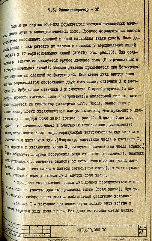
As in the raster type monitors, in the vector display, the symbols are located in familiarity - cells divided into 9 horizontal and 17 vertical lines, and for most signs, a coarser division into 9 vertical and 5 horizontal lines is used. There are two counters - X and Y.
But the most interesting is how the display output and how the movements of the vectors were encoded. Fortunately, a set of documentation was preserved, without which it would probably have been impossible to sort it out.
The character display is handled by the character generator board in conjunction with the DZU (long-term memory) card. DZU stores “programs” of vector output.
The display uses KOI7 encoding, it is 128 characters in the Russian and English keyboard layout and in capital letters (not lowercase), in numbers and special characters.
First, a byte (eight bits) of the first 128 cells is read, corresponding to the character code. This byte contains the address of the beginning of the program output symbol. Further, from the DZU, the program output codes of the character are read byte by bye until the zero byte (end of output) is encountered.
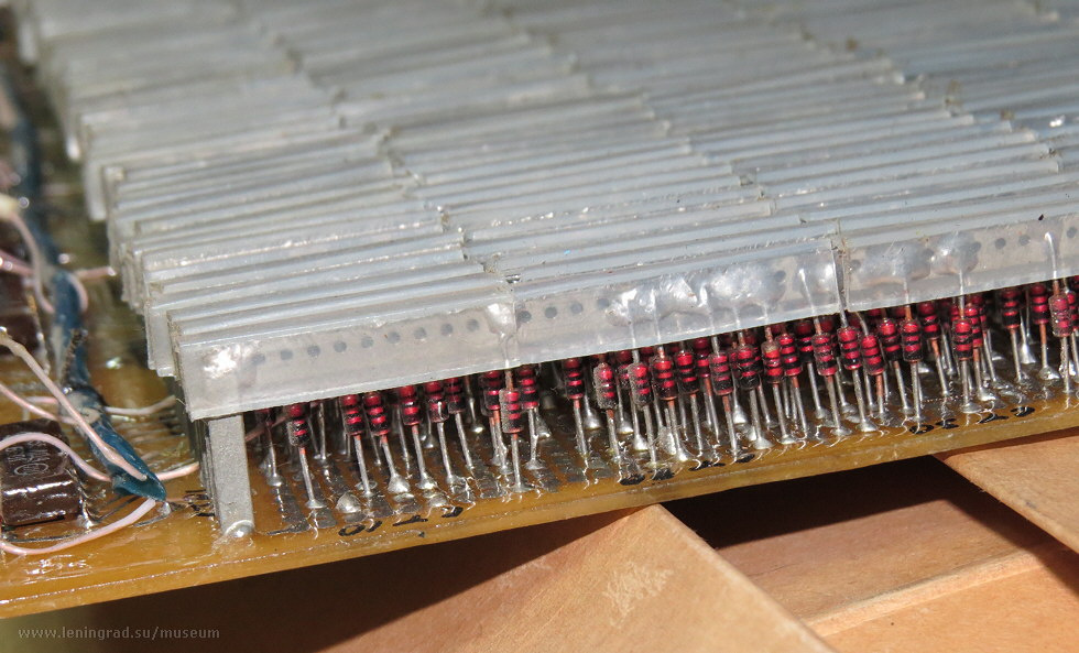
In total, DZU uses 912 eight-bit cells. And these cells are made in the form of a diode array.
In the diode matrix, unlike ROM chips, the diodes are installed only where the unit should be read. All other digits are "drawn" to zero. In total in the character generator costs 2003 diode (!). Here is this board:

I wonder what year we got the first ROM chips? And it is also interesting, why in the process of release the diode matrix was not subsequently changed to ROM chips? Changed in this display the RAM for storing the output information from the ferrite memory to integrated circuits. And then they did not change. Maybe these diodes were produced in the same factory, and their cost, including installation, was lower than the design and installation of ROM chips.
The economy, despite its planned character and inertia, was still at a high level, and all these costs were well calculated. Rational proposals may, who made, but probably the economic effect of its implementation was not so obvious for the alteration of the production technology of a serial product. Who knows.
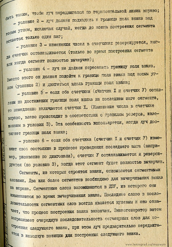
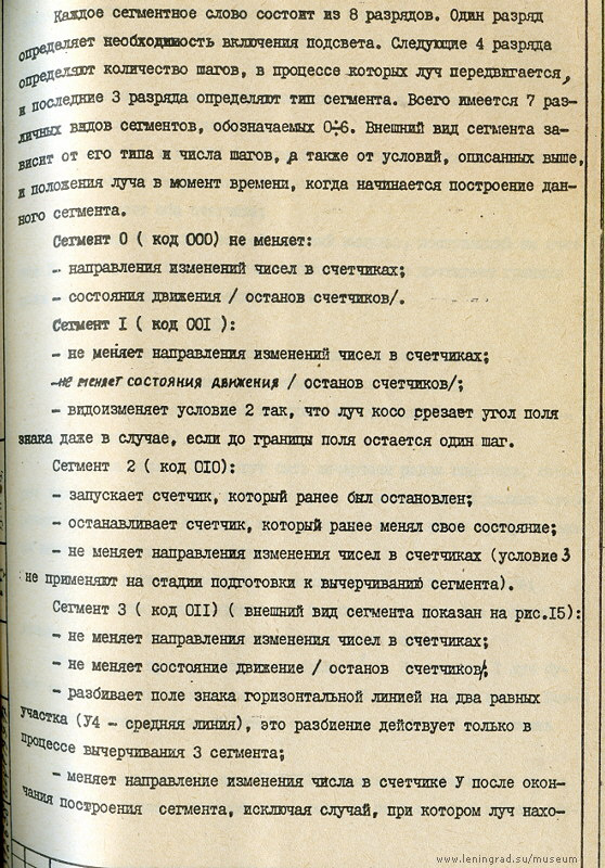
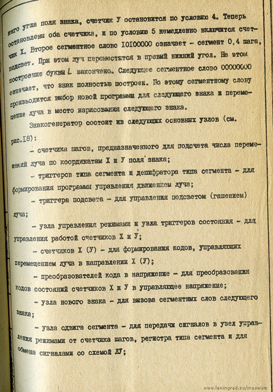
Each byte of the character-drawing program contains three fields: a single-bit field for turning on or not turning on the backlight (used for pre-setting the beam), a three-bit segment number (from 0 to 6) and a four-bit step counter. Segments is a built-in procedure (subroutine) for drawing a sub-element.
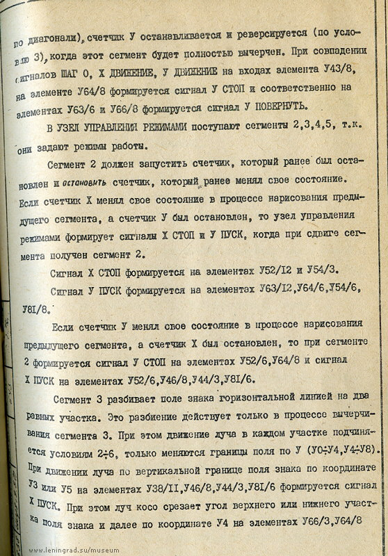
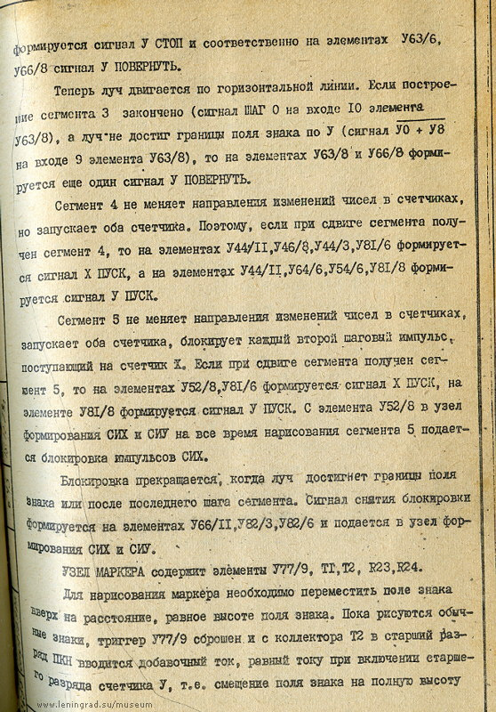
And besides the segments and the number of steps in the display are the so-called "conditions". This is a feature of the hardware drawing, which automatically (chip logic) do something with the beam. For example, in condition 2, the beam must approach the boundary of the sign field at an oblique angle, except for the case when one step remains until the end of the segment construction. That is, when one step remains to the edge of the mark field, and the beam moves perpendicular to it (for example, horizontally), then the automation will round it up and direct it up or down. When the beam reaches the upper edge, it will once again round and direct sideways. So you can draw a circle from the letter “P” simply by starting from the middle vertically and directing the beam to the right by 13 steps.
The links below are scanned images from the documentation that I didn’t open for unloading the page. Both the conditions and all types of segments used are described in great detail.
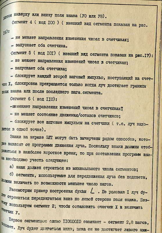


As a result, when using a combination of conditions and segments, seven bytes are used to draw the letter “I” (including the zero byte of the sign of the end of the output).
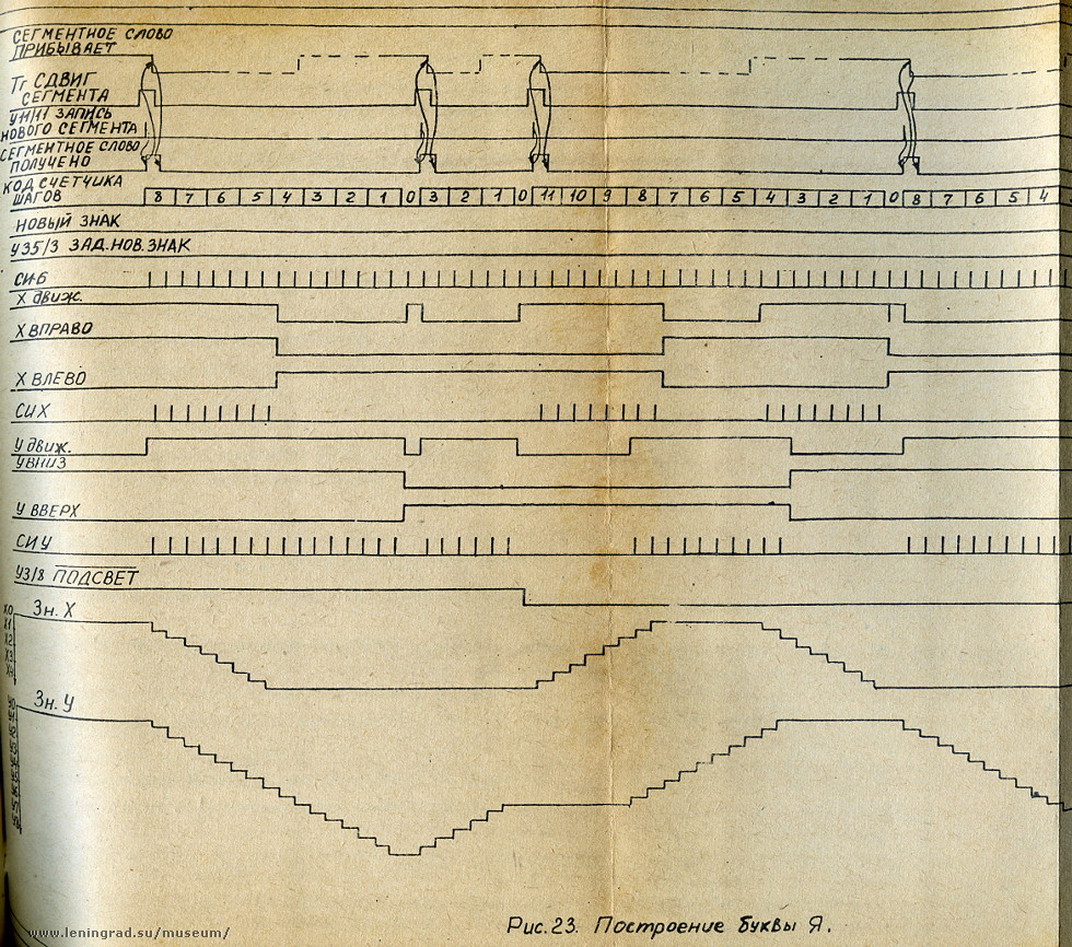
This scheme of constructing the letter "I" is already in the form of signals.
In general, very lucky that there is documentation, and not only the instruction manual, but also a technical description.
And it’s even good that this documentation is shown with all the corrections, because the paths the developers have taken are not always visible, having made this or that decision. We see only the end result, and the entire creative process is usually hidden from the end user.
Here, for example, what searches went on such an important node as the key blocking the keyboard:

Here, in fact, in brief, I talked about this monitor. I myself did not expect that the process of constructing symbols would turn out to be so convoluted. But this is part of the story, and thanks to the preserved monitor and, most importantly, its documentation, you can find out how this or that device worked.
Thanks for attention.
All Articles